2001 DODGE RAM catalytic converter
[x] Cancel search: catalytic converterPage 15 of 2889

It is even more important to look for gasoline with-
out MMT in Canada because MMT can be used at
levels higher than allowed in the United States.
MMT is prohibited in Federal and California refor-
mulated gasoline.
SULFUR IN GASOLINE
If you live in the northeast United States, your
vehicle may have been designed to meet California
low emission standards with Cleaner-Burning Cali-
fornia reformulated gasoline with low sulfur. If such
fuels are not available in states adopting California
emission standards, your vehicles will operate satis-
factorily on fuels meeting federal specifications, but
emission control system performance may be
adversely affected. Gasoline sold outside of California
is permitted to have higher sulfur levels which may
affect the performance of the vehicle's catalytic con-
verter. This may cause the Malfunction Indicator
Lamp (MIL), Check Engine or Service Engine Soon
light to illuminate. We recommend that you try a dif-
ferent brand of unleaded gasoline having lower sulfur
to determine if the problem is fuel related prior to
returning your vehicle to an authorized dealer for
service.
CAUTION: If the Malfunction Indicator Lamp (MIL),
Check Engine or Service Engine Soon light is flash-
ing, immediate service is required; see on-board
diagnostics system section.
MATERIALS ADDED TO FUEL
All gasoline sold in the United States and Canada
are required to contain effective detergent additives.
Use of additional detergents or other additives is not
needed under normal conditions.
FUEL SYSTEM CAUTIONS
CAUTION: Follow these guidelines to maintain your
vehicle's performance:
²The use of leaded gas is prohibited by Federal
law. Using leaded gasoline can impair engine perfor-
mance, damage the emission control system, and
could result in loss of warranty coverage.
²An out-of-tune engine, or certain fuel or ignition
malfunctions, can cause the catalytic converter to
overheat. If you notice a pungent burning odor or
some light smoke, your engine may be out of tune or
malfunctioning and may require immediate service.
Contact your dealer for service assistance.²When pulling a heavy load or driving a fully
loaded vehicle when the humidity is low and the tem-
perature is high, use a premium unleaded fuel to
help prevent spark knock. If spark knock persists,
lighten the load, or engine piston damage may result.
²The use of fuel additives which are now being
sold as octane enhancers is not recommended. Most
of these products contain high concentrations of
methanol. Fuel system damage or vehicle perfor-
mance problems resulting from the use of such fuels
or additives is not the responsibility of Daimler-
Chrysler Corporation and may not be covered under
the new vehicle warranty.
NOTE: Intentional tampering with emissions control
systems can result in civil penalties being assessed
against you.
DESCRIPTION - FUEL REQUIREMENTS -
DIESEL ENGINE
DESCRIPTION
WARNING: Do not use alcohol or gasoline as a fuel
blending agent. They can be unstable under certain
conditions and hazardous or explosive when mixed
with diesel fuel.
Use good quality diesel fuel from a reputable sup-
plier in your Dodge truck. For most year-round ser-
vice, number 2 diesel fuel meeting ASTM
specification D-975 will provide good performance. If
the vehicle is exposed to extreme cold (below 0ÉF/-
18ÉC), or is required to operate at colder-than-normal
conditions for prolonged periods, use climatized No. 2
diesel fuel or dilute the No. 2 diesel fuel with 50%
No. 1 diesel fuel. This will provide better protection
from fuel gelling or wax-plugging of the fuel filters.
Diesel fuel is seldom completely free of water. To
prevent fuel system trouble, including fuel line freez-
ing in winter, drain the accumulated water from the
fuel/water separator using the fuel/water separator
drain provided. If you buy good-quality fuel and fol-
low the cold-weather advice above, fuel conditioners
should not be required in your vehicle. If available in
your area, a high cetane ªpremiumº diesel fuel may
offer improved cold starting and warm-up perfor-
mance.
0 - 2 LUBRICATION & MAINTENANCEBR/BE
LUBRICATION & MAINTENANCE (Continued)
Page 341 of 2889
hoses, gasket edges and heater. Seal small leak holes
with a Sealer Lubricant (or equivalent). Repair leak
holes and inspect system again with pressure
applied.
Drops Quickly:Indicates that serious leakage is
occurring. Examine system for external leakage. If
leaks are not visible, inspect for internal leakage.
Large radiator leak holes should be repaired by a
reputable radiator repair shop.
INTERNAL LEAKAGE INSPECTION
Remove engine oil pan drain plug and drain a
small amount of engine oil. If coolant is present in
the pan, it will drain first because it is heavier than
oil. An alternative method is to operate engine for a
short period to churn the oil. After this is done,
remove engine dipstick and inspect for water glob-
ules. Also inspect transmission dipstick for water
globules and transmission fluid cooler for leakage.
WARNING: WITH RADIATOR PRESSURE TESTER
TOOL INSTALLED ON RADIATOR, DO NOT ALLOW
PRESSURE TO EXCEED 110 KPA (20 PSI). PRES-
SURE WILL BUILD UP QUICKLY IF A COMBUSTION
LEAK IS PRESENT. TO RELEASE PRESSURE,
ROCK TESTER FROM SIDE TO SIDE. WHEN
REMOVING TESTER, DO NOT TURN TESTER MORE
THAN 1/2 TURN IF SYSTEM IS UNDER PRESSURE.
Operate engine without pressure cap on radiator
until thermostat opens. Attach a Pressure Tester to
filler neck. If pressure builds up quickly it indicates a
combustion leak exists. This is usually the result of a
cylinder head gasket leak or crack in engine. Repair
as necessary.
If there is not an immediate pressure increase,
pump the Pressure Tester. Do this until indicated
pressure is within system range of 110 kPa (16 psi).
Fluctuation of gauge pointer indicates compression or
combustion leakage into cooling system.
Because the vehicle is equipped with a catalytic
converter,do notremove spark plug cables or short
out cylinders to isolate compression leak.If the needle on dial of pressure tester does not
fluctuate, race engine a few times to check for an
abnormal amount of coolant or steam. This would be
emitting from exhaust pipe. Coolant or steam from
exhaust pipe may indicate a faulty cylinder head gas-
ket, cracked engine cylinder block or cylinder head.
A convenient check for exhaust gas leakage into
cooling system is provided by a commercially avail-
able Block Leak Check tool. Follow manufacturers
instructions when using this product.COMBUSTION LEAKAGE TESTÐWITHOUT
PRESSURE TESTER
DO NOT WASTE reusable coolant. If solution is
clean, drain coolant into a clean container for reuse.
WARNING: DO NOT REMOVE CYLINDER BLOCK
DRAIN PLUGS OR LOOSEN RADIATOR DRAIN-
COCK WITH SYSTEM HOT AND UNDER PRESSURE.
SERIOUS BURNS FROM COOLANT CAN OCCUR.
Drain sufficient coolant to allow thermostat
removal. (Refer to 7 - COOLING/ENGINE/ENGINE
COOLANT THERMOSTAT - REMOVAL). Remove
accessory drive belt (Refer to 7 - COOLING/ACCES-
SORY DRIVE/DRIVE BELTS - REMOVAL).
Add coolant to radiator to bring level to within 6.3
mm (1/4 in) of top of thermostat housing.
CAUTION: Avoid overheating. Do not operate
engine for an excessive period of time. Open drain-
cock immediately after test to eliminate boil over.
Start engine and accelerate rapidly three times, to
approximately 3000 rpm while observing coolant. If
internal engine combustion gases are leaking into
cooling system, bubbles will appear in coolant. If bub-
bles do not appear, internal combustion gas leakage
is not present.
7 - 6 COOLINGBR/BE
COOLING (Continued)
Page 556 of 2889
CLEANING
The plugs may be cleaned using commercially
available spark plug cleaning equipment. After clean-
ing, file center electrode flat with a small point file or
jewelers file before adjusting gap.
CAUTION: Never use a motorized wire wheel brush
to clean spark plugs. Metallic deposits will remain
on spark plug insulator and will cause plug misfire.
INSTALLATION
Special care should be taken when installing spark
plugs into the cylinder head spark plug wells. Be
sure the plugs do not drop into the plug wells as elec-
trodes can be damaged.
Always tighten spark plugs to the specified torque.
Over tightening can cause distortion resulting in a
change in the spark plug gap or a cracked porcelain
insulator.
When replacing the spark plug and ignition coil
cables, route the cables correctly and secure them in
the appropriate retainers. Failure to route the cables
properly can cause the radio to reproduce ignition
noise. It could cause cross ignition of the spark plugs
or short circuit the cables to ground.
(1) Start the spark plug into the cylinder head by
hand to avoid cross threading.
(2) Tighten spark plugs to 35-41 N´m (26-30 ft.
lbs.) torque.
(3) Install spark plug cables over spark plugs.
SPARK PLUG CABLE
DESCRIPTION
Spark plug cables are sometimes referred to as sec-
ondary ignition wires.
OPERATION
The spark plug cables transfer electrical current
from the ignition coil(s) and/or distributor, to individ-
ual spark plugs at each cylinder. The resistive spark
plug cables are of nonmetallic construction. The
cables provide suppression of radio frequency emis-
sions from the ignition system.
DIAGNOSIS AND TESTING - SPARK PLUG
CABLES
Cable routing is important on certain engines. To
prevent possible ignition crossfire, be sure the cables
are clipped into the plastic routing looms. Try to pre-
vent any one cable from contacting another. Before
removing cables, note their original location and
routing. Never allow one cable to be twisted around
another.
Check the spark plug cable connections for good
contact at the coil(s), distributor cap towers, and
spark plugs. Terminals should be fully seated. The
insulators should be in good condition and should fit
tightly on the coil, distributor and spark plugs. Spark
plug cables with insulators that are cracked or torn
must be replaced.
Clean high voltage ignition cables with a cloth
moistened with a non-flammable solvent. Wipe the
cables dry. Check for brittle or cracked insulation.
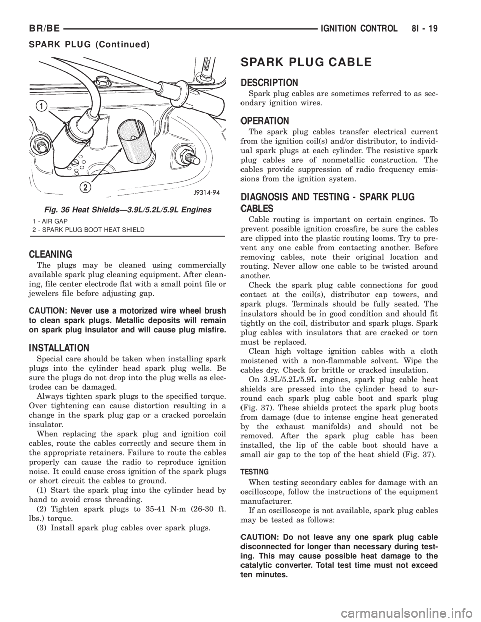
On 3.9L/5.2L/5.9L engines, spark plug cable heat
shields are pressed into the cylinder head to sur-
round each spark plug cable boot and spark plug
(Fig. 37). These shields protect the spark plug boots
from damage (due to intense engine heat generated
by the exhaust manifolds) and should not be
removed. After the spark plug cable has been
installed, the lip of the cable boot should have a
small air gap to the top of the heat shield (Fig. 37).
TESTING
When testing secondary cables for damage with an
oscilloscope, follow the instructions of the equipment
manufacturer.
If an oscilloscope is not available, spark plug cables
may be tested as follows:
CAUTION: Do not leave any one spark plug cable
disconnected for longer than necessary during test-
ing. This may cause possible heat damage to the
catalytic converter. Total test time must not exceed
ten minutes.
Fig. 36 Heat ShieldsÐ3.9L/5.2L/5.9L Engines
1 - AIR GAP
2 - SPARK PLUG BOOT HEAT SHIELD
BR/BEIGNITION CONTROL 8I - 19
SPARK PLUG (Continued)
Page 1097 of 2889
Connector Name/Number Color Location Fig.
Oxygen Sensor 1/1 Left Bank Up Left Exhaust Manifold Downpipe 13
Oxygen Sensor 1/1 Upstream Catalytic Converter Inlet Side 13
Oxygen Sensor 1/2 Downstream Catalytic Converter Outlet Side 13
Oxygen Sensor 1/2 Left Bank Down Catalytic Converter Outlet Side 13
Oxygen Sensor 1/2 Pre-catalyst Catalytic Converter Inlet Side 13
Oxygen Sensor 1/3 Post Catalyst Catalytic Converter Outlet Side 13
Oxygen Sensor 1/3 Post Catalyst Post Catalyst 13
Oxygen Sensor 2/1 Right Bank Up Right Exhaust Manifold Downpipe 13
Oxygen Sensor 2/2 Right Bank Down Catalytic Converter Outlet Side 13
Park/Neutral Position Switch BK Left Side of Transmission 13
Passenger Airbag At Glove Box 23,26
Passenger Airbag On/Off Switch C1 Lower Right Side of Instrument
Panel23
Passenger Airbag On/Off Switch C2 Lower Right Side of Instrument
Panel23
Passenger Door Arm/Disarm Switch LTGY In Door 19
Passenger Door Jamb Switch NAT In Door 19
Passenger Door Lock Motor BK In Door 19
Passenger Door Window/Lock Switch In Door 19
Passenger Heated Seat Switch BL Center of Instrument Panel N/S
Passenger Heated Seat Module Under Seat N/S
Passenger Lumbar Motor Under Seat N/S
Passenger Power Seat Front Vertical Motor Under Seat N/S
Passenger Power Seat Horizontal Motor Under Seat N/S
Passenger Power Seat Rear Vertical Motor Under Seat N/S
Passenger Power Seat Switch At Seat N/S
Passenger Power Window Motor In Door N/S
Power Seat Heater Control Module Under Seat N/S
Power Mirror Switch Driver Door 19
Power Outlet BK Center of I.P. 25
Powertrain Control Module C1 Right Rear Engine Compartment 1,2
Powertrain Control Module C2 Right Rear Engine Compartment 1,2
Powertrain Control Module C3 Right Rear Engine Compartment 1,2
Radio Choke Relay BK Instrument Panel Center support 23,25
Radio C1 GY Rear of Radio 25
Radio C2 BK Rear of Radio 25
Radio C3 BK Instrument Panel Center support 25
Rear Wheel Speed Sensor BK Left Frame Rail, Near Fuel Tank 21,22
Right Back-Up Lamp BK Rear of Lamp N/S
Right Fog Lamp BK Rear of Fog Lamp N/S
Right Front Door Speaker(Premium BK In Door 19
Right Front Door Speaker(Standard BK In Door 19
Right Front Fender Lamp On Fender 21
8W - 90 - 6 8W-90 CONNECTOR/GROUND LOCATIONSBR/BE
CONNECTOR/GROUND LOCATIONS (Continued)
Page 1456 of 2889
EXHAUST SYSTEM
TABLE OF CONTENTS
page page
EXHAUST SYSTEM
DESCRIPTION............................1
DIAGNOSIS AND TESTING..................4
GAS ENGINE...........................4
DIESEL ENGINE........................4
SPECIFICATIONS.........................5
CATALYTIC CONVERTER - 3.9L/5.2L/5.9L
DESCRIPTION............................5
OPERATION.............................5
REMOVAL...............................5
INSPECTION.............................5
INSTALLATION............................5
CATALYTIC CONVERTER - 5.9L HEAVY
DUTY/8.0L
DESCRIPTION............................6
OPERATION.............................6
REMOVAL...............................6
INSPECTION.............................7
INSTALLATION............................7
EXHAUST PIPE - 3.9L/5.2L/5.9L
REMOVAL...............................7
INSPECTION.............................7
INSTALLATION............................7
EXHAUST PIPE - 5.9L HEAVY DUTY/8.0L
REMOVAL...............................8
INSPECTION.............................9
INSTALLATION............................9
EXHAUST PIPE - 5.9L DIESEL
REMOVAL...............................9
INSPECTION.............................9
INSTALLATION...........................10
HEAT SHIELDS
DESCRIPTION...........................10
REMOVAL..............................10
INSTALLATION...........................10MUFFLER - 3.9L/5.2L/5.9L/8.0L
REMOVAL..............................10
INSTALLATION...........................11
MUFFLER - 5.9L DIESEL
REMOVAL..............................11
INSTALLATION...........................11
TAILPIPE - 3.9L/5.2L/5.9L
REMOVAL..............................11
INSPECTION............................11
INSTALLATION...........................12
TAILPIPE - 5.9L HEAVY DUTY/8.0L
REMOVAL..............................12
INSPECTION............................12
INSTALLATION...........................12
TAILPIPE - 5.9L DIESEL
REMOVAL..............................12
INSPECTION............................12
INSTALLATION...........................12
RESONATOR
REMOVAL..............................13
INSTALLATION...........................13
TURBOCHARGER
DESCRIPTION...........................13
OPERATION.............................13
REMOVAL..............................15
CLEANING..............................16
INSPECTION............................16
INSTALLATION...........................16
CHARGE AIR COOLER AND PLUMBING
DESCRIPTION...........................17
OPERATION.............................17
REMOVAL..............................17
CLEANING..............................18
INSPECTION............................18
INSTALLATION...........................18
EXHAUST SYSTEM
DESCRIPTIONÐ3.9L/5.2L/5.9/8.0L
CAUTION: Avoid application of rust prevention com-
pounds or undercoating materials to exhaust sys-tem floor pan exhaust heat shields. Light overspray
near the edges is permitted. Application of coating
will result in excessive floor pan temperatures and
objectionable fumes.
BR/BEEXHAUST SYSTEM 11 - 1
Page 1457 of 2889
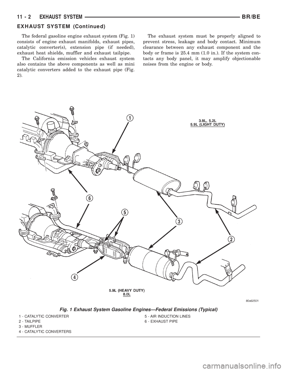
The federal gasoline engine exhaust system (Fig. 1)
consists of engine exhaust manifolds, exhaust pipes,
catalytic converter(s), extension pipe (if needed),
exhaust heat shields, muffler and exhaust tailpipe.
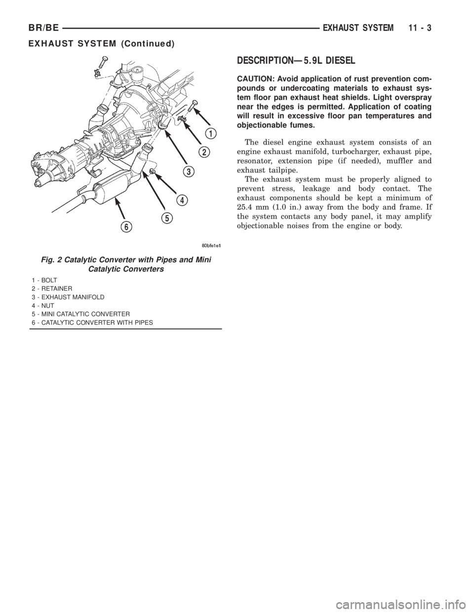
The California emission vehicles exhaust system
also contains the above components as well as mini
catalytic converters added to the exhaust pipe (Fig.
2).The exhaust system must be properly aligned to
prevent stress, leakage and body contact. Minimum
clearance between any exhaust component and the
body or frame is 25.4 mm (1.0 in.). If the system con-
tacts any body panel, it may amplify objectionable
noises from the engine or body.
Fig. 1 Exhaust System Gasoline EnginesÐFederal Emissions (Typical)
1 - CATALYTIC CONVERTER
2 - TAILPIPE
3 - MUFFLER
4 - CATALYTIC CONVERTERS5 - AIR INDUCTION LINES
6 - EXHAUST PIPE
11 - 2 EXHAUST SYSTEMBR/BE
EXHAUST SYSTEM (Continued)
Page 1458 of 2889
DESCRIPTIONÐ5.9L DIESEL
CAUTION: Avoid application of rust prevention com-
pounds or undercoating materials to exhaust sys-
tem floor pan exhaust heat shields. Light overspray
near the edges is permitted. Application of coating
will result in excessive floor pan temperatures and
objectionable fumes.
The diesel engine exhaust system consists of an
engine exhaust manifold, turbocharger, exhaust pipe,
resonator, extension pipe (if needed), muffler and
exhaust tailpipe.
The exhaust system must be properly aligned to
prevent stress, leakage and body contact. The
exhaust components should be kept a minimum of
25.4 mm (1.0 in.) away from the body and frame. If
the system contacts any body panel, it may amplify
objectionable noises from the engine or body.
Fig. 2 Catalytic Converter with Pipes and Mini
Catalytic Converters
1 - BOLT
2 - RETAINER
3 - EXHAUST MANIFOLD
4 - NUT
5 - MINI CATALYTIC CONVERTER
6 - CATALYTIC CONVERTER WITH PIPES
BR/BEEXHAUST SYSTEM 11 - 3
EXHAUST SYSTEM (Continued)
Page 1459 of 2889

DIAGNOSIS AND TESTING - GAS ENGINE
EXHAUST SYSTEM DIAGNOSIS CHART
CONDITION POSSIBLE CAUSE CORRECTION
EXCESSIVE EXHAUST NOISE OR
LEAKING EXHAUST GASES1. Leaks at pipe joints. 1. Tighten clamps/bolts at leaking
joints.
2. Rusted or blown out muffler. 2. Replace muffler. Inspect exhaust
system.
3. Broken or rusted out exhaust
pipe.3. Replace exhaust pipe.
4. Exhaust pipe leaking at manifold
flange.4. Tighten/replace flange attaching
nuts/bolts.
5. Exhaust manifold cracked or
broken.5. Replace exhaust manifold.
6. Leak between exhaust manifold
and cylinder head.6. Tighten exhaust manifold to
cylinder head bolts.
7. Catalytic converter rusted or
blown out.7. Replace catalytic converter assy.
8. Restriction in exhaust system. 8. Remove restriction, if possible.
Replace restricted part if necessary.
caution:
When servicing and replacing exhaust system components, disconnect the oxygen sensor connector(s).
Allowing the exhaust to hang by the oxygen sensor wires will damage the harness and/or sensor.
DIAGNOSIS AND TESTING - DIESEL ENGINE
EXHAUST SYSTEM DIAGNOSIS CHART
CONDITION POSSIBLE CAUSE CORRECTION
EXCESSIVE EXHAUST NOISE OR
LEAKING EXHAUST GASES1. Leaks at pipe joints. 1. Tighten clamps/bolts at leaking
joints.
2. Rusted or blown out muffler. 2. Replace muffler. Inspect exhaust
system.
3. Broken or rusted out exhaust
pipe.3. Replace exhaust pipe.
4. Exhaust pipe leaking at manifold
flange.4. Tighten/replace flange attaching
nuts/bolts.
5. Exhaust manifold cracked or
broken.5. Replace exhaust manifold.
6. Leak between exhaust manifold
and cylinder head.6. Tighten exhaust manifold to
cylinder head bolts.
7. Turbocharger mounting flange
cracked.7. Remove turbocharger and
inspect. (Refer to 11 - EXHAUST
SYSTEM/TURBOCHARGER
SYSTEM/TURBOCHARGER -
REMOVAL).
8. Restriction in exhaust system. 8. Remove restriction, if possible.
Replace restricted part if necessary.
11 - 4 EXHAUST SYSTEMBR/BE
EXHAUST SYSTEM (Continued)