2001 DODGE RAM instrument cluster
[x] Cancel search: instrument clusterPage 1 of 2889

GROUP TAB LOCATOR
Introduction
0Lubrication & Maintenance
2Suspension
3Differential & Driveline
5Brakes
7Cooling
8AAudio
8BChime/Buzzer
8EElectronic Control Modules
8FEngine Systems
8GHeated Systems
8HHorn
8IIgnition Control
8JInstrument Cluster
8LLamps
8MMessage Systems
8NPower Systems
8ORestraints
8PSpeed Control
8QVehicle Theft Security
8RWipers/Washers
8WWiring
9Engine
11Exhaust System
13Frame & Bumpers
14Fuel System
19Steering
21Transmission/Transaxle
22Tires/Wheels
23Body
24Heating & Air Conditioning
25Emissions Control Systems
30New Vehicle Preparation
Component and System Index
Service Manual Comment Forms (Rear of Manual)
Page 342 of 2889

DIAGNOSIS AND TESTING - COOLING SYSTEM
GAS ENGINE
COOLING SYSTEM DIAGNOSISÐGASOLINE ENGINE
CONDITION POSSIBLE CAUSES CORRECTION
TEMPERATURE
GAUGE READS LOW1. Has a Diagnostic Trouble Code (DTC)
been set indicating a stuck open
thermostat?1. (Refer to 25 - EMISSIONS CONTROL -
DESCRIPTION) for On-Board Diagnostics
and DTC information. Replace thermostat
if necessary.
2. Is the temperature sending unit
connected?2. Check the temperature sensor
connector. (Refer to 8 - ELECTRICAL/
INSTRUMENT CLUSTER - SCHEMATIC -
ELECTRICAL) Repair connector if
necessary.
3. Is the temperature gauge operating
OK?3. Check gauge operation. (Refer to 8 -
ELECTRICAL/INSTRUMENT CLUSTER/
ENGINE TEMPERATURE GAUGE -
DESCRIPTION) . Repair as necessary.
4. Coolant level low in cold ambient
temperatures accompanied with poor
heater performance.4. Check coolant level in the coolant
reserve/overflow tank and the radiator.
Inspect system for leaks. Repair leaks as
necessary. Refer to the Coolant section of
the manual text for WARNINGS and
CAUTIONS associated with removing the
radiator cap.
5. Improper operation of internal heater
doors or heater controls.5. Inspect heater and repair as necessary.
(Refer to 24 - HEATING & AIR
CONDITIONING - DIAGNOSIS AND
TESTING) for procedures.
TEMPERATURE
GAUGE READS HIGH
OR THE COOLANT
WARNING LAMP
ILLUMINATES.
COOLANT MAY OR
MAY NOT BE LOST OR
LEAKING FROM THE
COOLING SYSTEM1. Trailer is being towed, a steep hill is
being climbed, vehicle is operated in slow
moving traffic, or engine is being idled
with very high ambient (outside)
temperatures and the air conditioning is
on. Higher altitudes could aggravate
these conditions.1. This may be a temporary condition and
repair is not necessary. Turn off the air
conditioning and attempt to drive the
vehicle without any of the previous
conditions. Observe the temperature
gauge. The gauge should return to the
normal range. If the gauge does not
return to the normal range, determine the
cause for overheating and repair. Refer to
Possible Causes (2-20).
2. Is the temperature gauge reading
correctly?2. Check gauge. (Refer to 8 -
ELECTRICAL/INSTRUMENT CLUSTER -
SCHEMATIC - ELECTRICAL) . Repair as
necessary.
3. Is the temperature warning illuminating
unnecessarily?3. (Refer to 8 - ELECTRICAL/
INSTRUMENT CLUSTER - SCHEMATIC -
ELECTRICAL).
4. Coolant low in coolant reserve/overflow
tank and radiator?4. Check for coolant leaks and repair as
necessary. (Refer to 7 - COOLING -
DIAGNOSIS AND TESTING).
BR/BECOOLING 7 - 7
COOLING (Continued)
Page 344 of 2889

CONDITION POSSIBLE CAUSES CORRECTION
16. Thermostat partially or completely
shut.16. Check thermostat operation and
replace as necessary. (Refer to 7 -
COOLING/ENGINE/ENGINE COOLANT
THERMOSTAT - REMOVAL) .
17. Viscous fan drive not operating
properly.17. Check fan drive operation and replace
as necessary. (Refer to 7 - COOLING/
ENGINE/FAN DRIVE VISCOUS CLUTCH
- REMOVAL) .
18. Cylinder head gasket leaking. 18. Check for cylinder head gasket leaks.
(Refer to 7 - COOLING - DIAGNOSIS
AND TESTING).
19. Heater core leaking. 19. Check heater core for leaks. (Refer to
24 - HEATING & AIR CONDITIONING/
PLUMBING - DIAGNOSIS AND
TESTING). Repair as necessary.
TEMPERATURE
GAUGE READING IS
INCONSISTENT
(FLUCTUATES,
CYCLES OR IS
ERRATIC)1. During cold weather operation, with the
heater blower in the high position, the
gauge reading may drop slightly.1. A normal condition. No correction is
necessary.
2. Temperature gauge or engine mounted
gauge sensor defective or shorted. Also,
corroded or loose wiring in this circuit.2. Check operation of gauge and repair if
necessary. (Refer to 8 - ELECTRICAL/
INSTRUMENT CLUSTER - DIAGNOSIS
AND TESTING).
3. Gauge reading rises when vehicle is
brought to a stop after heavy use (engine
still running)3. A normal condition. No correction is
necessary. Gauge should return to normal
range after vehicle is driven.
4. Gauge reading high after re-starting a
warmed up (hot) engine.4. A normal condition. No correction is
necessary. The gauge should return to
normal range after a few minutes of
engine operation.
5. Coolant level low in radiator (air will
build up in the cooling system causing
the thermostat to open late).5. Check and correct coolant leaks. (Refer
to 7 - COOLING - DIAGNOSIS AND
TESTING).
6. Cylinder head gasket leaking allowing
exhaust gas to enter cooling system
causing a thermostat to open late.6. (a) Check for cylinder head gasket
leaks. (Refer to 7 - COOLING -
DIAGNOSIS AND TESTING).
(b) Check for coolant in the engine oil.
Inspect for white steam emitting from the
exhaust system. Repair as necessary.
7. Water pump impeller loose on shaft. 7. Check water pump and replace as
necessary. (Refer to 7 - COOLING/
ENGINE/WATER PUMP - REMOVAL).
8. Loose accessory drive belt. (water
pump slipping)8. (Refer to 7 - COOLING/ACCESSORY
DRIVE/DRIVE BELTS - DIAGNOSIS AND
TESTING). Check and correct as
necessary.
9. Air leak on the suction side of the
water pump allows air to build up in
cooling system causing thermostat to
open late.9. Locate leak and repair as necessary.
BR/BECOOLING 7 - 9
COOLING (Continued)
Page 347 of 2889

CONDITION POSSIBLE CAUSES CORRECTION
COOLANT COLOR 1. Coolant color is not necessarily an
indication of adequate corrosion or
temperature protection. Do not rely on
coolant color for determining condition of
coolant.1. (Refer to LUBRICATION &
MAINTENANCE/FLUID TYPES -
DESCRIPTION). Adjust coolant mixture
as necessary.
COOLANT LEVEL
CHANGES IN
COOLANT RESERVE/
OVERFLOW TANK.
TEMPERATURE
GAUGE IS IN NORMAL
RANGE1. Level changes are to be expected as
coolant volume fluctuates with engine
temperature. If the level in the tank was
between the FULL and ADD marks at
normal operating temperature, the level
should return to within that range after
operation at elevated temperatures.1. A normal condition. No repair is
necessary.
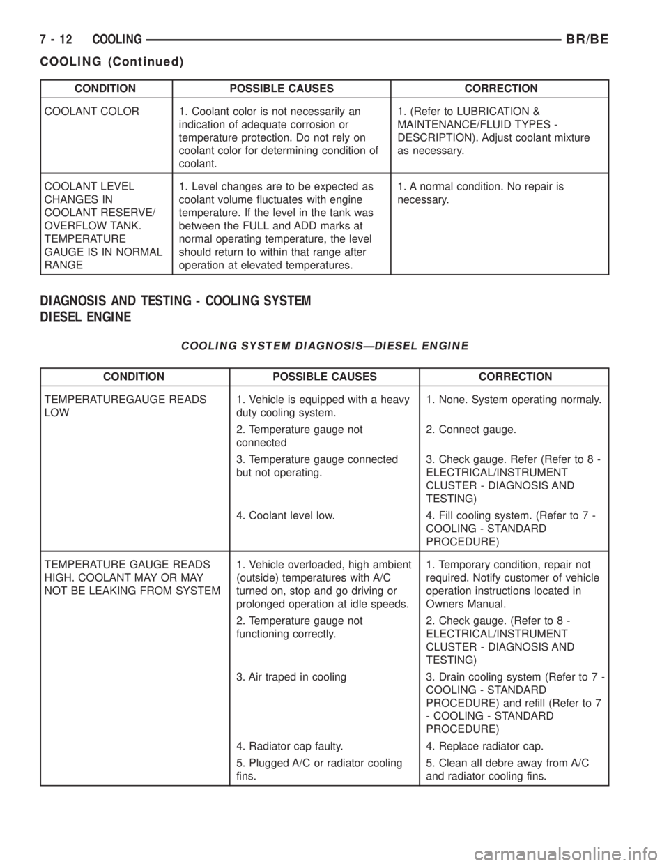
DIAGNOSIS AND TESTING - COOLING SYSTEM
DIESEL ENGINE
COOLING SYSTEM DIAGNOSISÐDIESEL ENGINE
CONDITION POSSIBLE CAUSES CORRECTION
TEMPERATUREGAUGE READS
LOW1. Vehicle is equipped with a heavy
duty cooling system.1. None. System operating normaly.
2. Temperature gauge not
connected2. Connect gauge.
3. Temperature gauge connected
but not operating.3. Check gauge. Refer (Refer to 8 -
ELECTRICAL/INSTRUMENT
CLUSTER - DIAGNOSIS AND
TESTING)
4. Coolant level low. 4. Fill cooling system. (Refer to 7 -
COOLING - STANDARD
PROCEDURE)
TEMPERATURE GAUGE READS
HIGH. COOLANT MAY OR MAY
NOT BE LEAKING FROM SYSTEM1. Vehicle overloaded, high ambient
(outside) temperatures with A/C
turned on, stop and go driving or
prolonged operation at idle speeds.1. Temporary condition, repair not
required. Notify customer of vehicle
operation instructions located in
Owners Manual.
2. Temperature gauge not
functioning correctly.2. Check gauge. (Refer to 8 -
ELECTRICAL/INSTRUMENT
CLUSTER - DIAGNOSIS AND
TESTING)
3. Air traped in cooling 3. Drain cooling system (Refer to 7 -
COOLING - STANDARD
PROCEDURE) and refill (Refer to 7
- COOLING - STANDARD
PROCEDURE)
4. Radiator cap faulty. 4. Replace radiator cap.
5. Plugged A/C or radiator cooling
fins.5. Clean all debre away from A/C
and radiator cooling fins.
7 - 12 COOLINGBR/BE
COOLING (Continued)
Page 348 of 2889

CONDITION POSSIBLE CAUSES CORRECTION
6. Coolant mixture incorrect. 6. Drain cooling system (Refer to 7 -
COOLING - STANDARD
PROCEDURE) refill with correct
mixture (Refer to 7 - COOLING -
STANDARD PROCEDURE).
7. Thermostat stuck shut. 7. Replace thermostat.
8. Bug screen or winter front being
used.8. Remove bug screen or winter
front.
9. Viscous fan drive not operating
properly.9. Check viscous fan (Refer to 7 -
COOLING/ENGINE/FAN DRIVE
VISCOUS CLUTCH - DIAGNOSIS
AND TESTING)
10. Cylinder head gasket leaking. 10. Check for leaking head gaskets
(Refer to 7 - COOLING -
DIAGNOSIS AND TESTING).
11. Heater core leaking. 11. Replace heater core.
12. cooling system hoses leaking. 12. Tighten clamps or Replace
hoses.
13. Brakes dragging. 13. Check brakes. (Refer to 5 -
BRAKES/HYDRAULIC/
MECHANICAL - DIAGNOSIS AND
TESTING)
TEMPERATURE GAUGE READING
INCONSISTENT ( ERRATIC,
CYCLES OR FLUCTUATES)1. Heavy duty cooling system,
extream cold ambient (outside)
temperature or heater blower motor
in high position.1. None. System operating normaly.
2. Temperature gauge or gauge
sensor defective.2. Check gauge. (Refer to 8 -
ELECTRICAL/INSTRUMENT
CLUSTER - DIAGNOSIS AND
TESTING)
3. Temporary heavy usage or load. 3. None. Normal condition.
4. Air traped in cooling system. 4. Fill cooling system (Refer to 7 -
COOLING - STANDARD
PROCEDURE).
5. Water pump 5. Replace water pump.
6. Air leak on suction side of water
pump.6. Check for leak. (Refer to 7 -
COOLING - DIAGNOSIS AND
TESTING)
RADIATOR CAP LEAKING STEAM
AND /OR COOLANT INTO
RESERVOIR BOTTLE.
(TEMPERATURE GAUGE MAY
READ HIGH)1. Radiator cap defective. 1. Replace radiator cap.
2. Radiator neck surface damaged. 2. Replace radiator.
BR/BECOOLING 7 - 13
COOLING (Continued)
Page 434 of 2889

²Radio memory presets not working properly
²Volume changes with no remote radio switch
input
²Remote radio switch buttons taking on other
functions
²CD player skipping tracks
²Remote radio switch inoperative.
For complete circuit diagrams, refer to the appro-
priate wiring information. The wiring information
includes wiring diagrams, proper wire and connector
repair procedures, details of wire harness routing
and retention, connector pin-out information and
location views for the various wire harness connec-
tors, splices and grounds.
WARNING: ON VEHICLES EQUIPPED WITH AIR-
BAGS, REFER TO ELECTRICAL, RESTRAINTS
BEFORE ATTEMPTING ANY STEERING WHEEL,
STEERING COLUMN, OR INSTRUMENT PANEL
COMPONENT DIAGNOSIS OR SERVICE. FAILURE
TO TAKE THE PROPER PRECAUTIONS COULD
RESULT IN ACCIDENTAL AIRBAG DEPLOYMENT
AND POSSIBLE PERSONAL INJURY.
CAUTION: The speaker output of the radio receiver
is a ªfloating groundº system. Do not allow any
speaker lead to short to ground, as damage to the
radio receiver may result.
(1) Check the fused B(+) fuse in the junction block.
If OK, go to Step 2. If not OK, repair the shorted cir-
cuit or component as required and replace the faulty
fuse.
(2) Check for battery voltage at the fused B(+) fuse
in the junction block. If OK, go to Step 3. If not OK,
repair the open fused B(+) circuit to the Power Dis-
tribution Center (PDC) as required.
(3) Check the fused ignition switch output (acc/
run) fuse in the junction block. If OK, go to Step 4. If
not OK, repair the shorted circuit or component as
required and replace the faulty fuse(s).
(4) Turn the ignition switch to the On position.
Check for battery voltage at the fused ignition switch
output (acc/run) fuse in the junction block. If OK, go
to Step 5. If not OK, repair the open fused ignition
switch output (acc/run) circuit to the ignition switch
as required.
(5) Turn the ignition switch to the Off position.
Disconnect and isolate the battery negative cable.
Remove the radio receiver from the instrument
panel, but do not disconnect the wire harness connec-
tors. Check for continuity between the radio receiver
chassis and a good ground. There should be continu-
ity. If OK, go to Step 6. If not OK, repair the open
ground circuit to ground as required.(6) Connect the battery negative cable. Turn the
ignition switch to the On position. Check for battery
voltage at the fused ignition switch output (acc/run)
circuit cavity of the left (gray) radio wire harness
connector. If OK, go to Step 7. If not OK, repair the
open fused ignition switch output (acc/run) circuit to
the junction block fuse as required.
(7) Turn the ignition switch to the Off position.
Check for battery voltage at the fused B(+) circuit
cavity of the left (gray) radio wire harness connector.
If OK, replace the faulty radio receiver. If not OK,
repair the open fused B(+) circuit to the junction
block fuse as required.
REMOVAL
(1) Disconnect and isolate the battery negative
cable.
(2) Remove the cluster bezel from the instrument
panel.
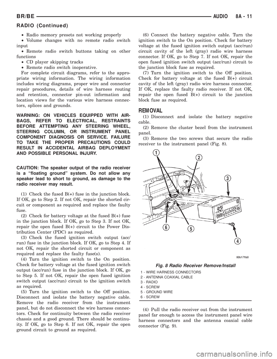
(3) Remove the two screws that secure the radio
receiver to the instrument panel (Fig. 8).
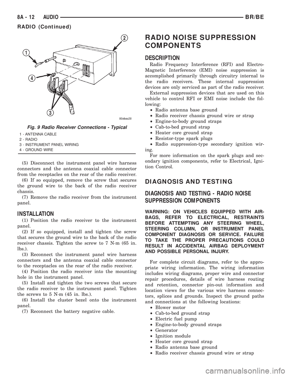
(4) Pull the radio receiver out from the instrument
panel far enough to access the instrument panel wire
harness connectors and the antenna coaxial cable
connector (Fig. 9).
Fig. 8 Radio Receiver Remove/Install
1 - WIRE HARNESS CONNECTORS
2 - ANTENNA COAXIAL CABLE
3 - RADIO
4 - SCREW
5 - GROUND WIRE
6 - SCREW
BR/BEAUDIO 8A - 11
RADIO (Continued)
Page 435 of 2889

(5) Disconnect the instrument panel wire harness
connectors and the antenna coaxial cable connector
from the receptacles on the rear of the radio receiver.
(6) If so equipped, remove the screw that secures
the ground wire to the back of the radio receiver
chassis.
(7) Remove the radio receiver from the instrument
panel.
INSTALLATION
(1) Position the radio receiver to the instrument
panel.
(2) If so equipped, install and tighten the screw
that secures the ground wire to the back of the radio
receiver chassis. Tighten the screw to 7 N´m (65 in.
lbs.).
(3) Reconnect the instrument panel wire harness
connectors and the antenna coaxial cable connector
to the receptacles on the rear of the radio receiver.
(4) Position the radio receiver into the mounting
hole in the instrument panel.
(5) Install and tighten the two screws that secure
the radio receiver to the instrument panel. Tighten
the screws to 5 N´m (45 in. lbs.).
(6) Install the cluster bezel onto the instrument
panel.
(7) Reconnect the battery negative cable.
RADIO NOISE SUPPRESSION
COMPONENTS
DESCRIPTION
Radio Frequency Interference (RFI) and Electro-
Magnetic Interference (EMI) noise suppression is
accomplished primarily through circuitry internal to
the radio receivers. These internal suppression
devices are only serviced as part of the radio receiver.
External suppression devices that are used on this
vehicle to control RFI or EMI noise include the fol-
lowing:
²Radio antenna base ground
²Radio receiver chassis ground wire or strap
²Engine-to-body ground straps
²Cab-to-bed ground strap
²Heater core ground strap
²Resistor-type spark plugs
²Radio suppression-type secondary ignition wir-
ing.
For more information on the spark plugs and sec-
ondary ignition components, refer to Electrical, Igni-
tion Control.
DIAGNOSIS AND TESTING
DIAGNOSIS AND TESTING - RADIO NOISE
SUPPRESSION COMPONENTS
WARNING: ON VEHICLES EQUIPPED WITH AIR-
BAGS, REFER TO ELECTRICAL, RESTRAINTS
BEFORE ATTEMPTING ANY STEERING WHEEL,
STEERING COLUMN, OR INSTRUMENT PANEL
COMPONENT DIAGNOSIS OR SERVICE. FAILURE
TO TAKE THE PROPER PRECAUTIONS COULD
RESULT IN ACCIDENTAL AIRBAG DEPLOYMENT
AND POSSIBLE PERSONAL INJURY.
For complete circuit diagrams, refer to the appro-
priate wiring information. The wiring information
includes wiring diagrams, proper wire and connector
repair procedures, details of wire harness routing
and retention, connector pin-out information and
location views for the various wire harness connec-
tors, splices and grounds. Inspect the ground paths
and connections at the following locations:
²Blower motor
²Cab-to-bed ground strap
²Electric fuel pump
²Engine-to-body ground straps
²Generator
²Ignition module
²Heater core ground strap
²Radio antenna base ground
²Radio receiver chassis ground wire or strap
Fig. 9 Radio Receiver Connections - Typical
1 - ANTENNA CABLE
2 - RADIO
3 - INSTRUMENT PANEL WIRING
4 - GROUND WIRE
8A - 12 AUDIOBR/BE
RADIO (Continued)
Page 446 of 2889

CHIME/BUZZER
TABLE OF CONTENTS
page page
CHIME WARNING SYSTEM
DESCRIPTION............................1
OPERATION.............................1DIAGNOSIS AND TESTING..................2
CHIME WARNING SYSTEM................2
CHIME WARNING SYSTEM
DESCRIPTION
A chime warning system is standard factory-in-
stalled equipment on this model. The chime warning
system uses a single chime tone generator that is
integral to the Central Timer Module (CTM) to pro-
vide an audible indication of various vehicle condi-
tions that may require the attention of the vehicle
operator. The chime warning system includes the fol-
lowing major components, which are described in fur-
ther detail elsewhere in this service manual:
²Central Timer Module- The Central Timer
Module (CTM) is located under the driver side end of
the instrument panel, inboard of the instrument
panel steering column opening. The CTM contains an
integral chime tone generator to provide all of the
proper chime warning system features based upon
the monitored inputs.
²Door Ajar Switch- A door ajar switch is inte-
gral to the driver side front door latch. This switch
provides an input to the chime warning system indi-
cating whether the driver side front door is open or
closed.
²Headlamp Switch- The headlamp switch is
located on the instrument panel outboard of the
steering column. The headlamp switch provides an
input to the chime warning system indicating when
the exterior lamps are turned On or Off.
²Ignition Switch- A key-in ignition switch is
integral to the ignition switch. The key-in ignition
switch provides an input to the chime warning sys-
tem indicating whether a key is present in the igni-
tion lock cylinder.
²Seat Belt Switch- A seat belt switch is inte-
gral to the driver side front seat belt retractor unit.
The seat belt switch provides an input to the chime
warning system indicating whether the driver side
front seat belt is fastened.
Hard wired circuitry connects many of the chime
warning system components to each other through
the electrical system of the vehicle. These hard wired
circuits are integral to several wire harnesses, which
are routed throughout the vehicle and retained bymany different methods. These circuits may be con-
nected to each other, to the vehicle electrical system
and to the chime warning system components
through the use of a combination of soldered splices,
splice block connectors, and many different types of
wire harness terminal connectors and insulators.
Refer to the appropriate wiring information. The wir-
ing information includes wiring diagrams, proper
wire and connector repair procedures, further details
on wire harness routing and retention, as well as
pin-out and location views for the various wire har-
ness connectors, splices and grounds.
The CTM chime warning system circuitry and the
integral chime tone generator cannot be adjusted or
repaired. If the CTM or the chime tone generator are
damaged or faulty, the CTM unit must be replaced.
OPERATION
The chime warning system is designed to provide an
audible output as an indication of various conditions
that may require the attention or awareness of the
vehicle operator. The chime warning system compo-
nents operate on battery current received through a
fused B(+) fuse in the Junction Block (JB) on a non-
switched fused B(+) circuit so that the system may
operate regardless of the ignition switch position.
The chime warning system provides an audible
indication to the vehicle operator under the following
conditions:
²Fasten Seat Belt Warning- The Central
Timer Module (CTM) chime tone generator will gen-
erate repetitive chime tones at a slow rate to
announce that a hard wired input from the seat belt
switch to the Electro-Mechanical Instrument Cluster
(EMIC) indicates that the driver side front seat belt
is not fastened with the ignition switch in the On
position. Unless the driver side front seat belt is fas-
tened, the chimes will continue to sound for a dura-
tion of about seven seconds each time the ignition
switch is turned to the On position or until the driver
side front seat belt is fastened, whichever occurs
first. This chime tone is based upon a hard wired
chime request input to the CTM from the EMIC, but
is not related to the operation of the EMIC ªSeatbeltº
indicator.
BR/BECHIME/BUZZER 8B - 1