2001 DODGE RAM tow bar
[x] Cancel search: tow barPage 46 of 2889
down several times. Always release the bumper in
the down position.Set the front end alignment to
specifications while the vehicle is in its NOR-
MALLY LOADED CONDITION.
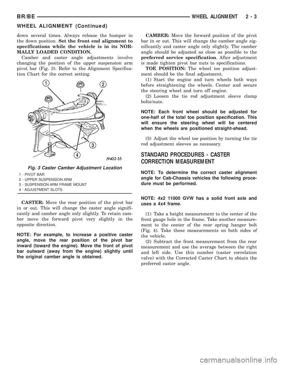
Camber and caster angle adjustments involve
changing the position of the upper suspension arm
pivot bar (Fig. 3). Refer to the Alignment Specifica-
tion Chart for the correct setting.
CASTER:Move the rear position of the pivot bar
in or out. This will change the caster angle signifi-
cantly and camber angle only slightly. To retain cam-
ber move the forward pivot very slightly in the
opposite direction.
NOTE: For example, to increase a positive caster
angle, move the rear position of the pivot bar
inward (toward the engine). Move the front of pivot
bar outward (away from the engine) slightly until
the original camber angle is obtained.CAMBER:Move the forward position of the pivot
bar in or out. This will change the camber angle sig-
nificantly and caster angle only slightly. The camber
angle should be adjusted as close as possible to the
preferred service specification. After adjustment
is made tighten pivot bar nuts to specifications.
TOE POSITION:The wheel toe position adjust-
ment should be the final adjustment.
(1) Start the engine and turn wheels both ways
before straightening the wheels. Center and secure
the steering wheel and turn off engine.
(2) Loosen the tie rod adjustment sleeve clamp
bolts/nuts.
NOTE: Each front wheel should be adjusted for
one-half of the total toe position specification. This
will ensure the steering wheel will be centered
when the wheels are positioned straight-ahead.
(3) Adjust the wheel toe position by turning the tie
rod adjustment sleeves as necessary.
STANDARD PROCEDURES - CASTER
CORRECTION MEASUREMENT
NOTE: To determine the correct caster alignment
angle for Cab-Chassis vehicles the following proce-
dure must be performed.
NOTE: 4x2 11000 GVW has a solid front axle and
uses a 4x4 frame.
(1) Take a height measurement to the center of the
front gauge hole in the frame. Take another measure-
ment to the center of the rear spring hanger bolt
(Fig. 4). Take these measurements on both sides of
the vehicle.
(2) Subtract the front measurement from the rear
measurement and use the average between the right
and left side. Use this number (caster correlation
valve) with the Corrected Caster Chart to obtain the
preferred caster angle.
Fig. 3 Caster Camber Adjustment Location
1 - PIVOT BAR
2 - UPPER SUSPENSION ARM
3 - SUSPENSION ARM FRAME MOUNT
4 - ADJUSTMENT SLOTS
BR/BEWHEEL ALIGNMENT 2 - 3
WHEEL ALIGNMENT (Continued)
Page 379 of 2889
(4) Install fan blade/viscous fan drive assembly to
water pump shaft (Fig. 6).
(5) Except 8.0L V-10 Engine: Install coolant
reserve/overflow tank to fan shroud. Snaps into posi-
tion.
(6) Install throttle cable to fan shroud.
(7) Connect negative battery cable.
NOTE: Viscous Fan Drive Fluid Pump Out Require-
ment: After installing a new viscous fan drive, bring
the engine speed up to approximately 2000 rpm and
hold for approximately two minutes. This will
ensure proper fluid distribution within the drive.
RADIATOR FAN - 5.9L DIESEL
REMOVAL
CAUTION: If the viscous fan drive is replaced
because of mechanical damage, the cooling fan
blades should also be inspected. Inspect for fatigue
cracks, loose blades, or loose rivets that could
have resulted from excessive vibration. Replace fan
blade assembly if any of these conditions are
found. Also inspect water pump bearing and shaft
assembly for any related damage due to a viscous
fan drive malfunction.
(1) Disconnect the battery negative cables.
(2) Remove the fan shroud mounting bolts. Posi-
tion fan shroud towards engine.
CAUTION: Do not remove the fan pulley bolts. This
pulley is under spring tension.
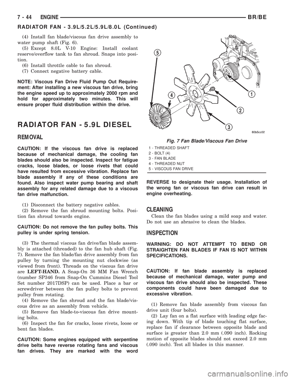
(3) The thermal viscous fan drive/fan blade assem-
bly is attached (threaded) to the fan hub shaft (Fig.
7). Remove the fan blade/fan drive assembly from fan
pulley by turning the mounting nut clockwise (as
viewed from front). Threads on the viscous fan drive
areLEFT-HAND.A Snap-On 36 MM Fan Wrench
(number SP346 from Snap-On Cummins Diesel Tool
Set number 2017DSP) can be used. Place a bar or
screwdriver between the fan pulley bolts to prevent
pulley from rotating.
(4) Remove the fan shroud and the fan blade/vis-
cous drive as an assembly from vehicle.
(5) Remove fan blade-to-viscous fan drive mount-
ing bolts.
(6) Inspect the fan for cracks, loose rivets, loose or
bent fan blades.
CAUTION: Some engines equipped with serpentine
drive belts have reverse rotating fans and viscous
fan drives. They are marked with the wordREVERSE to designate their usage. Installation of
the wrong fan or viscous fan drive can result in
engine overheating.
CLEANING
Clean the fan blades using a mild soap and water.
Do not use an abrasive to clean the blades.
INSPECTION
WARNING: DO NOT ATTEMPT TO BEND OR
STRAIGHTEN FAN BLADES IF FAN IS NOT WITHIN
SPECIFICATIONS.
CAUTION: If fan blade assembly is replaced
because of mechanical damage, water pump and
viscous fan drive should also be inspected. These
components could have been damaged due to
excessive vibration.
(1) Remove fan blade assembly from viscous fan
drive unit (four bolts).
(2) Lay fan on a flat surface with leading edge fac-
ing down. With tip of blade touching flat surface,
replace fan if clearance between opposite blade and
surface is greater than 2.0 mm (.090 inch). Rocking
motion of opposite blades should not exceed 2.0 mm
(.090 inch). Test all blades in this manner.
Fig. 7 Fan Blade/Viscous Fan Drive
1 - THREADED SHAFT
2 - BOLT (4)
3 - FAN BLADE
4 - THREADED NUT
5 - VISCOUS FAN DRIVE
7 - 44 ENGINEBR/BE
RADIATOR FAN - 3.9L/5.2L/5.9L/8.0L (Continued)
Page 732 of 2889
be routed away from hot, sharp, or moving parts;
and, sharp bends that might pinch the hose must be
avoided.
WASHER NOZZLE
DESCRIPTION
The two washer nozzles have integral snap fea-
tures that secure them in dedicated holes in the cowl
plenum cover/grille panel located near the base of the
windshield. The domed upper surface of the washer
nozzle is visible on the top of the plenum cover/grille
panel, and the nozzle orifice is oriented towards the
windshield glass. The washer plumbing fittings for
the washer nozzles are concealed beneath the cowl
plenum cover/grille panel. These fluidic washer noz-
zles are constructed of molded plastic. The cowl ple-
num cover/grille panel must be removed from the
vehicle to access the nozzles for service. The washer
nozzles cannot be adjusted or repaired and, if faulty
or damaged, they must be replaced.
OPERATION
The two washer nozzles are designed to dispense
washer fluid into the wiper pattern area on the out-
side of the windshield glass. Pressurized washer fluid
is fed to each nozzle from the washer reservoir by the
washer pump/motor through rubber hoses, which are
attached to a barbed nipple on each washer nozzle
below the cowl plenum cover/grille panel. The washer
nozzles incorporate a fluidic design, which causes the
nozzle to emit the pressurized washer fluid as an
oscillating stream to more effectively cover a larger
area of the glass area to be cleaned.
REMOVAL
(1) Remove the cowl plenum cover/grille panel
from the cowl top. (Refer to 23 - BODY/EXTERIOR/
COWL GRILLE - REMOVAL).
(2) From the underside of the cowl plenum cover/
grille panel, disconnect the washer hose from the
nozzle fitting.
(3) From the underside of the cowl plenum cover/
grille panel, compress the snap features of the
washer nozzle and push the nozzle out through the
top of the panel.
INSTALLATION
(1) From the top of the cowl plenum cover/grille
panel, insert the barbed nipple of the washer nozzle
through the nozzle mounting hole.
(2) With the orifice of the washer nozzle oriented
toward the windshield, use hand pressure to push
the nozzle into the mounting hole until the snap fea-tures of the nozzle are fully engaged with the under-
side of the cowl plenum cover/grille panel.
(3) From the underside of the cowl plenum cover/
grille panel, reconnect the washer hose to the washer
nozzle fitting.
(4) Reinstall the cowl plenum cover/grille panel
onto the cowl top. (Refer to 23 - BODY/EXTERIOR/
COWL GRILLE - INSTALLATION).
WASHER PUMP/MOTOR
DESCRIPTION
The washer pump/motor unit is located on the rear
of the washer reservoir, near the bottom in the left
front corner of the engine compartment. A small per-
manently lubricated and sealed electric motor is cou-
pled to the rotor-type washer pump. A seal flange
with a large barbed inlet nipple on the pump housing
passes through a rubber grommet seal installed in
the dedicated mounting hole near the bottom of the
washer reservoir. A smaller barbed outlet nipple on
the pump housing connects the unit to the washer
hose. The washer pump/motor unit is retained on the
reservoir by the interference fit between the barbed
pump inlet nipple and the grommet seal, which is a
light press fit. An integral electrical connector recep-
tacle is located on the motor housing. The washer
pump/motor unit cannot be repaired. If faulty or
damaged, the entire washer pump/motor unit must
be replaced.
OPERATION
The washer pump/motor unit is connected to the
vehicle electrical system through a single take out
and two-cavity connector of the headlamp and dash
wire harness. The washer pump/motor is grounded at
all times through a take out of the headlamp and
dash wire harness with a single eyelet terminal con-
nector that is secured by a nut to a ground stud
located on the forward extension of the left front
fender wheel housing in the engine compartment.
The washer pump/motor receives battery current on
a fused ignition switch output (run-acc) circuit
through the closed contacts of the momentary washer
switch within the multi-function switch only when
the washer button on the end of the switch control
stalk is depressed towards the steering column.
Washer fluid is gravity-fed from the washer reservoir
to the inlet side of the washer pump. When the pump
motor is energized, the rotor-type pump pressurizes
the washer fluid and forces it through the pump out-
let nipple, the washer plumbing, and the washer noz-
zles onto the windshield glass.
BR/BEWIPERS/WASHERS 8R - 9
WASHER HOSES/TUBES (Continued)
Page 756 of 2889

8W-02 COMPONENT INDEX
Component Page
4WD Switch.......................... 8W-31
A/C Compressor Clutch Relay............ 8W-42
A/C Compressor Clutch................. 8W-42
A/C-Heater Control.................... 8W-42
A/C Heater Temperature Select........... 8W-42
A/C High Pressure Switch............... 8W-42
A/C Low Pressure Switch................ 8W-42
Accelerator Pedal Position Sensor......... 8W-30
Aftermarket Center High Mounted
Stop Lamp......................... 8W-51
Aftermarket Trailer Tow Connector........ 8W-54
Airbag Control Module.................. 8W-43
Ambient Temperature Sensor............ 8W-49
Ash Receiver Lamp.................... 8W-44
Automatic Day/Night Mirror............. 8W-49
Automatic Shut Down Relay............. 8W-30
Auxiliary Battery...................... 8W-20
Back-Up Lamp Switch.................. 8W-51
Back-Up Lamps....................... 8W-51
Battery Temperature Sensor............. 8W-30
Battery............................. 8W-20
Blend Door Actuator................... 8W-42
Blower Motor Relay.................... 8W-42
Blower Motor Resistor Block............. 8W-42
Blower Motor......................... 8W-42
Brake Lamp Switch.................... 8W-51
Brake Pressure Switch............... 8W-34, 35
Bypass Jumper....................... 8W-21
Camshaft Position Sensor............... 8W-30
Capacitor......................... 8W-10, 30
Cargo Lamps......................... 8W-44
Center High Mounted Stop Lamps........ 8W-51
Center Identification Lamp.............. 8W-50
Central Timer Module.................. 8W-45
Cigar Lighter......................... 8W-41
Circuit Breakers...................... 8W-12
Clockspring.................. 8W-33, 41, 43, 47
Clutch Pedal Position Switch............. 8W-21
Combination Flasher................... 8W-52
Controller Antilock Brake............ 8W-34, 35
Crankshaft Position Sensor.............. 8W-30
Cummins Bus........................ 8W-18
Cup Holder Lamp..................... 8W-44
Cylinder Lock Switches................ 8W-39
Data Link Connector................... 8W-18
Daytime Running Lamp Module.......... 8W-50
Dome Lamp.......................... 8W-44
Door Ajar Switches.................... 8W-45
Door Lock Motors..................... 8W-61
Door Window/Lock Switches.......... 8W-60, 61
Driver Airbag......................... 8W-43
Duty Cycle EVAP/Purge Solenoid......... 8W-30Component Page
Electric Brake Provision................ 8W-54
Engine Control Module.............. 8W-30, 70
Engine Coolant Temperature Sensor....... 8W-30
Engine Oil Pressure Sensor.............. 8W-30
Engine Starter Motor Relay.............. 8W-21
Engine Starter Motor................... 8W-21
Fender Lamp......................... 8W-51
Fog Lamp Indicator.................... 8W-50
Fog Lamp Relay....................... 8W-50
Fog Lamp............................ 8W-50
Fuel Heater Relay..................... 8W-30
Fuel Heater.......................... 8W-30
Fuel Injection Pump................... 8W-30
Fuel Injectors......................... 8W-30
Fuel Transfer Pump.................... 8W-30
Fuses (JB)........................... 8W-12
Fuses (PDC).......................... 8W-10
Fusible Link....................... 8W-20, 30
Generator............................ 8W-20
Glove Box Lamp And Switch............. 8W-44
Grounds............................. 8W-15
Headlamp Beam Select Switch........... 8W-50
Headlamp Switch...................... 8W-50
Headlamp........................... 8W-50
Heated Mirror Relay................... 8W-62
Heated Mirror Switch.................. 8W-62
Heated Seat Cushions.................. 8W-63
Heated Seat Relay..................... 8W-12
Heated Seat Switches.................. 8W-63
High Beam Indicator................... 8W-40
High Note Horn....................... 8W-41
Horn Relay.......................... 8W-41
Horn Switch.......................... 8W-41
Idle Air Control Motor.................. 8W-30
Ignition Coil 4-Pack.................... 8W-30
Ignition Coil 6-Pack.................... 8W-30
Ignition Coil.......................... 8W-30
Ignition Switch....................... 8W-10
Instrument Cluster.................... 8W-40
Intake Air Heater Relays................ 8W-30
Intake Air Heater..................... 8W-30
Intake Air Temperature Sensor........... 8W-30
Intermittent Wiper Switch............... 8W-53
Joint Connectors . . 8W-10, 12, 15, 30, 31, 34, 35, 40,
44, 45, 51, 53, 70
Junction Block........................ 8W-12
Leak Detection Pump.................. 8W-30
License Lamp......................... 8W-51
Low Note Horn....................... 8W-41
Lumbar Motors....................... 8W-63
Manifold Absolute Pressure Sensor........ 8W-30
Manifold Air Pressure Sensor............ 8W-30
BR/BE8W-02 COMPONENT INDEX 8W - 02 - 1
Page 1016 of 2889
Component Page
Left Speed Control Switch............ 8W-80-58
Left Tail/Stop/Turn Signal Lamp........ 8W-80-58
Left Tweeter (Premium).............. 8W-80-58
Left Visor/Vanity Lamp............... 8W-80-58
Low Note Horn..................... 8W-80-58
Manifold ABSolute Pressure Sensor
(3.9L/5.2L/5.9L)................... 8W-80-58
Manifold ABSolute Pressure Sensor
(8.0L).......................... 8W-80-59
Manifold Air Pressure Sensor (Diesel).... 8W-80-59
Multi-Function Switch............... 8W-80-59
Output Speed Sensor................ 8W-80-59
Overdrive Switch................... 8W-80-60
Overhead Console (Base).............. 8W-80-60
Overhead Console (Highline)........... 8W-80-60
Oxygen Sensor 1/1 Left Bank Up
(5.9L HD/8.0L)................... 8W-80-60
Oxygen Sensor 1/1 Left Bank Up
(California)...................... 8W-80-60
Oxygen Sensor 1/1 Upstream
(A/T Except 8.0L)................. 8W-80-61
Oxygen Sensor 1/1 Upstream
(M/T Except 8.0L)................. 8W-80-61
Oxygen Sensor 1/2 Downstream
(3.9L/5.2L)....................... 8W-80-61
Oxygen Sensor 1/2 Left Bank Down
(California)...................... 8W-80-61
Oxygen Sensor 1/2 Pre-Catalyst (8.0L) . . . 8W-80-61
Oxygen Sensor 1/3 Post Catalyst (8.0L) . . 8W-80-62
Oxygen Sensor 2/1 Right Bank Up (5.9L HD)
(5.2L/5.9L/8.0L California).......... 8W-80-62
Oxygen Sensor 2/2 Right Bank Down
(California)...................... 8W-80-62
Park/Neutral Position Switch
(A/T Except 8.0L)................. 8W-80-62
Park/Neutral Position Switch (A/T 8.0L) . . 8W-80-62
Passenger Airbag................... 8W-80-63
Passenger Airbag On/Off Switch C1..... 8W-80-63
Passenger Airbag On/Off Switch C2..... 8W-80-63
Passenger Cylinder Lock Switch........ 8W-80-63
Passenger Door Ajar Switch........... 8W-80-63
Passenger Door Lock Motor........... 8W-80-63
Passenger Door Window/Lock Switch.... 8W-80-64
Passenger Heated Seat Cushion........ 8W-80-64
Passenger Heated Seat Switch......... 8W-80-64
Passenger Lumbar Motor............. 8W-80-64
Passenger Power Seat Front Vertical Motor
(Club Cab)....................... 8W-80-64
Passenger Power Seat Horizontal Motor
(Club Cab)....................... 8W-80-65
Passenger Power Seat Rear Vertical Motor
(Club Cab)....................... 8W-80-65Component Page
Passenger Power Seat Switch
(Club Cab)....................... 8W-80-65
Passenger Power Window Motor........ 8W-80-65
Power Mirror Switch................. 8W-80-65
Power Outlet....................... 8W-80-66
Powertrain Control Module C1 (Diesel) . . . 8W-80-66
Powertrain Control Module C1 (Gas).... 8W-80-67
Powertrain Control Module C2 (Diesel) . . . 8W-80-67
Powertrain Control Module C2 (Gas).... 8W-80-68
Powertrain Control Module C3 (Diesel) . . . 8W-80-69
Powertrain Control Module C3 (Gas).... 8W-80-70
Radio C1.......................... 8W-80-70
Radio C2.......................... 8W-80-71
Radio C3.......................... 8W-80-71
Radio Choke Relay.................. 8W-80-71
Rear Wheel Speed Sensor (ABS)........ 8W-80-71
Right Back-Up Lamp................ 8W-80-71
Right Fog Lamp.................... 8W-80-72
Right Front Door Speaker (Premium).... 8W-80-72
Right Front Door Speaker (Standard).... 8W-80-72
Right Front Fender Lamp
(Dual Rear Wheels)................ 8W-80-72
Right Front Wheel Speed Sensor (ABS) . . 8W-80-72
Right Headlamp.................... 8W-80-73
Right License Lamp................. 8W-80-73
Right Outboard Clearance Lamp....... 8W-80-73
Right Outboard Headlamp............ 8W-80-73
Right Outboard Identification Lamp..... 8W-80-73
Right Park/Turn Signal Lamp.......... 8W-80-73
Right Power Mirror.................. 8W-80-74
Right Rear Fender Lamp
(Dual Rear Wheels)................ 8W-80-74
Right Rear Speaker (2 Door Premium) . . . 8W-80-74
Right Rear Speaker (4 Door Premium) . . . 8W-80-74
Right Rear Speaker (Standard 2 Door) . . . 8W-80-74
Right Rear Speaker (Standard 4 Door) . . . 8W-80-74
Right Remote Radio Switch........... 8W-80-75
Right Speed Control Switch........... 8W-80-75
Right Tail/Stop/Turn Signal Lamp...... 8W-80-75
Right Tweeter (Premium)............. 8W-80-75
Right Visor/Vanity Lamp.............. 8W-80-75
Seat Belt Switch (Club Cab)........... 8W-80-75
Seat Belt Switch (Standard Cab)....... 8W-80-76
Seat Heat Interface Module........... 8W-80-76
Speed Control Servo................. 8W-80-76
Tailgate Lamp (Dual Rear Wheels)...... 8W-80-76
Throttle Position Sensor (Gas)......... 8W-80-76
Trailer Tow Connector................ 8W-80-77
Transmission Solenoid Assembly........ 8W-80-77
Underhood Lamp................... 8W-80-77
Washer Fluid Level Switch............ 8W-80-77
Water In Fuel Sensor (Diesel).......... 8W-80-78
Wiper Motor....................... 8W-80-78
BR/BE8W-80 CONNECTOR PIN-OUTS 8W - 80 - 3
Page 1158 of 2889
(4) A controlled hone motor speed between 200 and
300 RPM is necessary to obtain the proper cross-
hatch angle. The number of up and down strokes per
minute can be regulated to get the desired 50É to 60É
angle. Faster up and down strokes increase the cross-
hatch angle.
(5) After honing, it is necessary that the block be
cleaned to remove all traces of abrasive. Use a brush
to wash parts with a solution of hot water and deter-
gent. Dry parts thoroughly. Use a clean, white, lint-
free cloth to check that the bore is clean. Oil the
bores after cleaning to prevent rusting.
STANDARD PROCEDUREÐHYDROSTATIC
LOCK
CAUTION: DO NOT use the starter motor to rotate
the crankshaft. Severe damage could occur.
When an engine is suspected of hydrostatic lock
(regardless of what caused the problem), follow the
steps below.
(1) Perform the Fuel Pressure Release Procedure
(Refer to 14 - FUEL SYSTEM/FUEL DELIVERY -
STANDARD PROCEDURE).
(2) Disconnect the negative cable(s) from the bat-
tery.
(3) Inspect air cleaner, induction system, and
intake manifold to ensure system is dry and clear of
foreign material.
(4) Place a shop towel around the spark plugs to
catch any fluid that may possibly be under pressure
in the cylinder head. Remove the spark plugs.
(5) With all spark plugs removed, rotate the crank-
shaft using a breaker bar and socket.
(6) Identify the fluid in the cylinders (coolant, fuel,
oil, etc.).
(7) Be sure all fluid has been removed from the
cylinders.
(8) Repair engine or components as necessary to
prevent this problem from occurring again.
(9) Squirt a small amount of engine oil into the
cylinders to lubricate the walls. This will prevent
damage on restart.
(10) Install new spark plugs. Tighten the spark
plugs to 41 N´m (30 ft. lbs.) torque.
(11) Drain engine oil. Remove and discard the oil
filter.
(12) Install the drain plug. Tighten the plug to 34
N´m (25 ft. lbs.) torque.
(13) Install a new oil filter.
(14) Fill engine crankcase with the specified
amount and grade of oil. (Refer to LUBRICATION &
MAINTENANCE - SPECIFICATIONS).
(15) Connect the negative cable(s) to the battery.
(16) Start the engine and check for any leaks.
STANDARD PROCEDUREÐREPAIR DAMAGED
OR WORN THREADS
CAUTION: Be sure that the tapped holes maintain
the original center line.
Damaged or worn threads can be repaired. Essen-
tially, this repair consists of:
²Drilling out worn or damaged threads.
²Tapping the hole with a special Heli-Coil Tap, or
equivalent.
²Installing an insert into the tapped hole to bring
the hole back to its original thread size.
STANDARD PROCEDUREÐFORM-IN-PLACE
GASKETS & SEALERS
There are numerous places where form-in-place
gaskets are used on the engine. Care must be taken
when applying form-in-place gaskets to assure
obtaining the desired results.Do not use form-in-
place gasket material unless specified.Bead size,
continuity, and location are of great importance. Too
thin a bead can result in leakage while too much can
result in spill-over which can break off and obstruct
fluid feed lines. A continuous bead of the proper
width is essential to obtain a leak-free gasket.
There are numerous types of form-in-place gasket
materials that are used in the engine area. Mopart
Engine RTV GEN II, MopartATF-RTV, and Mopart
Gasket Maker gasket materials, each have different
properties and can not be used in place of the other.
MOPARtENGINE RTV GEN II
MopartEngine RTV GEN II is used to seal com-
ponents exposed to engine oil. This material is a spe-
cially designed black silicone rubber RTV that
retains adhesion and sealing properties when
exposed to engine oil. Moisture in the air causes the
material to cure. This material is available in three
ounce tubes and has a shelf life of one year. After one
year this material will not properly cure. Always
inspect the package for the expiration date before
use.
MOPARtATF RTV
MopartATF RTV is a specifically designed black
silicone rubber RTV that retains adhesion and seal-
ing properties to seal components exposed to auto-
matic transmission fluid, engine coolants, and
moisture. This material is available in three ounce
tubes and has a shelf life of one year. After one year
this material will not properly cure. Always inspect
the package for the expiration date before use.
MOPARtGASKET MAKER
MopartGasket Maker is an anaerobic type gasket
material. The material cures in the absence of air
when squeezed between two metallic surfaces. It will
not cure if left in the uncovered tube. The anaerobic
BR/BEENGINE 3.9L 9 - 11
ENGINE 3.9L (Continued)
Page 1189 of 2889
lower rails. Insert oil rail spacer first, then side
rails.
(b) Install the second compression rings using
Installation Tool C-4184. The compression rings
must be installed with the identification mark face
up (toward top of piston) and chamfer facing down.
An identification mark on the ring is a drill point,
a stamped letter ªOº, an oval depression, or the
word ªTOPº (Fig. 41) (Fig. 43).
(c) Using a ring installer, install the top com-
pression ring with the chamfer facing up (Fig. 42)
(Fig. 43). An identification mark on the ring is a
drill point, a stamped letter ªOº, an oval depression
or the word ªTOPº facing up.
(d) Measure side clearance between piston ring
and ring land. Clearance should be 0.074-0.097 mm
(0.0029-0.0038 in.) for the compression rings. The
steel rail oil ring should be free in groove, but
should not exceed 0.246 mm (0.0097 in.) side clear-
ance.
(e) Pistons with insufficient, or excessive, side
clearance should be replaced.
(3) Orient the rings:
(a) Arrange top compression ring 90É counter-
clockwise from the oil ring rail gap (Fig. 44).
(b) Arrange second compression ring 90É clock-
wise from the oil ring rail gap (Fig. 44).
VIBRATION DAMPER
REMOVAL
(1) Disconnect the negative cable from the battery.
(2) Remove fan, and fan drive (Refer to 7 - COOL-
ING/ENGINE/FAN DRIVE VISCOUS CLUTCH -
REMOVAL).(3) Remove the accessory drive belt (Refer to 7 -
COOLING/ACCESSORY DRIVE/DRIVE BELTS -
REMOVAL).
(4) Remove the vibration damper pulley.
(5) Remove vibration damper bolt and washer from
end of crankshaft.
(6) Install bar and screw from Puller Tool Set
C-3688. Install two bolts with washers through the
puller tool and into the vibration damper (Fig. 45).
(7) Pull vibration damper off of the crankshaft.
INSTALLATION
(1) Position the vibration damper onto the crank-
shaft.
(2) Place installing tool, part of Puller Tool Set
C-3688, in position and press the vibration damper
onto the crankshaft (Fig. 46).
Fig. 41 Second Compression Ring Identification
(Typical)
1 - SECOND COMPRESSION RING (BLACK CAST IRON)
2 - CHAMFER
3 - TWO DOTS
Fig. 42 Top Compression Ring Identification
(Typical)
1 - TOP COMPRESSION RING (GRAY IN COLOR)
2 - CHAMFER
3 - ONE DOT
Fig. 43 Compression Ring Chamfer Location
(Typical)
1 - CHAMFER
2 - TOP COMPRESSION RING
3 - SECOND COMPRESSION RING
4 - PISTON
5 - CHAMFER
9 - 42 ENGINE 3.9LBR/BE
PISTON RINGS (Continued)
Page 1216 of 2889
(1) Perform the Fuel Pressure Release Procedure
(Refer to 14 - FUEL SYSTEM/FUEL DELIVERY -
STANDARD PROCEDURE).
(2) Disconnect the negative cable(s) from the bat-
tery.
(3) Inspect air cleaner, induction system, and
intake manifold to ensure system is dry and clear of
foreign material.
(4) Place a shop towel around the spark plugs to
catch any fluid that may possibly be under pressure
in the cylinder head. Remove the spark plugs.
(5) With all spark plugs removed, rotate the crank-
shaft using a breaker bar and socket.
(6) Identify the fluid in the cylinders (coolant, fuel,
oil, etc.).
(7) Be sure all fluid has been removed from the
cylinders.
(8) Repair engine or components as necessary to
prevent this problem from occurring again.
(9) Squirt a small amount of engine oil into the
cylinders to lubricate the walls. This will prevent
damage on restart.
(10) Install new spark plugs. Tighten the spark
plugs to 41 N´m (30 ft. lbs.) torque.
(11) Drain engine oil. Remove and discard the oil
filter.
(12) Install the drain plug. Tighten the plug to 34
N´m (25 ft. lbs.) torque.
(13) Install a new oil filter.
(14) Fill engine crankcase with the specified
amount and grade of oil. (Refer to LUBRICATION &
MAINTENANCE - SPECIFICATIONS).
(15) Connect the negative cable(s) to the battery.
(16) Start the engine and check for any leaks.
STANDARD PROCEDUREÐCYLINDER BORE
HONING
Before honing, stuff plenty of clean shop towels
under the bores and over the crankshaft to keep
abrasive materials from entering the crankshaft
area.
(1) Used carefully, the Cylinder Bore Sizing Hone
C-823, equipped with 220 grit stones, is the best tool
for this job. In addition to deglazing, it will reduce
taper and out-of-round, as well as removing light
scuffing, scoring and scratches. Usually, a few strokes
will clean up a bore and maintain the required lim-
its.
CAUTION: DO NOT use rigid type hones to remove
cylinder wall glaze.
(2) Deglazing of the cylinder walls may be done if
the cylinder bore is straight and round. Use a cylin-
der surfacing hone, Honing Tool C-3501, equipped
with 280 grit stones (C-3501-3810). about 20-60strokes, depending on the bore condition, will be suf-
ficient to provide a satisfactory surface. Using honing
oil C-3501-3880, or a light honing oil, available from
major oil distributors.
CAUTION: DO NOT use engine or transmission oil,
mineral spirits, or kerosene.
(3) Honing should be done by moving the hone up
and down fast enough to get a crosshatch pattern.
The hone marks should INTERSECT at 50É to 60É
for proper seating of rings (Fig. 3).
(4) A controlled hone motor speed between 200 and
300 RPM is necessary to obtain the proper cross-
hatch angle. The number of up and down strokes per
minute can be regulated to get the desired 50É to 60É
angle. Faster up and down strokes increase the cross-
hatch angle.
(5) After honing, it is necessary that the block be
cleaned to remove all traces of abrasive. Use a brush
to wash parts with a solution of hot water and deter-
gent. Dry parts thoroughly. Use a clean, white, lint-
free cloth to check that the bore is clean. Oil the
bores after cleaning to prevent rusting.
REMOVAL
(1) Disconnect the battery negative cable.
(2) Drain cooling system (Refer to 7 - COOLING -
STANDARD PROCEDURE).
(3) Recover refrigerant from a/c system, if
equipped (Refer to 24 - HEATING & AIR CONDI-
TIONING/PLUMBING - STANDARD PROCEDURE).
(4) Remove the a/c condenser, if equipped (Refer to
24 - HEATING & AIR CONDITIONING/PLUMBING/
A/C CONDENSER - REMOVAL).
Fig. 3 Cylinder Bore Crosshatch Pattern
1 - CROSSHATCH PATTERN
2 - INTERSECT ANGLE
BR/BEENGINE 5.2L 9 - 69
ENGINE 5.2L (Continued)