2001 DODGE RAM air bleeding
[x] Cancel search: air bleedingPage 278 of 2889
front tire (bruised, ply separation) can also cause
pull.
A common and frequently misdiagnosed pull condi-
tion is where direction of pull changes after a few
stops. The cause is a combination of brake drag fol-
lowed by fade at one of the brake units.
As the dragging brake overheats, efficiency is so
reduced that fade occurs. Since the opposite brake
unit is still functioning normally, its braking effect is
magnified. This causes pull to switch direction in
favor of the normally functioning brake unit.
An additional point when diagnosing a change in
pull condition concerns brake cool down. Remember
that pull will return to the original direction, if the
dragging brake unit is allowed to cool down (and is
not seriously damaged).
REAR BRAKE GRAB OR PULL
Rear grab or pull is usually caused by improperly
adjusted or seized parking brake cables, contami-
nated lining, bent or binding shoes and support
plates, or improperly assembled components. This is
particularly true when only one rear wheel is
involved. However, when both rear wheels are
affected, the master cylinder or proportioning valve
could be at fault.
BRAKES DO NOT HOLD AFTER DRIVING THROUGH DEEP
WATER PUDDLES
This condition is generally caused by water soaked
lining. If the lining is only wet, it can be dried by
driving with the brakes very lightly applied for a
mile or two. However, if the lining is both soaked and
dirt contaminated, cleaning and/or replacement will
be necessary.
BRAKE LINING CONTAMINATION
Brake lining contamination is mostly a product of
leaking calipers or wheel cylinders, worn seals, driv-
ing through deep water puddles, or lining that has
become covered with grease and grit during repair.
Contaminated lining should be replaced to avoid fur-
ther brake problems.
WHEEL AND TIRE PROBLEMS
Some conditions attributed to brake components
may actually be caused by a wheel or tire problem.
A damaged wheel can cause shudder, vibration and
pull. A worn or damaged tire can also cause pull.
Severely worn tires with very little tread left can
produce a grab-like condition as the tire loses and
recovers traction. Flat-spotted tires can cause vibra-
tion and generate shudder during brake operation. A
tire with internal damage such as a severe bruise,
cut, or ply separation can cause pull and vibration.BRAKE NOISES
Some brake noise is common with rear drum
brakes and on some disc brakes during the first few
stops after a vehicle has been parked overnight or
stored. This is primarily due to the formation of trace
corrosion (light rust) on metal surfaces. This light
corrosion is typically cleared from the metal surfaces
after a few brake applications causing the noise to
subside.
BRAKE SQUEAK/SQUEAL
Brake squeak or squeal may be due to linings that
are wet or contaminated with brake fluid, grease, or
oil. Glazed linings and rotors with hard spots can
also contribute to squeak. Dirt and foreign material
embedded in the brake lining will also cause squeak/
squeal.
A very loud squeak or squeal is frequently a sign of
severely worn brake lining. If the lining has worn
through to the brake shoes in spots, metal-to-metal
contact occurs. If the condition is allowed to continue,
rotors and drums can become so scored that replace-
ment is necessary.
BRAKE CHATTER
Brake chatter is usually caused by loose or worn
components, or glazed/burnt lining. Rotors with hard
spots can also contribute to chatter. Additional causes
of chatter are out-of-tolerance rotors, brake lining not
securely attached to the shoes, loose wheel bearings
and contaminated brake lining.
THUMP/CLUNK NOISE
Thumping or clunk noises during braking are fre-
quentlynotcaused by brake components. In many
cases, such noises are caused by loose or damaged
steering, suspension, or engine components. However,
calipers that bind on the slide surfaces can generate
a thump or clunk noise. In addition, worn out,
improperly adjusted, or improperly assembled rear
brake shoes can also produce a thump noise.
STANDARD PROCEDURE - MANUAL BLEEDING
Use Mopar brake fluid, or an equivalent quality
fluid meeting SAE J1703-F and DOT 3 standards
only. Use fresh, clean fluid from a sealed container at
all times.
(1) Remove reservoir filler caps and fill reservoir.
(2) If calipers, or wheel cylinders were overhauled,
open all caliper and wheel cylinder bleed screws.
Then close each bleed screw as fluid starts to drip
from it. Top off master cylinder reservoir once more
before proceeding.
(3) Attach one end of bleed hose to bleed screw
and insert opposite end in glass container partially
BR/BEBRAKES 5 - 7
HYDRAULIC/MECHANICAL (Continued)
Page 279 of 2889
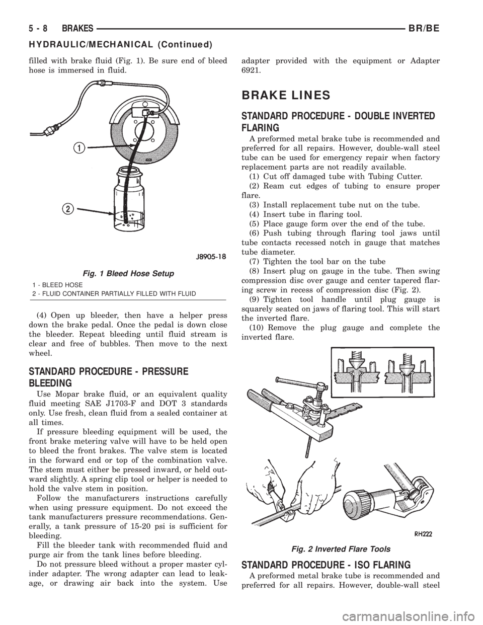
filled with brake fluid (Fig. 1). Be sure end of bleed
hose is immersed in fluid.
(4) Open up bleeder, then have a helper press
down the brake pedal. Once the pedal is down close
the bleeder. Repeat bleeding until fluid stream is
clear and free of bubbles. Then move to the next
wheel.
STANDARD PROCEDURE - PRESSURE
BLEEDING
Use Mopar brake fluid, or an equivalent quality
fluid meeting SAE J1703-F and DOT 3 standards
only. Use fresh, clean fluid from a sealed container at
all times.
If pressure bleeding equipment will be used, the
front brake metering valve will have to be held open
to bleed the front brakes. The valve stem is located
in the forward end or top of the combination valve.
The stem must either be pressed inward, or held out-
ward slightly. A spring clip tool or helper is needed to
hold the valve stem in position.
Follow the manufacturers instructions carefully
when using pressure equipment. Do not exceed the
tank manufacturers pressure recommendations. Gen-
erally, a tank pressure of 15-20 psi is sufficient for
bleeding.
Fill the bleeder tank with recommended fluid and
purge air from the tank lines before bleeding.
Do not pressure bleed without a proper master cyl-
inder adapter. The wrong adapter can lead to leak-
age, or drawing air back into the system. Useadapter provided with the equipment or Adapter
6921.
BRAKE LINES
STANDARD PROCEDURE - DOUBLE INVERTED
FLARING
A preformed metal brake tube is recommended and
preferred for all repairs. However, double-wall steel
tube can be used for emergency repair when factory
replacement parts are not readily available.
(1) Cut off damaged tube with Tubing Cutter.
(2) Ream cut edges of tubing to ensure proper
flare.
(3) Install replacement tube nut on the tube.
(4) Insert tube in flaring tool.
(5) Place gauge form over the end of the tube.
(6) Push tubing through flaring tool jaws until
tube contacts recessed notch in gauge that matches
tube diameter.
(7) Tighten the tool bar on the tube
(8) Insert plug on gauge in the tube. Then swing
compression disc over gauge and center tapered flar-
ing screw in recess of compression disc (Fig. 2).
(9) Tighten tool handle until plug gauge is
squarely seated on jaws of flaring tool. This will start
the inverted flare.
(10) Remove the plug gauge and complete the
inverted flare.
STANDARD PROCEDURE - ISO FLARING
A preformed metal brake tube is recommended and
preferred for all repairs. However, double-wall steel
Fig. 1 Bleed Hose Setup
1 - BLEED HOSE
2 - FLUID CONTAINER PARTIALLY FILLED WITH FLUID
Fig. 2 Inverted Flare Tools
5 - 8 BRAKESBR/BE
HYDRAULIC/MECHANICAL (Continued)
Page 290 of 2889
STANDARD PROCEDURE - BLEEDING
The hydraulic booster is generally self-bleeding,
this procedure will normally bleed the air from the
booster. Normal driving and operation of the unit will
remove any remaining trapped air.
(1) Fill power steering pump reservoir.
(2) Disconnect fuel shutdown relay and crank the
engine for several seconds, Refer to Fuel System for
relay location and WARNING.
(3) Check fluid level and add if necessary.
(4) Connect fuel shutdown relay and start the
engine.
(5) Turn the steering wheel slowly from lock to
lock twice.
(6) Stop the engine and discharge the accumulator
by depressing the brake pedal 5 times.
(7) Start the engine and turn the steering wheel
slowly from lock to lock twice.
(8) Turn off the engine and check fluid level and
add if necessary.
NOTE: If fluid foaming occurs, wait for foam to dis-
sipate and repeat steps 7 and 8.
REMOVAL
NOTE: If the booster is being replaced because the
power steering fluid is contaminated, flush the
power steering system before replacing the booster.
(1) With engine off depress the brake pedal 5
times to discharge the accumulator.
(2) Remove brake lines from master cylinder.
(3) Remove mounting nuts from the master cylin-
der.
(4) Remove the bracket from the hydraulic booster
lines and master cylinder mounting studs.
(5) Remove the master cylinder.
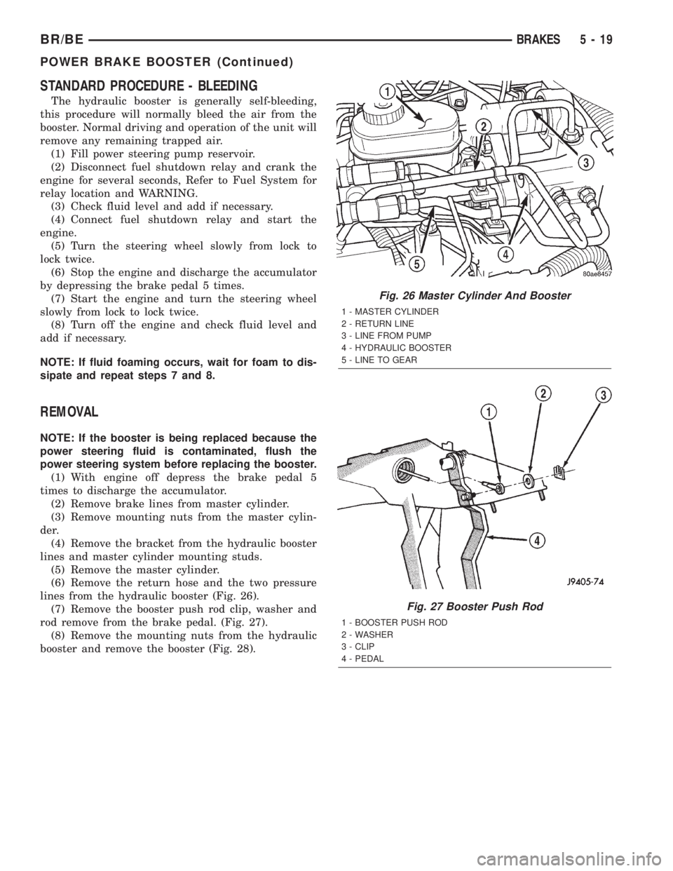
(6) Remove the return hose and the two pressure
lines from the hydraulic booster (Fig. 26).
(7) Remove the booster push rod clip, washer and
rod remove from the brake pedal. (Fig. 27).
(8) Remove the mounting nuts from the hydraulic
booster and remove the booster (Fig. 28).
Fig. 26 Master Cylinder And Booster
1 - MASTER CYLINDER
2 - RETURN LINE
3 - LINE FROM PUMP
4 - HYDRAULIC BOOSTER
5 - LINE TO GEAR
Fig. 27 Booster Push Rod
1 - BOOSTER PUSH ROD
2 - WASHER
3 - CLIP
4 - PEDAL
BR/BEBRAKES 5 - 19
POWER BRAKE BOOSTER (Continued)
Page 301 of 2889
(5) Vacuum should hold steady. If gauge on pump
indicates vacuum loss, check valve is faulty and
should be replaced.
STANDARD PROCEDUREÐMASTER CYLINDER
BLEEDING
A new master cylinder should be bled before instal-
lation on the vehicle. Required bleeding tools include
bleed tubes and a wood dowel to stroke the pistons.
Bleed tubes can be fabricated from brake line.
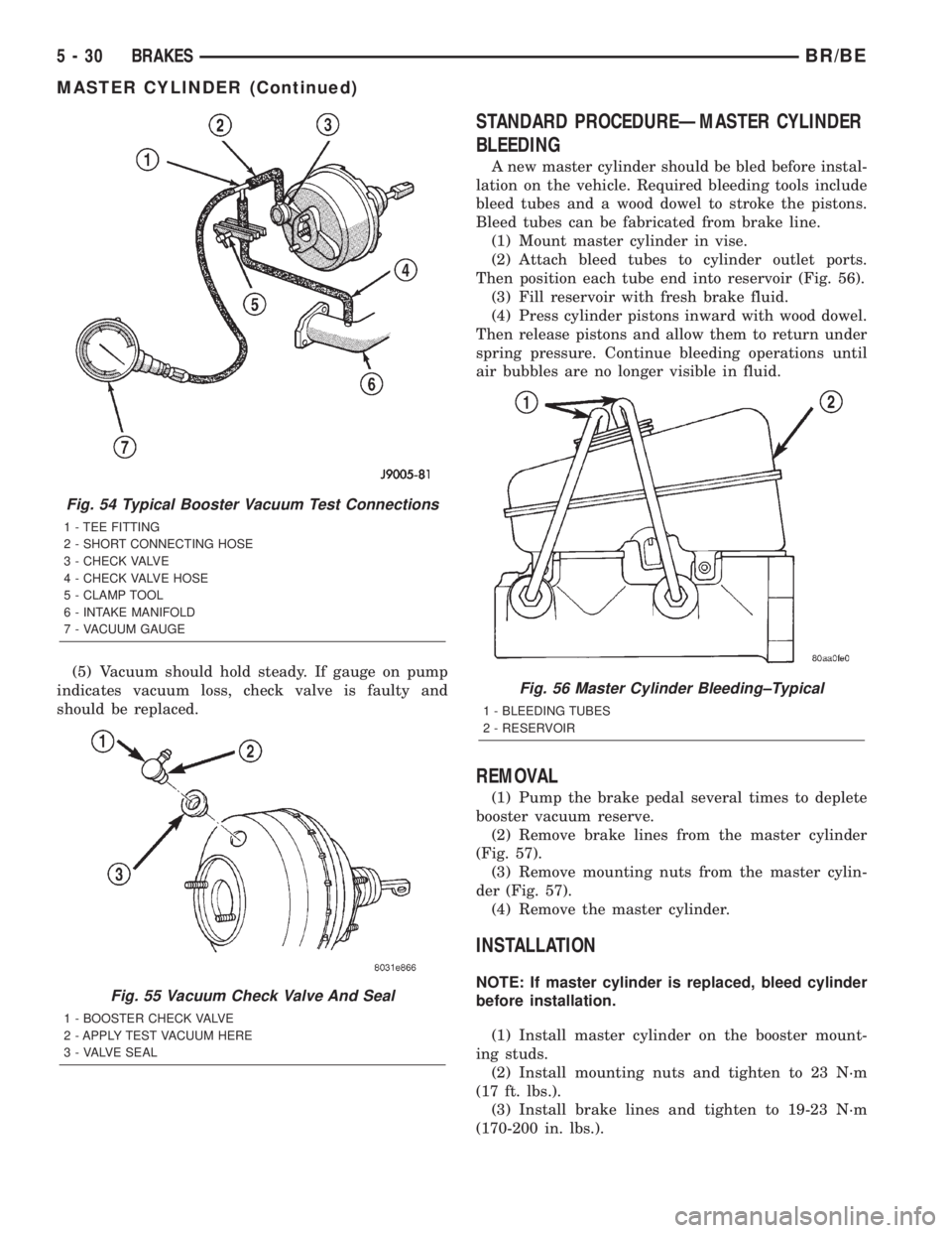
(1) Mount master cylinder in vise.
(2) Attach bleed tubes to cylinder outlet ports.
Then position each tube end into reservoir (Fig. 56).
(3) Fill reservoir with fresh brake fluid.
(4) Press cylinder pistons inward with wood dowel.
Then release pistons and allow them to return under
spring pressure. Continue bleeding operations until
air bubbles are no longer visible in fluid.
REMOVAL
(1) Pump the brake pedal several times to deplete
booster vacuum reserve.
(2) Remove brake lines from the master cylinder
(Fig. 57).
(3) Remove mounting nuts from the master cylin-
der (Fig. 57).
(4) Remove the master cylinder.
INSTALLATION
NOTE: If master cylinder is replaced, bleed cylinder
before installation.
(1) Install master cylinder on the booster mount-
ing studs.
(2) Install mounting nuts and tighten to 23 N´m
(17 ft. lbs.).
(3) Install brake lines and tighten to 19-23 N´m
(170-200 in. lbs.).
Fig. 54 Typical Booster Vacuum Test Connections
1 - TEE FITTING
2 - SHORT CONNECTING HOSE
3 - CHECK VALVE
4 - CHECK VALVE HOSE
5 - CLAMP TOOL
6 - INTAKE MANIFOLD
7 - VACUUM GAUGE
Fig. 55 Vacuum Check Valve And Seal
1 - BOOSTER CHECK VALVE
2 - APPLY TEST VACUUM HERE
3 - VALVE SEAL
Fig. 56 Master Cylinder Bleeding±Typical
1 - BLEEDING TUBES
2 - RESERVOIR
5 - 30 BRAKESBR/BE
MASTER CYLINDER (Continued)
Page 1489 of 2889
FUEL DELIVERY - GASOLINE
DESCRIPTION - FUEL DELIVERY SYSTEM
The fuel delivery system consists of:
²the fuel pump module containing the electric
fuel pump, fuel filter/fuel pressure regulator, rollover
valve (certain modules), fuel gauge sending unit (fuel
level sensor) and a separate fuel filter located at bot-
tom of pump module
²fuel tubes/lines/hoses
²quick-connect fittings
²fuel injector rail
²fuel injectors
²fuel tank
²fuel tank filler/vent tube assembly
²fuel tank filler tube cap
²accelerator pedal
²throttle cable
OPERATION - FUEL DELIVERY SYSTEM
Fuel is returned through the fuel pump module
and back into the fuel tank through the fuel filter/
fuel pressure regulator. A separate fuel return line
from the engine to the tank is not used with any gas-
oline powered engine.
The fuel tank assembly consists of: the fuel tank,
fuel pump module assembly, fuel pump module lock-
nut/gasket and rollover valve(s) (refer to 25, Emis-
sion Control System for rollover valve information).
A fuel filler/vent tube assembly using a pressure/
vacuum, 1/4 turn fuel filler cap is used. The fuel
filler tube contains a flap door located below the fuel
fill cap.
Also to be considered part of the fuel system is the
evaporation control system. This is designed to
reduce the emission of fuel vapors into the atmo-
sphere. The description and function of the Evapora-
tive Control System is found in 25, Emission Control
Systems.
Both fuel filters (at bottom of fuel pump module
and within fuel pressure regulator) are designed for
extended service. They do not require normal sched-
uled maintenance. Filters should only be replaced if
a diagnostic procedure indicates to do so.
DIAGNOSIS AND TESTING - FUEL PRESSURE
LEAK DOWN TEST
Use this test in conjunction with the Fuel Pump
Pressure Test and Fuel Pump Capacity Test.
Check Valve Operation:The electric fuel pump
outlet contains a one-way check valve to prevent fuel
flow back into the tank and to maintain fuel supply
line pressure (engine warm) when pump is not oper-
ational. It is also used to keep the fuel supply line
full of gasoline when pump is not operational. Afterthe vehicle has cooled down, fuel pressure may drop
to 0 psi (cold fluid contracts), but liquid gasoline will
remain in fuel supply line between the check valve
and fuel injectors.Fuel pressure that has
dropped to 0 psi on a cooled down vehicle
(engine off) is a normal condition.When the elec-
tric fuel pump is activated, fuel pressure should
immediately(1±2 seconds) rise to specification.
Abnormally long periods of cranking to restart a
hotengine that has been shut down for a short
period of time may be caused by:
²Fuel pressure bleeding past a fuel injector(s).
²Fuel pressure bleeding past the check valve in
the fuel pump module.
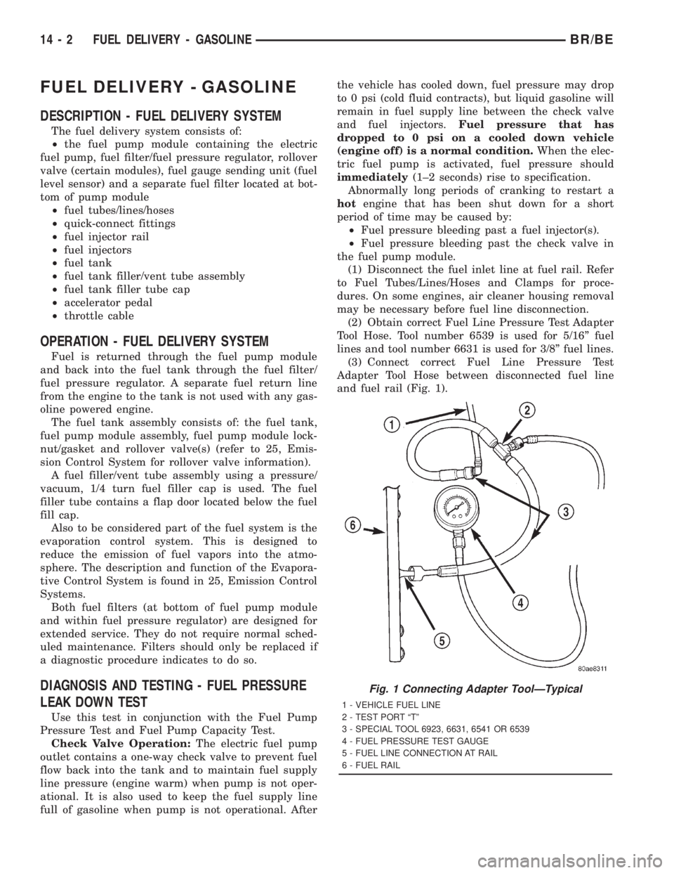
(1) Disconnect the fuel inlet line at fuel rail. Refer
to Fuel Tubes/Lines/Hoses and Clamps for proce-
dures. On some engines, air cleaner housing removal
may be necessary before fuel line disconnection.
(2) Obtain correct Fuel Line Pressure Test Adapter
Tool Hose. Tool number 6539 is used for 5/16º fuel
lines and tool number 6631 is used for 3/8º fuel lines.
(3) Connect correct Fuel Line Pressure Test
Adapter Tool Hose between disconnected fuel line
and fuel rail (Fig. 1).
Fig. 1 Connecting Adapter ToolÐTypical
1 - VEHICLE FUEL LINE
2 - TEST PORT ªTº
3 - SPECIAL TOOL 6923, 6631, 6541 OR 6539
4 - FUEL PRESSURE TEST GAUGE
5 - FUEL LINE CONNECTION AT RAIL
6 - FUEL RAIL
14 - 2 FUEL DELIVERY - GASOLINEBR/BE
Page 1543 of 2889
²Fuel filter/water separator
²Fuel heater
²Fuel heater relay
²Fuel transfer (lift) pump
²Fuel injection pump
²Fuel injectors
²Fuel heater temperature sensor
²Fuel tank
²Fuel tank filler/vent tube assembly
²Fuel tank filler tube cap
²Fuel tank module containing the rollover valve,
fuel gauge sending unit (fuel level sensor) and a sep-
arate fuel filter located at bottom of tank module
²Fuel tubes/lines/hoses
²High-pressure fuel injector lines
²In-tank fuel filter (at bottom of fuel tank mod-
ule)
²Low-pressure fuel supply lines
²Low-pressure fuel return line
²Overflow valve
²Quick-connect fittings
²Throttle cable
²Water draining
OPERATION
WARNING: HIGH-PRESSURE FUEL LINES DELIVER
DIESEL FUEL UNDER EXTREME PRESSURE FROM
THE INJECTION PUMP TO THE FUEL INJECTORS.
THIS MAY BE AS HIGH AS 120,000 KPA (17,405
PSI). USE EXTREME CAUTION WHEN INSPECTING
FOR HIGH-PRESSURE FUEL LEAKS. INSPECT FOR
HIGH-PRESSURE FUEL LEAKS WITH A SHEET OF
CARDBOARD. HIGH FUEL INJECTION PRESSURE
CAN CAUSE PERSONAL INJURY IF CONTACT IS
MADE WITH THE SKIN.
DIAGNOSIS AND TESTING - AIR IN FUEL
SYSTEM
Air will enter the fuel system whenever fuel supply
lines, separator filters, injection pump, high-pressure
lines or injectors are removed or disconnected. Air
trapped in the fuel system can result in hard start-
ing, a rough running engine, engine misfire, low
power, excessive smoke and fuel knock. After service
is performed, air must be bled from the system
before starting the engine.Inspect the fuel system from the fuel transfer
pump to the injectors for loose connections. Leaking
fuel is an indicator of loose connections or defective
seals. Air can also enter the fuel system between the
fuel tank and the transfer pump. Inspect the fuel
tank and fuel lines for damage that might allow air
into the system.
For air bleeding, refer to the Air Bleed Procedure.
DIAGNOSIS AND TESTING - FUEL SUPPLY
RESTRICTIONS
LOW-PRESSURE LINES
Fuel supply line restrictions or a defective fuel
transfer pump can cause starting problems and pre-
vent engine from accelerating. The starting problems
include; low power and/or white fog like exhaust.
Test all fuel supply lines for restrictions or block-
age. Flush or replace as necessary. Bleed fuel system
of air once a fuel supply line has been replaced. Refer
to Air Bleed Procedure for procedures.
To test for fuel line restrictions, a vacuum restric-
tion test may be performed. Refer to Fuel Transfer
Pump Pressure Test.
HIGH-PRESSURE LINES
Restricted (kinked or bent) high-pressure lines can
cause starting problems, poor engine performance,
engine mis-fire and white smoke from exhaust.
Examine all high-pressure lines for any damage.
Each radius on each high-pressure line must be
smooth and free of any bends or kinks.
Replace damaged, restricted or leaking high-pres-
sure fuel lines with correct replacement line.
CAUTION: All high-pressure fuel lines must be
clamped securely in place in holders. Lines cannot
contact each other or other components. Do not
attempt to weld high-pressure fuel lines or to repair
lines that are damaged. If line is kinked or bent, it
must be replaced. Use only recommended lines
when replacement of high-pressure fuel line is nec-
essary.
STANDARD PROCEDURES - WATER DRAINING
AT FUEL FILTER
Refer to Fuel Filter/Water Separator removal/in-
stallation for procedures.
14 - 56 FUEL DELIVERY - DIESELBR/BE
FUEL DELIVERY - DIESEL (Continued)
Page 1544 of 2889
STANDARD PROCEDURES - CLEANING FUEL
SYSTEM PARTS
CAUTION: Cleanliness cannot be overemphasized
when handling or replacing diesel fuel system com-
ponents. This especially includes the fuel injectors,
high-pressure fuel lines and fuel injection pump.
Very tight tolerances are used with these parts. Dirt
contamination could cause rapid part wear and pos-
sible plugging of fuel injector nozzle tip holes. This
in turn could lead to possible engine misfire.
Always wash/clean any fuel system component
thoroughly before disassembly and then air dry.
Cap or cover any open part after disassembly.
Before assembly, examine each part for dirt, grease
or other contaminants and clean if necessary. When
installing new parts, lubricate them with clean
engine oil or clean diesel fuel only.
STANDARD PROCEDURE - AIR BLEED
A certain amount of air becomes trapped in the
fuel system when fuel system components on the
supply and/or high-pressure side are serviced or
replaced. Primary air bleeding is accomplished using
the electric fuel transfer (lift) pump. If the vehicle
has been allowed to run completely out of fuel, the
fuel injectors must also be bled as the fuel injection
pumpis notself-bleeding (priming).
Servicing or replacing components on the fuel
return side will not require air bleeding.
WARNING: DO NOT BLEED AIR FROM THE FUEL
SYSTEM OF A HOT ENGINE.
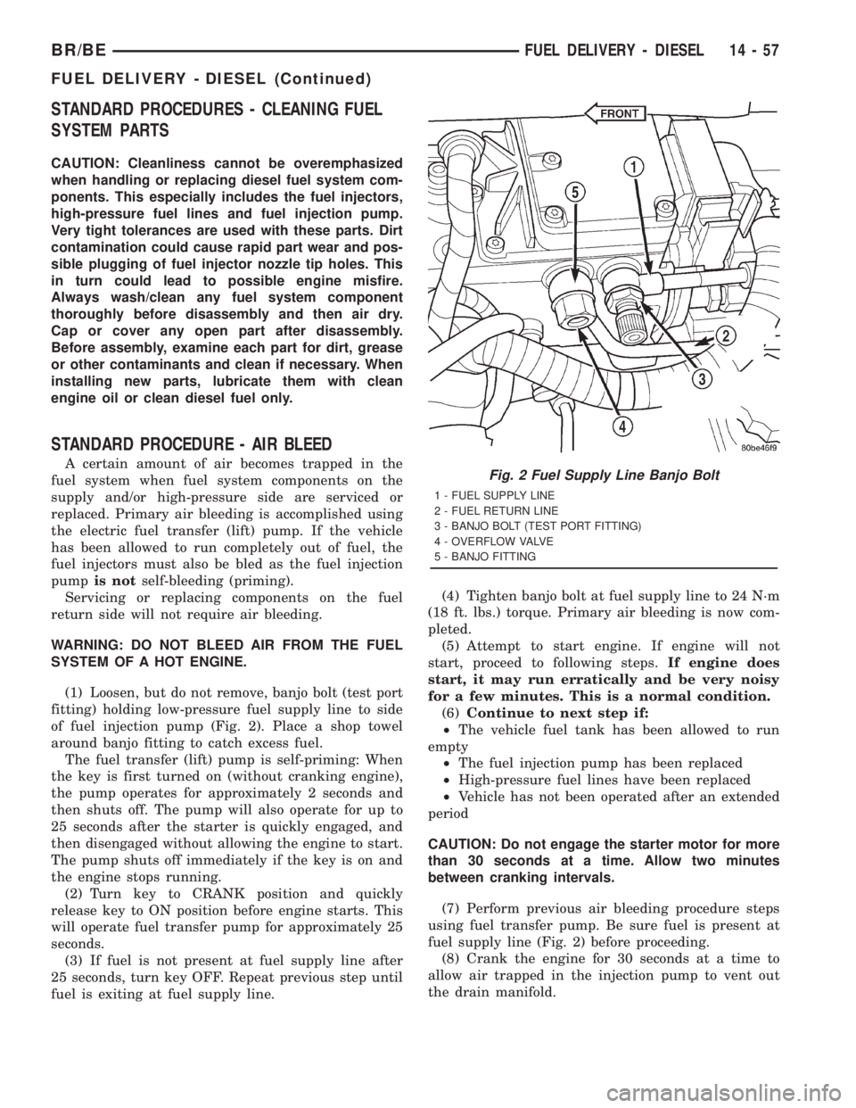
(1) Loosen, but do not remove, banjo bolt (test port
fitting) holding low-pressure fuel supply line to side
of fuel injection pump (Fig. 2). Place a shop towel
around banjo fitting to catch excess fuel.
The fuel transfer (lift) pump is self-priming: When
the key is first turned on (without cranking engine),
the pump operates for approximately 2 seconds and
then shuts off. The pump will also operate for up to
25 seconds after the starter is quickly engaged, and
then disengaged without allowing the engine to start.
The pump shuts off immediately if the key is on and
the engine stops running.
(2) Turn key to CRANK position and quickly
release key to ON position before engine starts. This
will operate fuel transfer pump for approximately 25
seconds.
(3) If fuel is not present at fuel supply line after
25 seconds, turn key OFF. Repeat previous step until
fuel is exiting at fuel supply line.(4) Tighten banjo bolt at fuel supply line to 24 N´m
(18 ft. lbs.) torque. Primary air bleeding is now com-
pleted.
(5) Attempt to start engine. If engine will not
start, proceed to following steps.If engine does
start, it may run erratically and be very noisy
for a few minutes. This is a normal condition.
(6)Continue to next step if:
²The vehicle fuel tank has been allowed to run
empty
²The fuel injection pump has been replaced
²High-pressure fuel lines have been replaced
²Vehicle has not been operated after an extended
period
CAUTION: Do not engage the starter motor for more
than 30 seconds at a time. Allow two minutes
between cranking intervals.
(7) Perform previous air bleeding procedure steps
using fuel transfer pump. Be sure fuel is present at
fuel supply line (Fig. 2) before proceeding.
(8) Crank the engine for 30 seconds at a time to
allow air trapped in the injection pump to vent out
the drain manifold.Fig. 2 Fuel Supply Line Banjo Bolt
1 - FUEL SUPPLY LINE
2 - FUEL RETURN LINE
3 - BANJO BOLT (TEST PORT FITTING)
4 - OVERFLOW VALVE
5 - BANJO FITTING
BR/BEFUEL DELIVERY - DIESEL 14 - 57
FUEL DELIVERY - DIESEL (Continued)
Page 1545 of 2889
WARNING: THE FUEL INJECTION PUMP SUPPLIES
EXTREMELY HIGH FUEL PRESSURE TO EACH INDI-
VIDUAL INJECTOR THROUGH THE HIGH-PRES-
SURE LINES. FUEL UNDER THIS AMOUNT OF
PRESSURE CAN PENETRATE THE SKIN AND
CAUSE PERSONAL INJURY. WEAR SAFETY GOG-
GLES AND ADEQUATE PROTECTIVE CLOTHING
AND AVOID CONTACT WITH FUEL SPRAY WHEN
BLEEDING HIGH-PRESSURE FUEL LINES.
WARNING: ENGINE MAY START WHILE CRANKING
STARTER MOTOR.
Engine may start, may run erratically and be
very noisy for a few minutes. This is a normal
condition.
(9) Thoroughly clean area around injector fittings
where they join injector connector tubes.
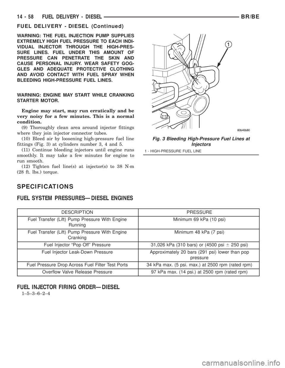
(10) Bleed air by loosening high-pressure fuel line
fittings (Fig. 3) at cylinders number 3, 4 and 5.
(11) Continue bleeding injectors until engine runs
smoothly. It may take a few minutes for engine to
run smooth.
(12) Tighten fuel line(s) at injector(s) to 38 N´m
(28 ft. lbs.) torque.
SPECIFICATIONS
FUEL SYSTEM PRESSURESÐDIESEL ENGINES
DESCRIPTION PRESSURE
Fuel Transfer (Lift) Pump Pressure With Engine
RunningMinimum 69 kPa (10 psi)
Fuel Transfer (Lift) Pump Pressure With Engine
CrankingMinimum 48 kPa (7 psi)
Fuel Injector ªPop Offº Pressure 31,026 kPa (310 bars) or (4500 psi6250 psi)
Fuel Injector Leak-Down Pressure Approximately 20 bars (291 psi) lower than pop
pressure
Fuel Pressure Drop Across Fuel Filter Test Ports 34 kPa max. (5 psi. max.) at 2500 rpm (rated rpm)
Overflow Valve Release Pressure 97 kPa max. (14 psi.) at 2500 rpm (rated rpm)
FUEL INJECTOR FIRING ORDERÐDIESEL
1±5±3±6±2±4
Fig. 3 Bleeding High-Pressure Fuel Lines at
Injectors
1 - HIGH-PRESSURE FUEL LINE
14 - 58 FUEL DELIVERY - DIESELBR/BE
FUEL DELIVERY - DIESEL (Continued)