2001 DODGE RAM ball joints
[x] Cancel search: ball jointsPage 20 of 2889
MAINTENANCE SCHEDULES
LIGHT DUTY ENGINE (1500 AND 2500
MODELS EXCEPT 8.0L) MAINTENANCE
SCHEDULES
There are two maintenance schedules that show
proper service for the vehicle.
First is ScheduleªAº. It lists all the scheduled
maintenance to be performed under ªnormalº operat-
ing conditions.
Second is ScheduleªBºIt is a schedule for vehicles
that are operated under the conditions listed at the
beginning of that schedule.
Use the schedule that best describes the driving
conditions.
Where time and mileage are listed, follow the
interval that occurs first.
At Each Stop For Fuel
²Check engine oil level and add as required.
²Check windshield washer solvent and add as
required.
²Clean windshield and wiper blades as required.
Once A Month
²Check tire pressure and look for unusual wear
or damage.
²Inspect battery and clean and tighten terminals
as required.
²Check fluid levels of coolant reservoir, brake
master cylinder, power steering, and transmission
and add as needed.
²Check all lights and all other electrical items for
correct operation.
²Inspect and clean wiper blades. Replace if
required.
At Each Oil Change
²Inspect exhaust system.
²Inspect brake hoses.
²Adjust rear brake shoe to drum clearance.
²Rotate the tires at each oil change interval
shown on schedule ªAº (7,500 Miles) or every other
interval shown on schedule ªBº (6,000 Miles).
²Check engine coolant level, hoses, and clamps.
²Lubricate steering linkage.
EMISSION CONTROL SYSTEM MAINTENANCE
The scheduled emission maintenance listed inbold
typeon the Maintenance Schedules, must be done at
the mileage specified to assure the continued proper
functioning of the emission control system. These,
and all other maintenance services included in this
manual, should be done to provide the best vehicle
performance and reliability. More frequent mainte-
nance may be needed for vehicles in severe operatingconditions such as dusty areas and very short trip
driving.
FLUID FILL LOCATIONS AND LUBRICATION
POINTS
The fluid check/fill locations and lubrication points
are located in each applicable group.
LIGHT DUTY SCHEDULE ªAº
7,500 Miles (12 000 km) or at 6 months
²Change engine oil.
²Replace engine oil filter.
²Inspect engine coolant level, hoses, and clamps.
²Inspect brake hoses.
²Lubricate the steering linkages.
²Check manual transmission fluid level.
²Inspect exhaust system.
15,000 Miles (24 000 km) or at 12 months
²Change engine oil.
²Replace engine oil filter.
²Inspect engine coolant level, hoses, and clamps.
²Inspect brake hoses.
²Lubricate the steering linkages.
²Check manual transmission fluid level.
²Inspect exhaust system.
22,500 Miles (36 000 km) or at 18 months
²Change engine oil.
²Replace engine oil filter.
²Inspect engine coolant level, hoses, and clamps.
²Inspect brake hoses.
²Inspect brake linings.
²Inspect front wheel bearings. Clean and repack,
if required (4x2).
²Lubricate the steering linkages.
²Lubricate non permanently sealed ball joints.
²Check manual transmission fluid level.
²Inspect exhaust system.
30,000 Miles (48 000 km) or at 24 months
²Replace engine air cleaner element.
²Replace spark plugs.
²Change engine oil.
²Replace engine oil filter.
²Inspect engine coolant level, hoses, and clamps.
²Inspect brake hoses.
²Lubricate the steering linkages.
²Inspect manual transmission fluid level.
²Inspect exhaust system.
37,500 Miles (60 000 km) or at 30 months
²Change engine oil.
²Replace engine oil filter.
²Inspect engine coolant level, hoses, and clamps.
BR/BELUBRICATION & MAINTENANCE 0 - 7
Page 21 of 2889
²Inspect brake hoses.
²Lubricate the steering linkages.
²Inspect manual transmission fluid level.
²Drain and refill transfer case fluid.
²Inspect exhaust system.
45,000 Miles (72 000 km) or at 36 months
²Change engine oil.
²Replace engine oil filter.
²Inspect engine coolant level, hoses, and clamps.
²Inspect brake hoses.
²Inspect brake linings.
²Inspect front wheel bearings. Clean and repack,
if required (4x2).
²Lubricate the steering linkages.
²Lubricate non permanently sealed ball joints.
²Check manual transmission fluid level.
²Inspect exhaust system.
52,500 Miles (84 000 km) or at 42 months
²Change engine oil.
²Replace engine oil filter.
²Inspect engine coolant level, hoses, and clamps.
²Flush and replace engine coolant.
²Inspect brake hoses.
²Lubricate the steering linkages.
²Inspect manual transmission fluid level.
²Inspect exhaust system.
60,000 Miles (96 000 km) or at 48 months
²Replace engine air cleaner element.
²Replace ignition cables.
²Check PCV valve and replace as neces-
sary.*
²Replace spark plugs.
²Inspect auto tension drive belt and replace if
required.
²Change engine oil.
²Replace engine oil filter.
²Inspect engine coolant level, hoses, and clamps.
²Inspect brake hoses.
²Lubricate the steering linkages.
²Check manual transmission fluid level.
²Inspect exhaust system.
67,500 Miles (108 000 km) or at 54 months
²Change engine oil.
²Replace engine oil filter.
²Inspect engine coolant level, hoses, and clamps.
²Inspect brake hoses.
²Inspect brake linings.
²Inspect front wheel bearings. Clean and repack,
if required (4x2).
²Lubricate the steering linkages.
²Lubricate non permanently sealed ball joints.
²Check manual transmission fluid level.
²Inspect exhaust system.
75,000 Miles (120 000 km) or at 60 months
²Inspect auto tension drive belt and replace if
required.**
²Change engine oil.
²Replace engine oil filter.
²Inspect engine coolant level, hoses, and clamps.
²Inspect brake hoses.
²Lubricate the steering linkages.
²Check manual transmission fluid level.
²Drain and refill transfer case fluid.
²Inspect exhaust system.
82,500 Miles (132 000 km) or at 66 months
²Change engine oil.
²Replace engine oil filter.
²Inspect engine coolant level, hoses, and clamps.
²Flush and replace engine coolant if it has been
30,000 miles (48 000 km) or 24 months since last
change.
²Inspect brake hoses.
²Lubricate the steering linkages.
²Inspect manual transmission fluid level.
²Inspect exhaust system.
90,000 Miles (144 000 km) or at 72 months
²Replace engine air cleaner element.
²Check PCV valve and replace as neces-
sary.*
²Replace spark plugs.
²Inspect auto tension drive belt and replace if
required.**
²Change engine oil.
²Replace engine oil filter.
²Inspect engine coolant level, hoses, and clamps.
²Inspect brake hoses.
²Inspect brake linings.
²Inspect front wheel bearings. Clean and repack,
if required (4x2).
²Lubricate the steering linkages.
²Lubricate non permanently sealed ball joints.
²Check manual transmission fluid level.
²Inspect exhaust system.
97,500 Miles (156 000 km) or at 78 months
²Change engine oil.
²Replace engine oil filter.
²Inspect engine coolant level, hoses, and clamps.
²Inspect brake hoses.
²Lubricate the steering linkages.
²Inspect manual transmission fluid level.
²Inspect exhaust system.
100,000 Miles (160,000 km)
²Change automatic transmission fluid, filter and
adjust bands.
0 - 8 LUBRICATION & MAINTENANCEBR/BE
MAINTENANCE SCHEDULES (Continued)
Page 22 of 2889
105,000 Miles (168 000 km) or at 84 months
²Inspect auto tension drive belt and replace if
required.**
²Change engine oil.
²Replace engine oil filter.
²Inspect engine coolant level, hoses, and clamps.
²Inspect brake hoses.
²Lubricate the steering linkages.
²Check manual transmission fluid level.
²Inspect exhaust system.
112,500 Miles (180 000 km) or at 90 months
²Change engine oil.
²Replace engine oil filter.
²Inspect engine coolant level, hoses, and clamps.
²Flush and replace engine coolant if it has been
30,000 miles (48 000 km) or 24 months since last
change.
²Inspect brake hoses.
²Inspect brake linings.
²Inspect front wheel bearings. Clean and repack,
if required (4x2).
²Lubricate the steering linkages.
²Lubricate non permanently sealed ball joints.
²Check manual transmission fluid level.
²Drain and refill transfer case fluid.
²Inspect exhaust system.
120,000 Miles (192 000 km) or at 96 months
²Replace engine air cleaner element.
²Replace ignition cables.
²Check PCV valve and replace as neces-
sary.*
²Replace spark plugs.
²Inspect auto tension drive belt and replace if
required.**
²Change engine oil.
²Replace engine oil filter.
²Inspect engine coolant level, hoses, and clamps.
²Inspect brake hoses.
²Lubricate the steering linkages.
²Check manual transmission fluid level.
²Inspect exhaust system.
*This maintenance is recommended by Daimler-
Chrysler to the customer but it is not required to
maintain warranty on the PCV valve.
**This maintenance is not required if the belt was
previously replaced.
LIGHT DUTY SCHEDULE ªBº
Follow this schedule if the vehicle is usually oper-
ated under one or more of the following conditions.
²Frequent short trips of less than 5 miles.
²Frequent driving in dusty conditions.
²Trailer towing.
²Frequent long periods of engine idling.²More than 50 percent of the driving is at sus-
tained high speeds during hot weather, above 90ÉF
(32ÉC).
²Frequent stop and go driving.
²Day and night temperatures are below freezing.
²Taxi, police or delivery service (commercial ser-
vice).
²Off-road or desert operation.
3,000 Miles (5 000 km)
²Change engine oil.
²Replace engine oil filter.
²Inspect engine coolant level, hoses, and clamps.
²Inspect brake hoses.
²Lubricate the steering linkages.
²Check manual transmission fluid level.
²Inspect exhaust system.
6,000 Miles (10 000 km)
²Change engine oil.
²Replace engine oil filter.
²Inspect engine coolant level, hoses, and clamps.
²Inspect brake hoses.
²Lubricate the steering linkages.
²Check manual transmission fluid level.
²Inspect exhaust system.
9,000 Miles (14 000 km)
²Change engine oil.
²Replace engine oil filter.
²Inspect engine coolant level, hoses, and clamps.
²Inspect brake hoses.
²Lubricate the steering linkages.
²Check manual transmission fluid level.
²Inspect exhaust system.
12,000 Miles (19 000 km)
²Change engine oil.
²Replace engine oil filter.
²Inspect engine coolant level, hoses, and clamps.
²Inspect brake hoses.
²Inspect brake linings.
²Lubricate the steering linkages.
²Check manual transmission fluid level.
²Change rear axle fluid.
²Change front axle fluid (4x4).
²Inspect exhaust system.
15,000 Miles (24 000 km)
²Inspect engine air cleaner element, replace
as necessary.
²Change engine oil.
²Replace engine oil filter.
²Inspect engine coolant level, hoses, and clamps.
²Inspect brake hoses.
²Lubricate the steering linkages.
²Check manual transmission fluid level.
BR/BELUBRICATION & MAINTENANCE 0 - 9
MAINTENANCE SCHEDULES (Continued)
Page 50 of 2889
FRONT - 2WD
TABLE OF CONTENTS
page page
FRONT - 2WD
DESCRIPTION............................7
SPECIFICATIONS.........................8
SPECIAL TOOLS..........................9
HUB / BEARING
REMOVAL...............................9
INSTALLATION............................9
JOUNCE BUMPER
DESCRIPTION............................9
OPERATION.............................9
KNUCKLE
DESCRIPTION............................9
OPERATION.............................10
REMOVAL..............................10
INSTALLATION...........................10
LOWER BALL JOINT
DIAGNOSIS AND TESTING.................10
LOWER BALL JOINT....................10
LOWER CONTROL ARM
REMOVAL..............................10
INSTALLATION...........................10
SHOCK
DESCRIPTION...........................11OPERATION.............................11
DIAGNOSIS AND TESTING.................11
SHOCK...............................11
REMOVAL..............................11
INSTALLATION...........................11
SPRING
DESCRIPTION...........................11
OPERATION.............................11
REMOVAL..............................11
INSTALLATION...........................12
STABILIZER BAR
DESCRIPTION...........................12
OPERATION.............................12
REMOVAL..............................12
INSTALLATION...........................12
UPPER BALL JOINT
DIAGNOSIS AND TESTING.................12
UPPER BALL JOINT.....................12
UPPER CONTROL ARM
REMOVAL..............................13
INSTALLATION...........................13
FRONT - 2WD
DESCRIPTION
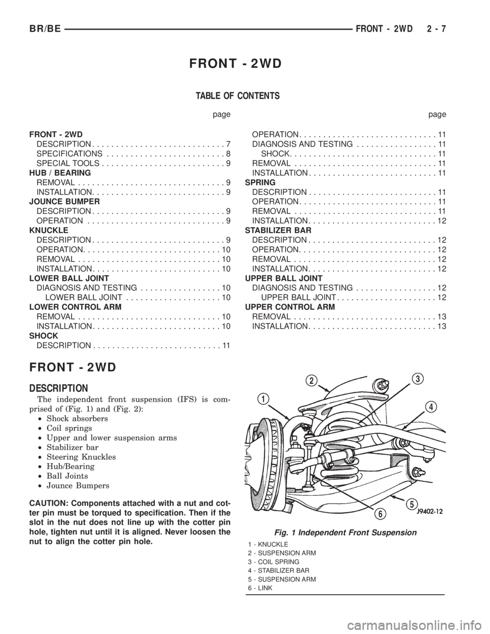
The independent front suspension (IFS) is com-
prised of (Fig. 1) and (Fig. 2):
²Shock absorbers
²Coil springs
²Upper and lower suspension arms
²Stabilizer bar
²Steering Knuckles
²Hub/Bearing
²Ball Joints
²Jounce Bumpers
CAUTION: Components attached with a nut and cot-
ter pin must be torqued to specification. Then if the
slot in the nut does not line up with the cotter pin
hole, tighten nut until it is aligned. Never loosen the
nut to align the cotter pin hole.
Fig. 1 Independent Front Suspension
1 - KNUCKLE
2 - SUSPENSION ARM
3 - COIL SPRING
4 - STABILIZER BAR
5 - SUSPENSION ARM
6 - LINK
BR/BEFRONT - 2WD 2 - 7
Page 52 of 2889
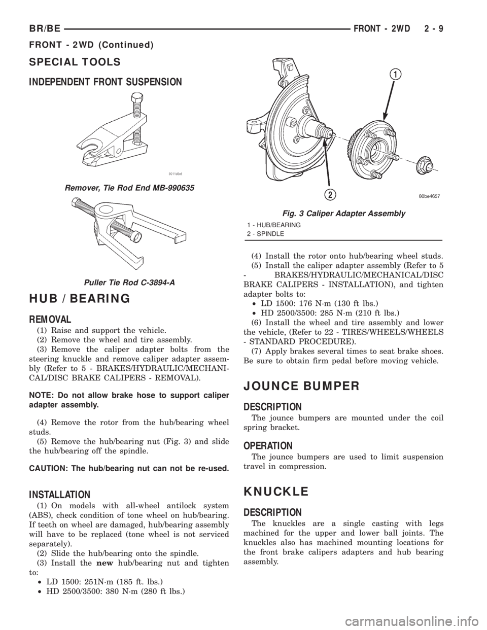
SPECIAL TOOLS
INDEPENDENT FRONT SUSPENSION
HUB / BEARING
REMOVAL
(1) Raise and support the vehicle.
(2) Remove the wheel and tire assembly.
(3) Remove the caliper adapter bolts from the
steering knuckle and remove caliper adapter assem-
bly (Refer to 5 - BRAKES/HYDRAULIC/MECHANI-
CAL/DISC BRAKE CALIPERS - REMOVAL).
NOTE: Do not allow brake hose to support caliper
adapter assembly.
(4) Remove the rotor from the hub/bearing wheel
studs.
(5) Remove the hub/bearing nut (Fig. 3) and slide
the hub/bearing off the spindle.
CAUTION: The hub/bearing nut can not be re-used.
INSTALLATION
(1) On models with all-wheel antilock system
(ABS), check condition of tone wheel on hub/bearing.
If teeth on wheel are damaged, hub/bearing assembly
will have to be replaced (tone wheel is not serviced
separately).
(2) Slide the hub/bearing onto the spindle.
(3) Install thenewhub/bearing nut and tighten
to:
²LD 1500: 251N´m (185 ft. lbs.)
²HD 2500/3500: 380 N´m (280 ft lbs.)(4) Install the rotor onto hub/bearing wheel studs.
(5) Install the caliper adapter assembly (Refer to 5
- BRAKES/HYDRAULIC/MECHANICAL/DISC
BRAKE CALIPERS - INSTALLATION), and tighten
adapter bolts to:
²LD 1500: 176 N´m (130 ft lbs.)
²HD 2500/3500: 285 N´m (210 ft lbs.)
(6) Install the wheel and tire assembly and lower
the vehicle, (Refer to 22 - TIRES/WHEELS/WHEELS
- STANDARD PROCEDURE).
(7) Apply brakes several times to seat brake shoes.
Be sure to obtain firm pedal before moving vehicle.
JOUNCE BUMPER
DESCRIPTION
The jounce bumpers are mounted under the coil
spring bracket.
OPERATION
The jounce bumpers are used to limit suspension
travel in compression.
KNUCKLE
DESCRIPTION
The knuckles are a single casting with legs
machined for the upper and lower ball joints. The
knuckles also has machined mounting locations for
the front brake calipers adapters and hub bearing
assembly.
Remover, Tie Rod End MB-990635
Puller Tie Rod C-3894-A
Fig. 3 Caliper Adapter Assembly
1 - HUB/BEARING
2 - SPINDLE
BR/BEFRONT - 2WD 2 - 9
FRONT - 2WD (Continued)
Page 53 of 2889
OPERATION
The steering knuckles pivots between the upper
and lower ball joints. The steering linkage is
attached to the knuckles controls vehicle steering.
REMOVAL
(1) Raise and support the vehicle.
(2) Remove the wheel and tire assembly.
(3) Remove the brake caliper and rotor, (Refer to 5
- BRAKES/HYDRAULIC/MECHANICAL/DISC
BRAKE CALIPERS - REMOVAL).
(4) Remove the cotter pin and nut from the tie-rod
end. Remove the tie rod end from the knuckle with
Puller C-3894-A.
(5) Remove the cotter pins and nuts from the
upper and lower ball joints. Separate upper ball joint
from knuckle with remover MD-990635. Separate
lower ball joint with remover C-4150A and remove
knuckle.
INSTALLATION
(1) Position the knuckle on the ball joints and
install the ball joint nuts.
(2) Tighten the upper ball joint nut to 81 N´m (60
ft. lbs.) and install cotter pin.
(3) Tighten the lower ball joint nut to:
²LD: 129 N´m (95 ft. lbs.)
²HD: 149 N´m (110 ft. lbs.)
(3) Install the cotter pin.
(4) Install the tie rod end on the steering knuckle
and tighten the nut to 108 N´m (80 ft. lbs.). Install
cotter pin.
(5) Install the brake rotor and caliper, (Refer to 5 -
BRAKES/HYDRAULIC/MECHANICAL/DISC
BRAKE CALIPERS - INSTALLATION).
(6) Install wheel and tire assembly (Refer to 22 -
TIRES/WHEELS/WHEELS - STANDARD PROCE-
DURE).
(7) Remove support and lower vehicle.
LOWER BALL JOINT
DIAGNOSIS AND TESTING - LOWER BALL
JOINT
(1) Raise the front of the vehicle. Place safety floor
stands under both lower suspension arms as far out-
board as possible. Lower the vehicle to allow the
stands to support some or all of the vehicle weight.
NOTE: The upper suspension arms must not be in
maximum rebound position.
(2) Remove the tire and wheel assembly.
(3) Mount a dial indicator solidly under the lower
suspension arm.(4) Position indicator plunger against the bottom
of the steering knuckle lower ball joint boss.
NOTE: The dial Indicator plunger must be perpen-
dicular to the machined surface of the steering
knuckle lower ball joint boss.
(5) Position a pry bar over the top of the upper
suspension arm and under the pivot bar of the upper
suspension arm. Pry down on the upper suspension
arm and then zero the dial indicator.
(6) Reposition the pry bar under the upper suspen-
sion arm and on top of the frame rail. Pry up on the
upper suspension arm and record the dial indicator
reading.
(7) If the travel exceeds 0.8 mm (0.030 in.) replace
the suspension arm.
LOWER CONTROL ARM
REMOVAL
(1) Raise and support the vehicle.
(2) Remove the tire and wheel assembly.
(3) Remove the brake caliper assembly and rotor,
(Refer to 5 - BRAKES/HYDRAULIC/MECHANICAL/
ROTORS - REMOVAL).
(4) Remove the cotter pin and nut from the tie rod.
Remove the tie rod end from the steering knuckle
with Puller C-3894-A.
(5) Remove the stabilizer bar link from lower sus-
pension arm.
(6) Support the lower suspension arm outboard
end with jack. Place a jack under the arm in the
front of the shock mount.
(7) Remove the cotter pin and nut from the lower
ball joint. Separate the ball joint with Remover
C-4150A.
(8) Remove the lower shock bolt from the suspen-
sion arm.
(9) Lower the jack and suspension arm until
spring tension is relieved. Remove spring and rubber
isolator (Fig. 5).
(10) Remove bolts mounting suspension arm to
crossmember and remove arm.
INSTALLATION
(1) Position the suspension arm on the crossmem-
ber and install the bolts and nuts snug.
(2) Install the rubber isolator on top of the spring.
Position the spring into upper spring seat.
(3) Raise the lower suspension arm with a jack
and position the spring into the lower suspension
arm mount.
(4) Install the lower shock bolt and tighten to 142
N´m (105 ft. lbs.).
2 - 10 FRONT - 2WDBR/BE
KNUCKLE (Continued)
Page 57 of 2889
FRONT - 4WD
TABLE OF CONTENTS
page page
FRONT - 4WD
DESCRIPTION...........................14
SPECIFICATIONS........................15
SPECIAL TOOLS.........................16
HUB / BEARING
REMOVAL..............................16
INSTALLATION...........................18
KNUCKLE
DESCRIPTION...........................20
OPERATION.............................20
REMOVAL..............................20
INSTALLATION...........................20
LOWER CONTROL ARM
REMOVAL..............................20
INSTALLATION...........................20
SHOCK
DESCRIPTION...........................21
OPERATION.............................21
DIAGNOSIS AND TESTING.................21
SHOCK..............................21
REMOVAL..............................21
INSTALLATION...........................21
SPRING
DESCRIPTION...........................22OPERATION.............................22
REMOVAL..............................22
INSTALLATION...........................22
STABILIZER BAR
DESCRIPTION...........................22
OPERATION.............................22
REMOVAL..............................22
INSTALLATION...........................23
TRACK BAR
DESCRIPTION...........................23
OPERATION.............................23
DIAGNOSIS AND TESTING.................23
TRACK BAR...........................23
REMOVAL..............................23
INSTALLATION...........................23
UPPER CONTROL ARM
REMOVAL..............................23
INSTALLATION...........................24
LOWER BALL JOINT
REMOVAL..............................24
INSTALLATION...........................25
UPPER BALL JOINT
REMOVAL..............................25
INSTALLATION...........................25
FRONT - 4WD
DESCRIPTION
The link/coil suspension allows each wheel to adapt
to different road surfaces. The suspension is com-
prised of (Fig. 1) :
²Shock absorbers
²Coil springs
²Upper and lower suspension arms
²Stabilizer bar
²Track bar
²Steering Knuckles
²Hub/Bearing
²Ball Joints
²Jounce Bumpers
CAUTION: Components attached with a nut and cot-
ter pin must be torqued to specification. Then if the
slot in the nut does not line up with the cotter pin
hole, tighten nut until it is aligned. Never loosen the
nut to align the cotter pin hole.CAUTION: Suspension components with rubber
bushings (except stabilizer bar) should be tightened
with the vehicle at normal height. It is important to
have the springs supporting the weight of the vehi-
cle when the fasteners are torqued. If springs are
not at their normal ride position, vehicle ride com-
fort could be affected and premature bushing wear
may occur.
DESCRIPTION
The upper and lower suspension arms use bush-
ings to isolate road noise. The suspension arms are
bolted to the frame and axle through the rubber
bushings. The lower suspension arm uses cam bolts
at the axle to allow for caster and pinion angle
adjustment.
2 - 14 FRONT - 4WDBR/BE
Page 63 of 2889

(8) Install a new cotter pin in hub nut. Tighten the
nut as needed to align cotter pin hole in shaft with
the opening in the nut.
(9) Install the rotor, brake caliper with adapter,
(Refer to 5 - BRAKES/HYDRAULIC/MECHANICAL/
DISC BRAKE CALIPERS - INSTALLATION).
(10) Install the ABS wheel speed sensor if
equipped, (Refer to 5 - BRAKES/ELECTRICAL/
FRONT WHEEL SPEED SENSOR - INSTALLA-
TION).
(11) Install the wheel and tire assemblies, (Refer
to 22 - TIRES/WHEELS/WHEELS - STANDARD
PROCEDURE).
(12) Remove the support and lower the vehicle.
(13) Apply the brakes several times to seat the
brake shoes and the caliper piston. Do not move the
vehicle until a firm brake pedal is obtained.
KNUCKLE
DESCRIPTION
The knuckles are a single casting with legs
machined for the upper and lower ball joints. The
knuckles also has machined mounting locations for
the front brake calipers adapters and hub bearing
assembly.
OPERATION
The steering knuckles pivots between the upper
and lower ball joints. The steering linkage is
attached to the knuckles controls vehicle steering.
REMOVAL
(1) Remove hub bearing and axle shaft.
(2) Remove tie-rod or drag link end from the steer-
ing knuckle arm.
(3) Remove the ABS sensor wire and bracket from
knuckle.
(4) Remove the cotter pin from the upper ball stud
nut. Remove the upper and lower ball stud nuts.
(5) Strike the steering knuckle with a brass ham-
mer to loosen. Remove knuckle from axle tube yokes.
REMOVAL
(1) Remove hub bearing and axle shaft.
(2) Remove tie-rod or drag link end from the steer-
ing knuckle arm.
(3) Remove the ABS sensor wire and bracket from
knuckle. Refer to Brakes, for proper procedures.
(4) Remove the cotter pin from the upper ball stud
nut. Remove the upper and lower ball stud nuts.
(5) Strike the steering knuckle with a brass ham-
mer to loosen.
(6) Remove knuckle from axle tube yokes.
INSTALLATION
(1) Position the steering knuckle on the ball studs.
(2) Install and tighten lower ball stud nut to 108
N´m (80 ft. lbs.) torque. Advance nut to next slot to
line up hole and install new cotter pin.
(3) Install and tighten upper ball stud nut to 101
N´m (75 ft. lbs.) torque. Advance nut to next slot to
line up hole and install new cotter pin.
(4) Install the hub bearing and axle shaft.
(5) Install tie-rod or drag link end onto the steer-
ing knuckle arm.
(6) Install the ABS sensor wire and bracket to the
knuckle. Refer to Brakes, for proper procedures.
INSTALLATION
(1) Position the steering knuckle on the ball studs.
(2) Install and tighten lower ball stud nut to 47
N´m (35 ft. lbs.) torque. Do not install cotter pin at
this time.
(3) Install and tighten upper ball stud nut to 94
N´m (70 ft. lbs.) torque. Advance nut to next slot to
line up hole and install new cotter pin.
(4) Retorque lower ball stud nut to 190±217 N´m
(140±160 ft. lbs.) torque. Advance nut to next slot to
line up hole and install new cotter pin.
(5) Install the hub bearing and axle shaft.
(6) Install tie-rod or drag link end onto the steer-
ing knuckle arm.
(7) Install the ABS sensor wire and bracket to the
knuckle. Refer to Brakes, for proper procedure.
LOWER CONTROL ARM
REMOVAL
(1) Raise and support the vehicle.
(2) Paint or scribe alignment marks on the cam
adjusters and suspension arm for installation refer-
ence (Fig. 15).
(3) Remove the lower suspension arm nut, cam
and cam bolt from the axle.
(4) Remove the nut and bolt from the frame rail
bracket and remove the lower suspension arm (Fig.
22).
INSTALLATION
(1) Position the lower suspension arm at the axle
bracket and frame rail bracket.
(2) Install the rear bolt and finger tighten the nut.
(3) Install the cam bolt, cam and nut in the axle
and align the reference marks.
(4) Remove support and lower the vehicle.
(5) Tighten cam nut at the axle bracket to 190
N´m (140 ft. lbs.). Tighten rear nut at the frame
bracket to 190 N´m (140 ft. lbs.).
2 - 20 FRONT - 4WDBR/BE
HUB / BEARING (Continued)