2001 DODGE RAM compression ratio
[x] Cancel search: compression ratioPage 52 of 2889
SPECIAL TOOLS
INDEPENDENT FRONT SUSPENSION
HUB / BEARING
REMOVAL
(1) Raise and support the vehicle.
(2) Remove the wheel and tire assembly.
(3) Remove the caliper adapter bolts from the
steering knuckle and remove caliper adapter assem-
bly (Refer to 5 - BRAKES/HYDRAULIC/MECHANI-
CAL/DISC BRAKE CALIPERS - REMOVAL).
NOTE: Do not allow brake hose to support caliper
adapter assembly.
(4) Remove the rotor from the hub/bearing wheel
studs.
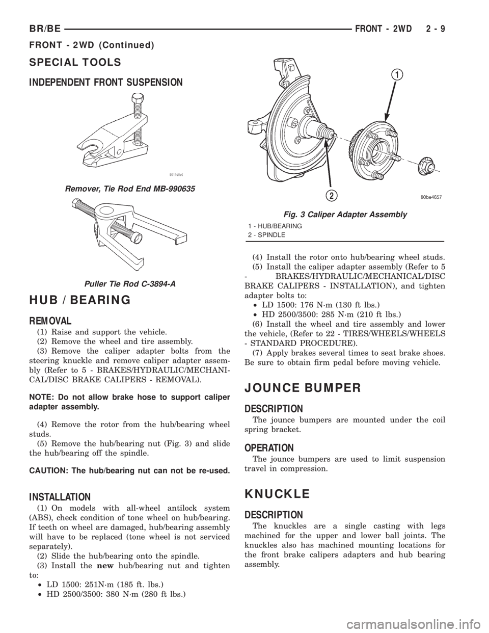
(5) Remove the hub/bearing nut (Fig. 3) and slide
the hub/bearing off the spindle.
CAUTION: The hub/bearing nut can not be re-used.
INSTALLATION
(1) On models with all-wheel antilock system
(ABS), check condition of tone wheel on hub/bearing.
If teeth on wheel are damaged, hub/bearing assembly
will have to be replaced (tone wheel is not serviced
separately).
(2) Slide the hub/bearing onto the spindle.
(3) Install thenewhub/bearing nut and tighten
to:
²LD 1500: 251N´m (185 ft. lbs.)
²HD 2500/3500: 380 N´m (280 ft lbs.)(4) Install the rotor onto hub/bearing wheel studs.
(5) Install the caliper adapter assembly (Refer to 5
- BRAKES/HYDRAULIC/MECHANICAL/DISC
BRAKE CALIPERS - INSTALLATION), and tighten
adapter bolts to:
²LD 1500: 176 N´m (130 ft lbs.)
²HD 2500/3500: 285 N´m (210 ft lbs.)
(6) Install the wheel and tire assembly and lower
the vehicle, (Refer to 22 - TIRES/WHEELS/WHEELS
- STANDARD PROCEDURE).
(7) Apply brakes several times to seat brake shoes.
Be sure to obtain firm pedal before moving vehicle.
JOUNCE BUMPER
DESCRIPTION
The jounce bumpers are mounted under the coil
spring bracket.
OPERATION
The jounce bumpers are used to limit suspension
travel in compression.
KNUCKLE
DESCRIPTION
The knuckles are a single casting with legs
machined for the upper and lower ball joints. The
knuckles also has machined mounting locations for
the front brake calipers adapters and hub bearing
assembly.
Remover, Tie Rod End MB-990635
Puller Tie Rod C-3894-A
Fig. 3 Caliper Adapter Assembly
1 - HUB/BEARING
2 - SPINDLE
BR/BEFRONT - 2WD 2 - 9
FRONT - 2WD (Continued)
Page 548 of 2889

OPERATION
The camshaft position sensor provides fuel injec-
tion synchronization and cylinder identification.
The distributor does not have built in centrifugal
or vacuum assisted advance. Base ignition timing
and all timing advance is controlled by the Power-
train Control Module (PCM). Because ignition timing
is controlled by the PCM,base ignition timing is
not adjustable.
The distributor is held to the engine in the conven-
tional method using a holddown clamp and bolt.
Although the distributor can be rotated, it will
have no effect on ignition timing.
All distributors contain an internal oil seal that
prevents oil from entering the distributor housing.
The seal is not serviceable.
REMOVAL
CAUTION: Base ignition timing is not adjustable on
any engine. Distributors do not have built in centrif-
ugal or vacuum assisted advance. Base ignition
timing and timing advance are controlled by the
Powertrain Control Module (PCM). Because a con-
ventional timing light can not be used to adjust dis-
tributor position after installation, note position of
distributor before removal.
(1) Remove air cleaner assembly.
(2) Disconnect negative cable from battery.
(3) Remove distributor cap from distributor (two
screws).
(4) Mark the position of distributor housing in
relationship to engine or dash panel. This is done to
aid in installation.(5) Before distributor is removed, the number one
cylinder must be brought to the Top Dead Center
(TDC) firing position.
(6) Attach a socket to the Crankshaft Vibration
Damper mounting bolt.
(7) Slowly rotate engine clockwise, as viewed from
front, until indicating mark on crankshaft vibration
damper is aligned to 0 degree (TDC) mark on timing
chain cover (Fig. 18).
(8) The distributor rotor should now be aligned to
the CYL. NO. 1 alignment mark (stamped) into the
camshaft position sensor (Fig. 19). If not, rotate the
crankshaft through another complete 360 degree
turn. Note the position of the number one cylinder
spark plug cable (on the cap) in relation to rotor.
Rotor should now be aligned to this position.
(9) Disconnect camshaft position sensor wiring
harness from main engine wiring harness.
(10) Remove distributor rotor from distributor
shaft.
(11) Remove distributor holddown clamp bolt and
clamp (Fig. 20). Remove distributor from vehicle.
CAUTION: Do not crank engine with distributor
removed. Distributor/crankshaft relationship will be
lost.
INSTALLATION
If engine has been cranked while distributor is
removed, establish the relationship between distribu-
tor shaft and number one piston position as follows:
Rotate crankshaft in a clockwise direction, as
viewed from front, until number one cylinder piston
is at top of compression stroke (compression should
be felt on finger with number one spark plug
Fig. 17 Distributor and Camshaft Position Sensor
1 - SYNC SIGNAL GENERATOR
2 - CAMSHAFT POSITION SENSOR
3 - PULSE RING
4 - DISTRIBUTOR ASSEMBLY
Fig. 18 Damper-To-Cover Alignment MarksÐTypical
1 - ALIGNMENT MARK
2 - TIMING CHAIN COVER MARKS
3 - CRANKSHAFT VIBRATION DAMPER
BR/BEIGNITION CONTROL 8I - 11
DISTRIBUTOR (Continued)
Page 551 of 2889

filled coils. The rear coil pack contains two indepen-
dent epoxy filled coils.
OPERATION - 3.9L/5.2L/5.9L
The Powertrain Control Module (PCM) opens and
closes the ignition coil ground circuit for ignition coil
operation.
Battery voltage is supplied to the ignition coil pos-
itive terminal from the ASD relay. If the PCM does
not see a signal from the crankshaft and camshaft
sensors (indicating the ignition key is ON but the
engine is not running), it will shut down the ASD cir-
cuit.
Base ignition timing is not adjustable on any
engine.By controlling the coil ground circuit, the
PCM is able to set the base timing and adjust the
ignition timing advance. This is done to meet chang-
ing engine operating conditions.
OPERATION - 8.0L
When one of the 5 independent coils discharges, it
fires two paired cylinders at the same time (one cyl-
inder on compression stroke and the other cylinder
on exhaust stroke).
Coil firing is paired together on cylinders:
²Number 5 and 10
²Number 9 and 8
²Number 1 and 6
²Number 7 and 4
²Number 3 and 2
The ignition system is controlled by the Powertrain
Control Module (PCM) on all engines.
Battery voltage is supplied to all of the ignition
coils positive terminals from the ASD relay. If the
PCM does not see a signal from the crankshaft and
camshaft sensors (indicating the ignition key is ONbut the engine is not running), it will shut down the
ASD circuit.
Base ignition timing is not adjustable on the
8.0L V-10 engine.By controlling the coil ground cir-
cuit, the PCM is able to set the base timing and
adjust the ignition timing advance. This is done to
meet changing engine operating conditions.
The PCM adjusts ignition timing based on inputs it
receives from:
²The engine coolant temperature sensor
²The crankshaft position sensor (engine speed)
²The manifold absolute pressure (MAP) sensor
²The throttle position sensor
²Transmission gear selection
REMOVAL - 3.9L/5.2L/5.9L
The ignition coil is an epoxy filled type. If the coil
is replaced, it must be replaced with the same type.
3.9L V-6 or 5.2/5.9L V-8 LDC-Gas Engines: The coil
is mounted to a bracket that is bolted to the front of
the right engine cylinder head (Fig. 25). This bracket
is mounted on top of the automatic belt tensioner
bracket using common bolts.
5.9L V-8 HDC-Gas Engine: The coil is mounted to
a bracket that is bolted to the air injection pump
(AIR pump) mounting bracket (Fig. 26).
(1) Disconnect the primary wiring from the igni-
tion coil.
(2) Disconnect the secondary spark plug cable from
the ignition coil.
Fig. 24 Ignition Coil PacksÐ8.0L V-10 Engine
Fig. 25 Ignition CoilÐ3.9L V-6 or 5.2/5.9L V-8
LDC-Gas Engines
1 - ACCESSORY DRIVE BELT TENSIONER
2 - COIL CONNECTOR
3 - IGNITION COIL
4 - COIL MOUNTING BOLTS
8I - 14 IGNITION CONTROLBR/BE
IGNITION COIL (Continued)
Page 1148 of 2889
ENGINE
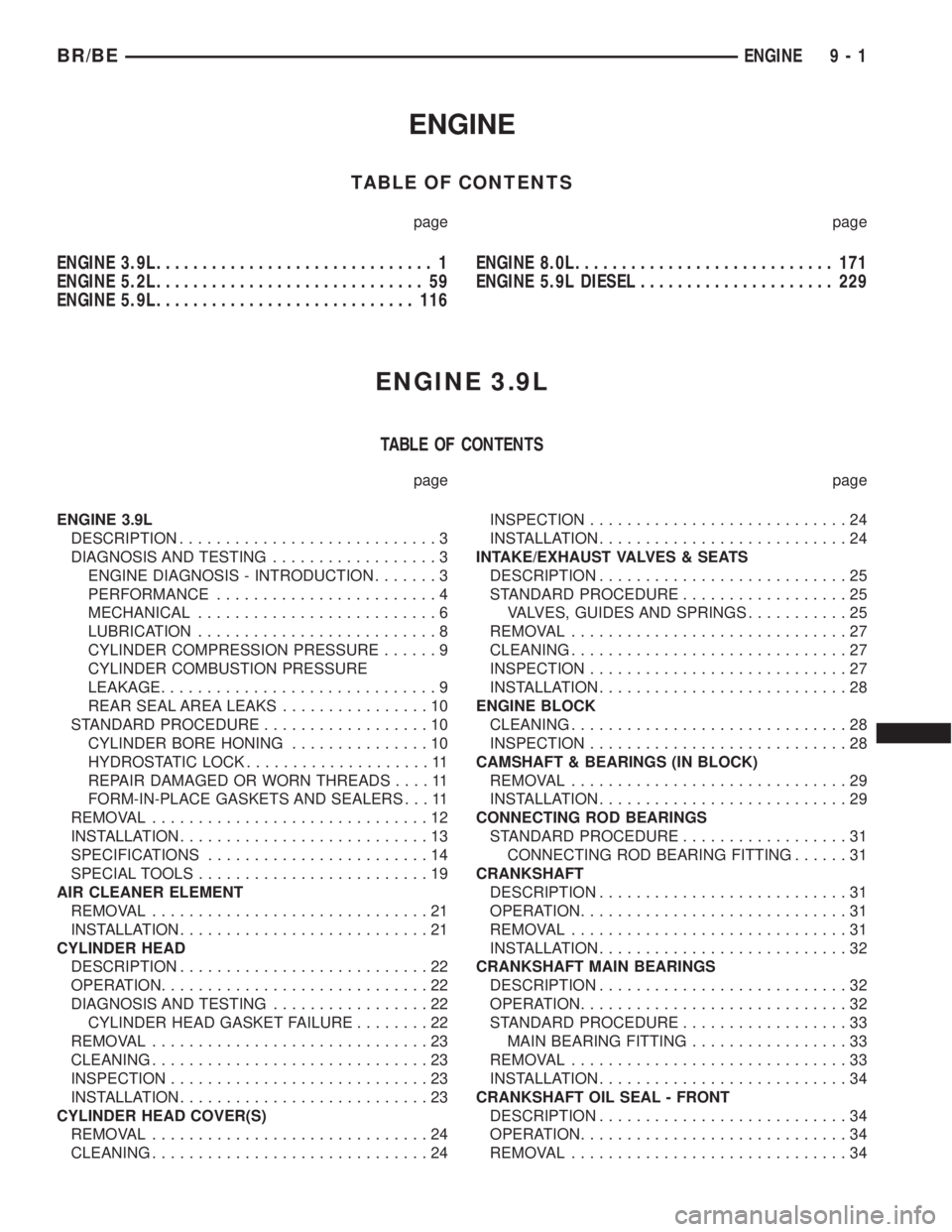
TABLE OF CONTENTS
page page
ENGINE 3.9L.............................. 1
ENGINE 5.2L............................. 59
ENGINE 5.9L............................ 116ENGINE 8.0L............................ 171
ENGINE 5.9L DIESEL..................... 229
ENGINE 3.9L
TABLE OF CONTENTS
page page
ENGINE 3.9L
DESCRIPTION............................3
DIAGNOSIS AND TESTING..................3
ENGINE DIAGNOSIS - INTRODUCTION.......3
PERFORMANCE........................4
MECHANICAL..........................6
LUBRICATION..........................8
CYLINDER COMPRESSION PRESSURE......9
CYLINDER COMBUSTION PRESSURE
LEAKAGE..............................9
REAR SEAL AREA LEAKS................10
STANDARD PROCEDURE..................10
CYLINDER BORE HONING...............10
HYDROSTATIC LOCK....................11
REPAIR DAMAGED OR WORN THREADS....11
FORM-IN-PLACE GASKETS AND SEALERS . . . 11
REMOVAL..............................12
INSTALLATION...........................13
SPECIFICATIONS........................14
SPECIAL TOOLS.........................19
AIR CLEANER ELEMENT
REMOVAL..............................21
INSTALLATION...........................21
CYLINDER HEAD
DESCRIPTION...........................22
OPERATION.............................22
DIAGNOSIS AND TESTING.................22
CYLINDER HEAD GASKET FAILURE........22
REMOVAL..............................23
CLEANING..............................23
INSPECTION............................23
INSTALLATION...........................23
CYLINDER HEAD COVER(S)
REMOVAL..............................24
CLEANING..............................24INSPECTION............................24
INSTALLATION...........................24
INTAKE/EXHAUST VALVES & SEATS
DESCRIPTION...........................25
STANDARD PROCEDURE..................25
VALVES, GUIDES AND SPRINGS...........25
REMOVAL..............................27
CLEANING..............................27
INSPECTION............................27
INSTALLATION...........................28
ENGINE BLOCK
CLEANING..............................28
INSPECTION............................28
CAMSHAFT & BEARINGS (IN BLOCK)
REMOVAL..............................29
INSTALLATION...........................29
CONNECTING ROD BEARINGS
STANDARD PROCEDURE..................31
CONNECTING ROD BEARING FITTING......31
CRANKSHAFT
DESCRIPTION...........................31
OPERATION.............................31
REMOVAL..............................31
INSTALLATION...........................32
CRANKSHAFT MAIN BEARINGS
DESCRIPTION...........................32
OPERATION.............................32
STANDARD PROCEDURE..................33
MAIN BEARING FITTING.................33
REMOVAL..............................33
INSTALLATION...........................34
CRANKSHAFT OIL SEAL - FRONT
DESCRIPTION...........................34
OPERATION.............................34
REMOVAL..............................34
BR/BEENGINE 9 - 1
Page 1161 of 2889
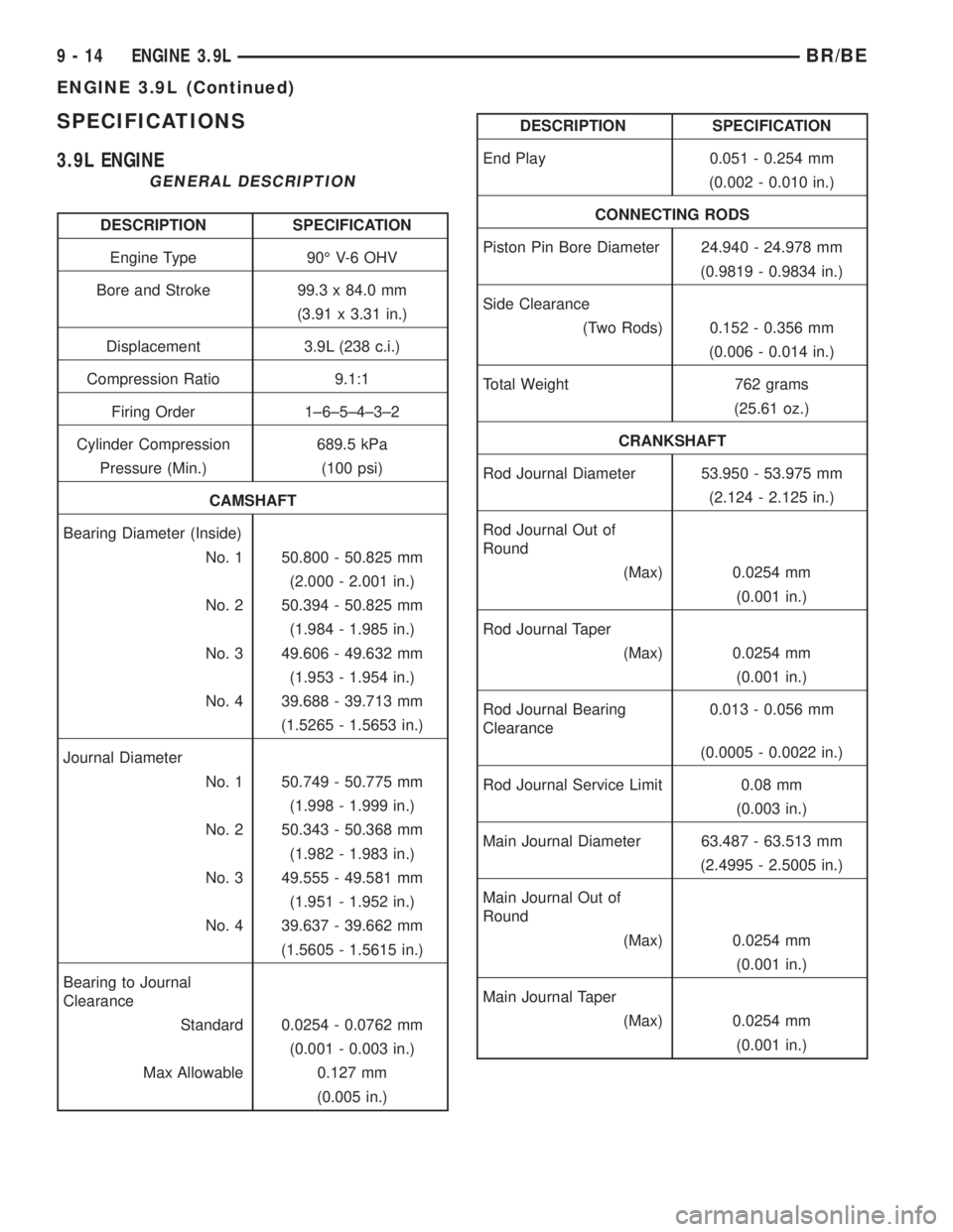
SPECIFICATIONS
3.9L ENGINE
GENERAL DESCRIPTION
DESCRIPTION SPECIFICATION
Engine Type 90É V-6 OHV
Bore and Stroke 99.3 x 84.0 mm
(3.91 x 3.31 in.)
Displacement 3.9L (238 c.i.)
Compression Ratio 9.1:1
Firing Order 1±6±5±4±3±2
Cylinder Compression 689.5 kPa
Pressure (Min.) (100 psi)
CAMSHAFT
Bearing Diameter (Inside)
No. 1 50.800 - 50.825 mm
(2.000 - 2.001 in.)
No. 2 50.394 - 50.825 mm
(1.984 - 1.985 in.)
No. 3 49.606 - 49.632 mm
(1.953 - 1.954 in.)
No. 4 39.688 - 39.713 mm
(1.5265 - 1.5653 in.)
Journal Diameter
No. 1 50.749 - 50.775 mm
(1.998 - 1.999 in.)
No. 2 50.343 - 50.368 mm
(1.982 - 1.983 in.)
No. 3 49.555 - 49.581 mm
(1.951 - 1.952 in.)
No. 4 39.637 - 39.662 mm
(1.5605 - 1.5615 in.)
Bearing to Journal
Clearance
Standard 0.0254 - 0.0762 mm
(0.001 - 0.003 in.)
Max Allowable 0.127 mm
(0.005 in.)
DESCRIPTION SPECIFICATION
End Play 0.051 - 0.254 mm
(0.002 - 0.010 in.)
CONNECTING RODS
Piston Pin Bore Diameter 24.940 - 24.978 mm
(0.9819 - 0.9834 in.)
Side Clearance
(Two Rods) 0.152 - 0.356 mm
(0.006 - 0.014 in.)
Total Weight 762 grams
(25.61 oz.)
CRANKSHAFT
Rod Journal Diameter 53.950 - 53.975 mm
(2.124 - 2.125 in.)
Rod Journal Out of
Round
(Max) 0.0254 mm
(0.001 in.)
Rod Journal Taper
(Max) 0.0254 mm
(0.001 in.)
Rod Journal Bearing
Clearance0.013 - 0.056 mm
(0.0005 - 0.0022 in.)
Rod Journal Service Limit 0.08 mm
(0.003 in.)
Main Journal Diameter 63.487 - 63.513 mm
(2.4995 - 2.5005 in.)
Main Journal Out of
Round
(Max) 0.0254 mm
(0.001 in.)
Main Journal Taper
(Max) 0.0254 mm
(0.001 in.)
9 - 14 ENGINE 3.9LBR/BE
ENGINE 3.9L (Continued)
Page 1164 of 2889
DESCRIPTION SPECIFICATION
End Play None
Length 75.946 - 76.454 mm
(2.990 - 3.010 in.)
PISTON RINGS
Ring Gap
Compression Rings 0.254 - 0.508 mm
(0.010 - 0.020 in.)
Oil Control (Steel Rails) 0.254 - 1.270 mm
(0.010 - 0.050 in.)
Ring Side Clearance
Compression Rings 0.038 - 0.076 mm
(0.0015 - 0.0030 in.)
Oil Control (Steel Rails) 0.06 - 0.21 mm
(0.002 - 0.008 in.)
Ring Width
Compression Rings 1.971 - 1.989 mm
(0.0776 - 0.0783 in.)
Oil Control (Steel Rails) 3.848 - 3.975 mm
(0.1515 - 0.1565 in.)
VALVE TIMING
Exhaust Valve
Closes 16É (ATDC)
Opens 52É (BBDC)
Duration 248É
Intake Valve
Closes 50É (ABDC)
Opens 10É (BTDC)
Duration 240É
Valve Overlap 26ÉOVERSIZE AND UNDERSIZE ENGINE
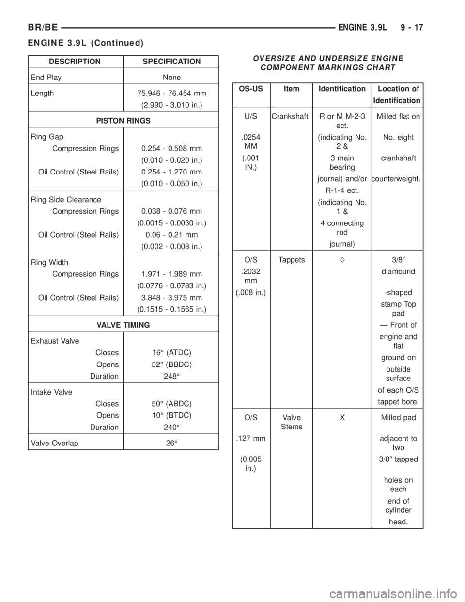
COMPONENT MARKINGS CHART
OS-US Item Identification Location of
Identification
U/S Crankshaft R or M M-2-3
ect.Milled flat on
.0254
MM(indicating No.
2&No. eight
(.001
IN.)3 main
bearingcrankshaft
journal) and/or counterweight.
R-1-4 ect.
(indicating No.
1&
4 connecting
rod
journal)
O/S TappetsL3/89
.2032
mmdiamound
(.008 in.) -shaped
stamp Top
pad
Ð Front of
engine and
flat
ground on
outside
surface
of each O/S
tappet bore.
O/S Valve
StemsX Milled pad
.127 mm adjacent to
two
(0.005
in.)3/89tapped
holes on
each
end of
cylinder
head.
BR/BEENGINE 3.9L 9 - 17
ENGINE 3.9L (Continued)
Page 1169 of 2889
CYLINDER HEAD
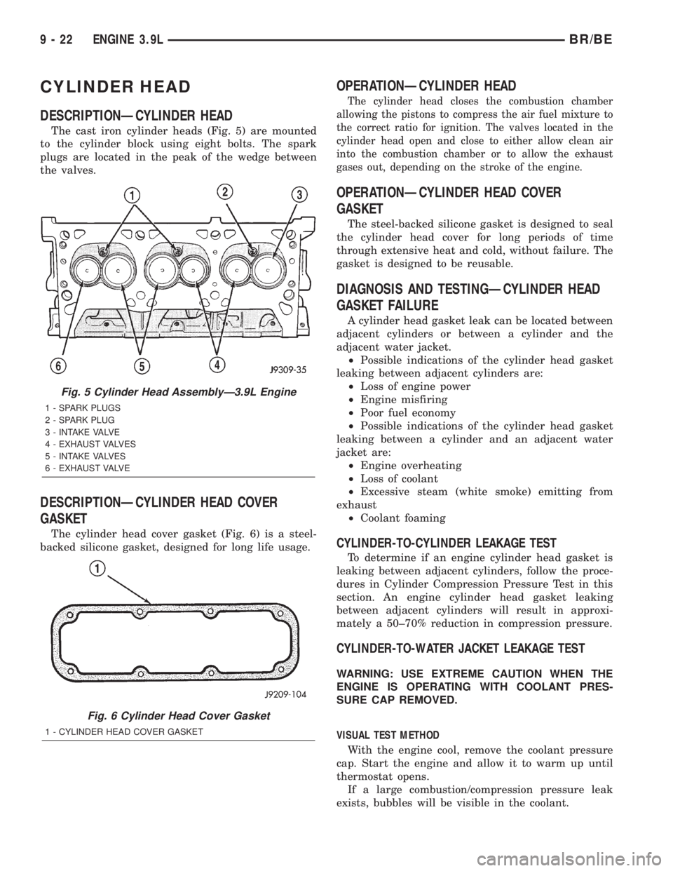
DESCRIPTIONÐCYLINDER HEAD
The cast iron cylinder heads (Fig. 5) are mounted
to the cylinder block using eight bolts. The spark
plugs are located in the peak of the wedge between
the valves.
DESCRIPTIONÐCYLINDER HEAD COVER
GASKET
The cylinder head cover gasket (Fig. 6) is a steel-
backed silicone gasket, designed for long life usage.
OPERATIONÐCYLINDER HEAD
The cylinder head closes the combustion chamber
allowing the pistons to compress the air fuel mixture to
the correct ratio for ignition. The valves located in the
cylinder head open and close to either allow clean air
into the combustion chamber or to allow the exhaust
gases out, depending on the stroke of the engine.
OPERATIONÐCYLINDER HEAD COVER
GASKET
The steel-backed silicone gasket is designed to seal
the cylinder head cover for long periods of time
through extensive heat and cold, without failure. The
gasket is designed to be reusable.
DIAGNOSIS AND TESTINGÐCYLINDER HEAD
GASKET FAILURE
A cylinder head gasket leak can be located between
adjacent cylinders or between a cylinder and the
adjacent water jacket.
²Possible indications of the cylinder head gasket
leaking between adjacent cylinders are:
²Loss of engine power
²Engine misfiring
²Poor fuel economy
²Possible indications of the cylinder head gasket
leaking between a cylinder and an adjacent water
jacket are:
²Engine overheating
²Loss of coolant
²Excessive steam (white smoke) emitting from
exhaust
²Coolant foaming
CYLINDER-TO-CYLINDER LEAKAGE TEST
To determine if an engine cylinder head gasket is
leaking between adjacent cylinders, follow the proce-
dures in Cylinder Compression Pressure Test in this
section. An engine cylinder head gasket leaking
between adjacent cylinders will result in approxi-
mately a 50±70% reduction in compression pressure.
CYLINDER-TO-WATER JACKET LEAKAGE TEST
WARNING: USE EXTREME CAUTION WHEN THE
ENGINE IS OPERATING WITH COOLANT PRES-
SURE CAP REMOVED.
VISUAL TEST METHOD
With the engine cool, remove the coolant pressure
cap. Start the engine and allow it to warm up until
thermostat opens.
If a large combustion/compression pressure leak
exists, bubbles will be visible in the coolant.
Fig. 5 Cylinder Head AssemblyÐ3.9L Engine
1 - SPARK PLUGS
2 - SPARK PLUG
3 - INTAKE VALVE
4 - EXHAUST VALVES
5 - INTAKE VALVES
6 - EXHAUST VALVE
Fig. 6 Cylinder Head Cover Gasket
1 - CYLINDER HEAD COVER GASKET
9 - 22 ENGINE 3.9LBR/BE
Page 1187 of 2889
PISTON & CONNECTING ROD
DESCRIPTION
The pistons are made of aluminum and have three
ring grooves, the top two grooves are for the compres-
sion rings and the bottom groove is for the oil control
ring. The connecting rods are forged steel and are
coined prior to heat treat. The piston pins are press
fit.
STANDARD PROCEDUREÐPISTON FITTING
Check the cylinder block bore for out-of-round,
taper, scoring, or scuffing.
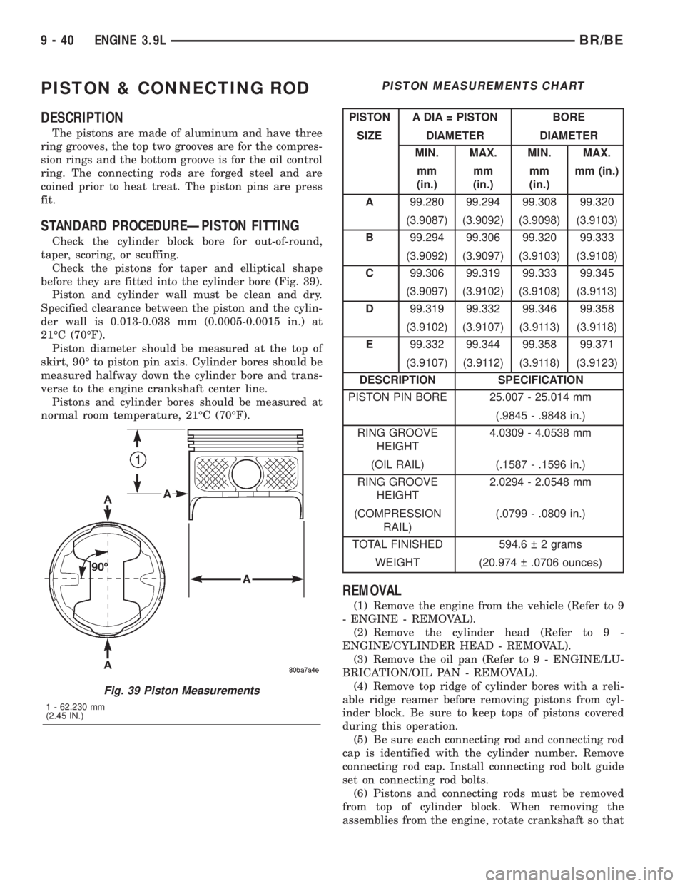
Check the pistons for taper and elliptical shape
before they are fitted into the cylinder bore (Fig. 39).
Piston and cylinder wall must be clean and dry.
Specified clearance between the piston and the cylin-
der wall is 0.013-0.038 mm (0.0005-0.0015 in.) at
21ÉC (70ÉF).
Piston diameter should be measured at the top of
skirt, 90É to piston pin axis. Cylinder bores should be
measured halfway down the cylinder bore and trans-
verse to the engine crankshaft center line.
Pistons and cylinder bores should be measured at
normal room temperature, 21ÉC (70ÉF).
PISTON MEASUREMENTS CHART
PISTON A DIA = PISTON BORE
SIZE DIAMETER DIAMETER
MIN. MAX. MIN. MAX.
mm
(in.)mm
(in.)mm
(in.)mm (in.)
A99.280 99.294 99.308 99.320
(3.9087) (3.9092) (3.9098) (3.9103)
B99.294 99.306 99.320 99.333
(3.9092) (3.9097) (3.9103) (3.9108)
C99.306 99.319 99.333 99.345
(3.9097) (3.9102) (3.9108) (3.9113)
D99.319 99.332 99.346 99.358
(3.9102) (3.9107) (3.9113) (3.9118)
E99.332 99.344 99.358 99.371
(3.9107) (3.9112) (3.9118) (3.9123)
DESCRIPTION SPECIFICATION
PISTON PIN BORE 25.007 - 25.014 mm
(.9845 - .9848 in.)
RING GROOVE
HEIGHT4.0309 - 4.0538 mm
(OIL RAIL) (.1587 - .1596 in.)
RING GROOVE
HEIGHT2.0294 - 2.0548 mm
(COMPRESSION
RAIL)(.0799 - .0809 in.)
TOTAL FINISHED 594.6 2 grams
WEIGHT (20.974 .0706 ounces)
REMOVAL
(1) Remove the engine from the vehicle (Refer to 9
- ENGINE - REMOVAL).
(2) Remove the cylinder head (Refer to 9 -
ENGINE/CYLINDER HEAD - REMOVAL).
(3) Remove the oil pan (Refer to 9 - ENGINE/LU-
BRICATION/OIL PAN - REMOVAL).
(4) Remove top ridge of cylinder bores with a reli-
able ridge reamer before removing pistons from cyl-
inder block. Be sure to keep tops of pistons covered
during this operation.
(5) Be sure each connecting rod and connecting rod
cap is identified with the cylinder number. Remove
connecting rod cap. Install connecting rod bolt guide
set on connecting rod bolts.
(6) Pistons and connecting rods must be removed
from top of cylinder block. When removing the
assemblies from the engine, rotate crankshaft so that
Fig. 39 Piston Measurements
1 - 62.230 mm
(2.45 IN.)
9 - 40 ENGINE 3.9LBR/BE