2001 DODGE RAM compression ratio
[x] Cancel search: compression ratioPage 1303 of 2889
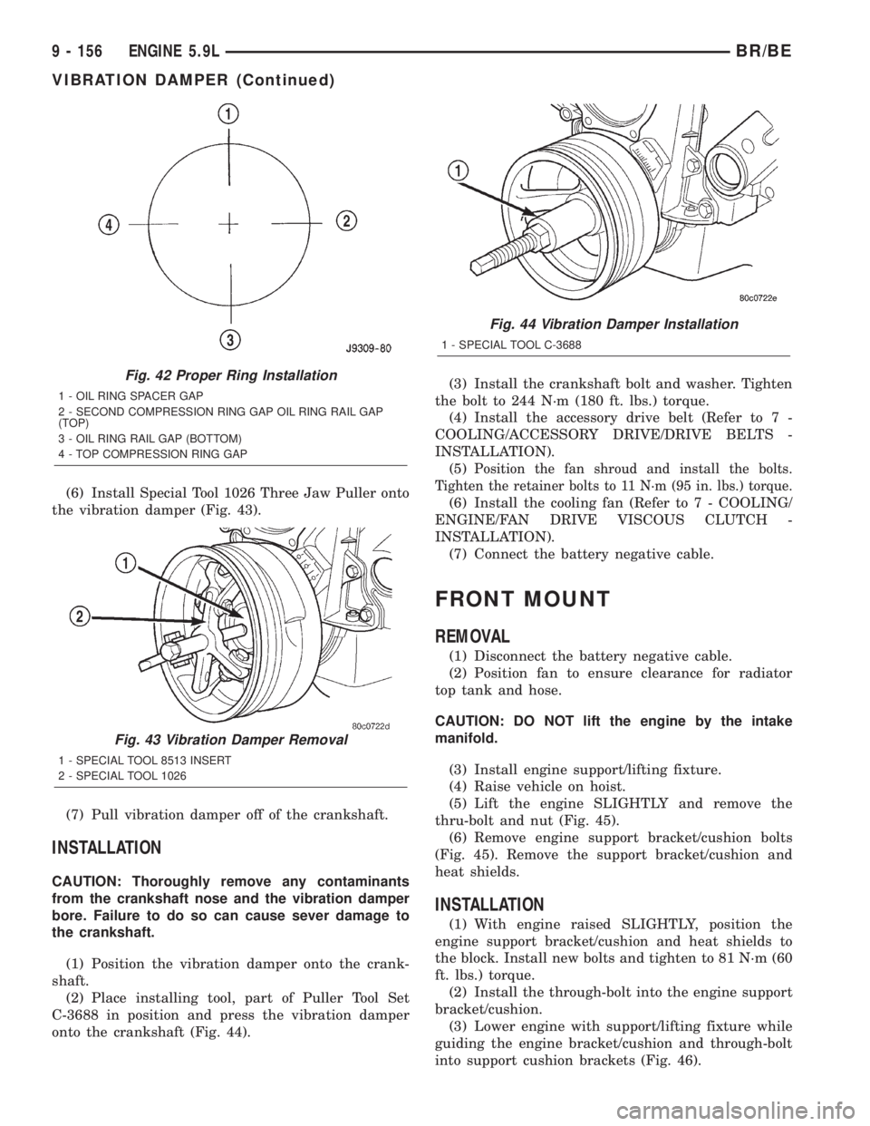
(6) Install Special Tool 1026 Three Jaw Puller onto
the vibration damper (Fig. 43).
(7) Pull vibration damper off of the crankshaft.
INSTALLATION
CAUTION: Thoroughly remove any contaminants
from the crankshaft nose and the vibration damper
bore. Failure to do so can cause sever damage to
the crankshaft.
(1) Position the vibration damper onto the crank-
shaft.
(2) Place installing tool, part of Puller Tool Set
C-3688 in position and press the vibration damper
onto the crankshaft (Fig. 44).(3) Install the crankshaft bolt and washer. Tighten
the bolt to 244 N´m (180 ft. lbs.) torque.
(4) Install the accessory drive belt (Refer to 7 -
COOLING/ACCESSORY DRIVE/DRIVE BELTS -
INSTALLATION).
(5)
Position the fan shroud and install the bolts.
Tighten the retainer bolts to 11 N´m (95 in. lbs.) torque.
(6) Install the cooling fan (Refer to 7 - COOLING/
ENGINE/FAN DRIVE VISCOUS CLUTCH -
INSTALLATION).
(7) Connect the battery negative cable.
FRONT MOUNT
REMOVAL
(1) Disconnect the battery negative cable.
(2) Position fan to ensure clearance for radiator
top tank and hose.
CAUTION: DO NOT lift the engine by the intake
manifold.
(3) Install engine support/lifting fixture.
(4) Raise vehicle on hoist.
(5) Lift the engine SLIGHTLY and remove the
thru-bolt and nut (Fig. 45).
(6) Remove engine support bracket/cushion bolts
(Fig. 45). Remove the support bracket/cushion and
heat shields.
INSTALLATION
(1) With engine raised SLIGHTLY, position the
engine support bracket/cushion and heat shields to
the block. Install new bolts and tighten to 81 N´m (60
ft. lbs.) torque.
(2) Install the through-bolt into the engine support
bracket/cushion.
(3) Lower engine with support/lifting fixture while
guiding the engine bracket/cushion and through-bolt
into support cushion brackets (Fig. 46).
Fig. 42 Proper Ring Installation
1 - OIL RING SPACER GAP
2 - SECOND COMPRESSION RING GAP OIL RING RAIL GAP
(TOP)
3 - OIL RING RAIL GAP (BOTTOM)
4 - TOP COMPRESSION RING GAP
Fig. 43 Vibration Damper Removal
1 - SPECIAL TOOL 8513 INSERT
2 - SPECIAL TOOL 1026
Fig. 44 Vibration Damper Installation
1 - SPECIAL TOOL C-3688
9 - 156 ENGINE 5.9LBR/BE
VIBRATION DAMPER (Continued)
Page 1318 of 2889
ENGINE 8.0L
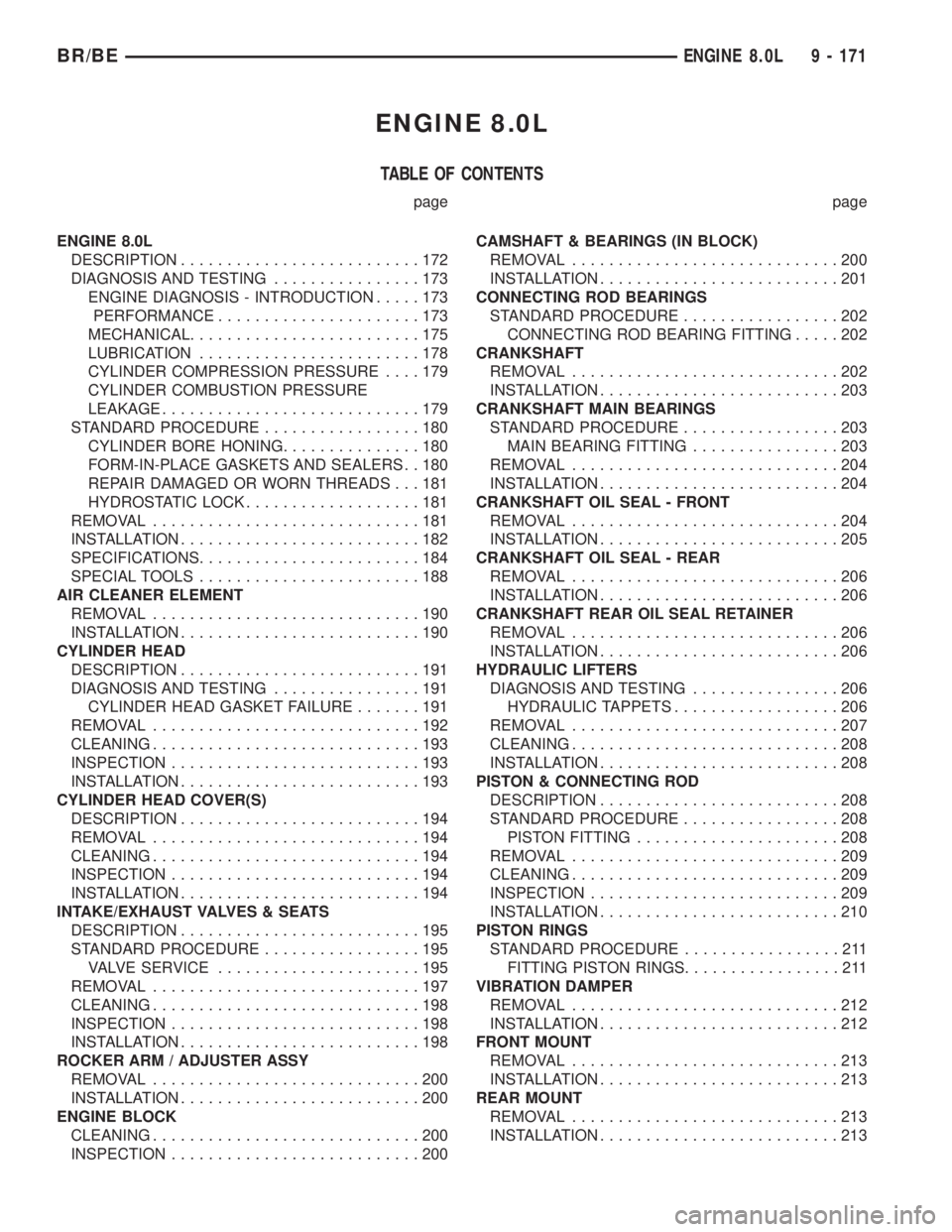
TABLE OF CONTENTS
page page
ENGINE 8.0L
DESCRIPTION..........................172
DIAGNOSIS AND TESTING................173
ENGINE DIAGNOSIS - INTRODUCTION.....173
PERFORMANCE......................173
MECHANICAL.........................175
LUBRICATION........................178
CYLINDER COMPRESSION PRESSURE....179
CYLINDER COMBUSTION PRESSURE
LEAKAGE............................179
STANDARD PROCEDURE.................180
CYLINDER BORE HONING...............180
FORM-IN-PLACE GASKETS AND SEALERS . . 180
REPAIR DAMAGED OR WORN THREADS . . . 181
HYDROSTATIC LOCK...................181
REMOVAL.............................181
INSTALLATION..........................182
SPECIFICATIONS........................184
SPECIAL TOOLS........................188
AIR CLEANER ELEMENT
REMOVAL.............................190
INSTALLATION..........................190
CYLINDER HEAD
DESCRIPTION..........................191
DIAGNOSIS AND TESTING................191
CYLINDER HEAD GASKET FAILURE.......191
REMOVAL.............................192
CLEANING.............................193
INSPECTION...........................193
INSTALLATION..........................193
CYLINDER HEAD COVER(S)
DESCRIPTION..........................194
REMOVAL.............................194
CLEANING.............................194
INSPECTION...........................194
INSTALLATION..........................194
INTAKE/EXHAUST VALVES & SEATS
DESCRIPTION..........................195
STANDARD PROCEDURE.................195
VALVE SERVICE......................195
REMOVAL.............................197
CLEANING.............................198
INSPECTION...........................198
INSTALLATION..........................198
ROCKER ARM / ADJUSTER ASSY
REMOVAL.............................200
INSTALLATION..........................200
ENGINE BLOCK
CLEANING.............................200
INSPECTION...........................200CAMSHAFT & BEARINGS (IN BLOCK)
REMOVAL.............................200
INSTALLATION..........................201
CONNECTING ROD BEARINGS
STANDARD PROCEDURE.................202
CONNECTING ROD BEARING FITTING.....202
CRANKSHAFT
REMOVAL.............................202
INSTALLATION..........................203
CRANKSHAFT MAIN BEARINGS
STANDARD PROCEDURE.................203
MAIN BEARING FITTING................203
REMOVAL.............................204
INSTALLATION..........................204
CRANKSHAFT OIL SEAL - FRONT
REMOVAL.............................204
INSTALLATION..........................205
CRANKSHAFT OIL SEAL - REAR
REMOVAL.............................206
INSTALLATION..........................206
CRANKSHAFT REAR OIL SEAL RETAINER
REMOVAL.............................206
INSTALLATION..........................206
HYDRAULIC LIFTERS
DIAGNOSIS AND TESTING................206
HYDRAULIC TAPPETS..................206
REMOVAL.............................207
CLEANING.............................208
INSTALLATION..........................208
PISTON & CONNECTING ROD
DESCRIPTION..........................208
STANDARD PROCEDURE.................208
PISTON FITTING......................208
REMOVAL.............................209
CLEANING.............................209
INSPECTION...........................209
INSTALLATION..........................210
PISTON RINGS
STANDARD PROCEDURE.................211
FITTING PISTON RINGS.................211
VIBRATION DAMPER
REMOVAL.............................212
INSTALLATION..........................212
FRONT MOUNT
REMOVAL.............................213
INSTALLATION..........................213
REAR MOUNT
REMOVAL.............................213
INSTALLATION..........................213
BR/BEENGINE 8.0L 9 - 171
Page 1333 of 2889
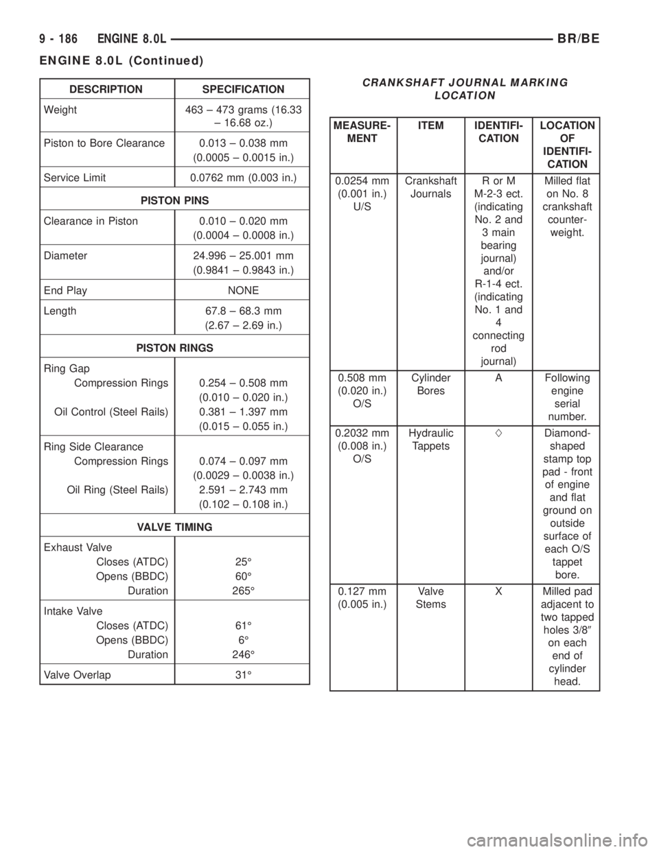
DESCRIPTION SPECIFICATION
Weight 463 ± 473 grams (16.33
± 16.68 oz.)
Piston to Bore Clearance 0.013 ± 0.038 mm
(0.0005 ± 0.0015 in.)
Service Limit 0.0762 mm (0.003 in.)
PISTON PINS
Clearance in Piston 0.010 ± 0.020 mm
(0.0004 ± 0.0008 in.)
Diameter 24.996 ± 25.001 mm
(0.9841 ± 0.9843 in.)
End Play NONE
Length 67.8 ± 68.3 mm
(2.67 ± 2.69 in.)
PISTON RINGS
Ring Gap
Compression Rings 0.254 ± 0.508 mm
(0.010 ± 0.020 in.)
Oil Control (Steel Rails) 0.381 ± 1.397 mm
(0.015 ± 0.055 in.)
Ring Side Clearance
Compression Rings 0.074 ± 0.097 mm
(0.0029 ± 0.0038 in.)
Oil Ring (Steel Rails) 2.591 ± 2.743 mm
(0.102 ± 0.108 in.)
VALVE TIMING
Exhaust Valve
Closes (ATDC) 25É
Opens (BBDC) 60É
Duration 265É
Intake Valve
Closes (ATDC) 61É
Opens (BBDC) 6É
Duration 246É
Valve Overlap 31ÉCRANKSHAFT JOURNAL MARKING
LOCATION
MEASURE-
MENTITEM IDENTIFI-
CATIONLOCATION
OF
IDENTIFI-
CATION
0.0254 mm
(0.001 in.)
U/SCrankshaft
JournalsRorM
M-2-3 ect.
(indicating
No. 2 and
3 main
bearing
journal)
and/or
R-1-4 ect.
(indicating
No. 1 and
4
connecting
rod
journal)Milled flat
on No. 8
crankshaft
counter-
weight.
0.508 mm
(0.020 in.)
O/SCylinder
BoresA Following
engine
serial
number.
0.2032 mm
(0.008 in.)
O/SHydraulic
TappetsLDiamond-
shaped
stamp top
pad - front
of engine
and flat
ground on
outside
surface of
each O/S
tappet
bore.
0.127 mm
(0.005 in.)Valve
StemsX Milled pad
adjacent to
two tapped
holes 3/89
on each
end of
cylinder
head.
9 - 186 ENGINE 8.0LBR/BE
ENGINE 8.0L (Continued)
Page 1357 of 2889
Check the piston for scoring, or scraping marks in
the piston skirts. Check the ring lands for cracks
and/or deterioration.
INSTALLATION
(1) Check the crankshaft connecting rod journal
for excessive wear, taper and scoring.
(2) Check the cylinder block bore for out-of-round,
taper, scoring and scuffing.
(3) Be sure that compression ring gaps are stag-
gered so that neither is in line with oil ring rail gap.
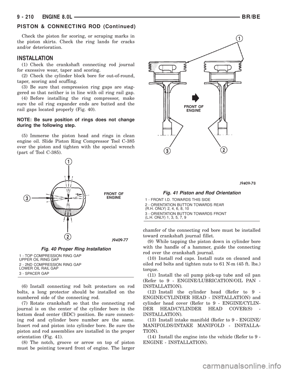
(4) Before installing the ring compressor, make
sure the oil ring expander ends are butted and the
rail gaps located properly (Fig. 40).
NOTE: Be sure position of rings does not change
during the following step.
(5) Immerse the piston head and rings in clean
engine oil. Slide Piston Ring Compressor Tool C-385
over the piston and tighten with the special wrench
(part of Tool C-385).
(6) Install connecting rod bolt protectors on rod
bolts, a long protector should be installed on the
numbered side of the connecting rod.
(7) Rotate crankshaft so that the connecting rod
journal is on the center of the cylinder bore in the
bottom dead center (BDC) position. Be sure connect-
ing rod and cylinder bore number are the same.
Insert rod and piston into cylinder bore. Be sure the
piston and rod assemblies are installed in the proper
orientation (Fig. 41).
(8) The notch, groove or arrow on top of piston
must be pointing toward front of engine. The largerchamfer of the connecting rod bore must be installed
toward crankshaft journal fillet.
(9) While tapping the piston down in cylinder bore
with the handle of a hammer, guide the connecting
rod over the crankshaft journal.
(10) Install rod caps. Install nuts on cleaned and
oiled rod bolts and tighten nuts to 61 N´m (45 ft. lbs.)
torque.
(11) Install the oil pump pick-up tube and oil pan
(Refer to 9 - ENGINE/LUBRICATION/OIL PAN -
INSTALLATION).
(12) Install the cylinder head (Refer to 9 -
ENGINE/CYLINDER HEAD - INSTALLATION) and
cylinder head cover (Refer to 9 - ENGINE/CYLIN-
DER HEAD/CYLINDER HEAD COVER(S) -
INSTALLATION).
(13) Install intake manifold (Refer to 9 - ENGINE/
MANIFOLDS/INTAKE MANIFOLD - INSTALLA-
TION).
(14) Install the engine into the vehicle (Refer to 9 -
ENGINE - INSTALLATION).
Fig. 40 Proper Ring Installation
1 - TOP COMPRESSION RING GAP
UPPER OIL RING GAP
2 - 2ND COMPRESSION RING GAP
LOWER OIL RAIL GAP
3 - SPACER GAP
Fig. 41 Piston and Rod Orientation
1 - FRONT I.D. TOWARDS THIS SIDE
2 - ORIENTATION BUTTON TOWARDS REAR
(R.H. ONLY) 2, 4, 6, 8, 10
3 - ORIENTATION BUTTON TOWARDS FRONT
(L.H. ONLY) 1, 3, 5, 7, 9
9 - 210 ENGINE 8.0LBR/BE
PISTON & CONNECTING ROD (Continued)
Page 1359 of 2889
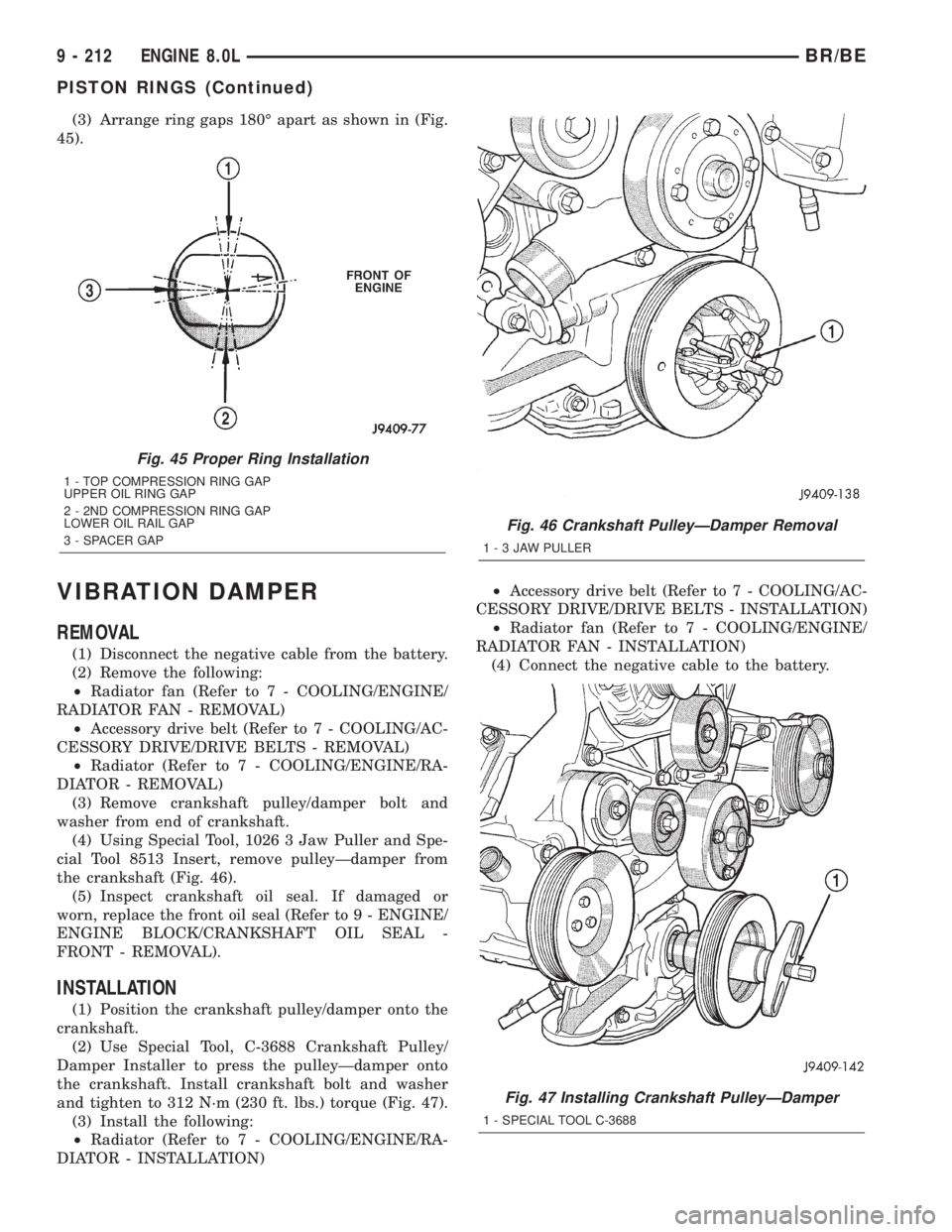
(3) Arrange ring gaps 180É apart as shown in (Fig.
45).
VIBRATION DAMPER
REMOVAL
(1) Disconnect the negative cable from the battery.
(2) Remove the following:
²Radiator fan (Refer to 7 - COOLING/ENGINE/
RADIATOR FAN - REMOVAL)
²Accessory drive belt (Refer to 7 - COOLING/AC-
CESSORY DRIVE/DRIVE BELTS - REMOVAL)
²Radiator (Refer to 7 - COOLING/ENGINE/RA-
DIATOR - REMOVAL)
(3) Remove crankshaft pulley/damper bolt and
washer from end of crankshaft.
(4) Using Special Tool, 1026 3 Jaw Puller and Spe-
cial Tool 8513 Insert, remove pulleyÐdamper from
the crankshaft (Fig. 46).
(5) Inspect crankshaft oil seal. If damaged or
worn, replace the front oil seal (Refer to 9 - ENGINE/
ENGINE BLOCK/CRANKSHAFT OIL SEAL -
FRONT - REMOVAL).
INSTALLATION
(1) Position the crankshaft pulley/damper onto the
crankshaft.
(2) Use Special Tool, C-3688 Crankshaft Pulley/
Damper Installer to press the pulleyÐdamper onto
the crankshaft. Install crankshaft bolt and washer
and tighten to 312 N´m (230 ft. lbs.) torque (Fig. 47).
(3) Install the following:
²Radiator (Refer to 7 - COOLING/ENGINE/RA-
DIATOR - INSTALLATION)²Accessory drive belt (Refer to 7 - COOLING/AC-
CESSORY DRIVE/DRIVE BELTS - INSTALLATION)
²Radiator fan (Refer to 7 - COOLING/ENGINE/
RADIATOR FAN - INSTALLATION)
(4) Connect the negative cable to the battery.
Fig. 45 Proper Ring Installation
1 - TOP COMPRESSION RING GAP
UPPER OIL RING GAP
2 - 2ND COMPRESSION RING GAP
LOWER OIL RAIL GAP
3 - SPACER GAP
Fig. 46 Crankshaft PulleyÐDamper Removal
1-3JAWPULLER
Fig. 47 Installing Crankshaft PulleyÐDamper
1 - SPECIAL TOOL C-3688
9 - 212 ENGINE 8.0LBR/BE
PISTON RINGS (Continued)
Page 1380 of 2889
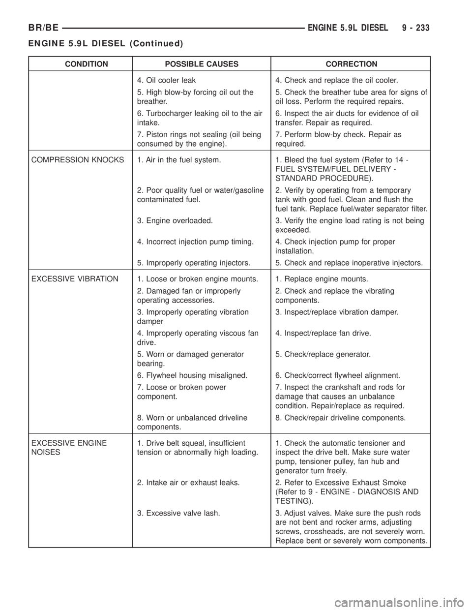
CONDITION POSSIBLE CAUSES CORRECTION
4. Oil cooler leak 4. Check and replace the oil cooler.
5. High blow-by forcing oil out the
breather.5. Check the breather tube area for signs of
oil loss. Perform the required repairs.
6. Turbocharger leaking oil to the air
intake.6. Inspect the air ducts for evidence of oil
transfer. Repair as required.
7. Piston rings not sealing (oil being
consumed by the engine).7. Perform blow-by check. Repair as
required.
COMPRESSION KNOCKS 1. Air in the fuel system. 1. Bleed the fuel system (Refer to 14 -
FUEL SYSTEM/FUEL DELIVERY -
STANDARD PROCEDURE).
2. Poor quality fuel or water/gasoline
contaminated fuel.2. Verify by operating from a temporary
tank with good fuel. Clean and flush the
fuel tank. Replace fuel/water separator filter.
3. Engine overloaded. 3. Verify the engine load rating is not being
exceeded.
4. Incorrect injection pump timing. 4. Check injection pump for proper
installation.
5. Improperly operating injectors. 5. Check and replace inoperative injectors.
EXCESSIVE VIBRATION 1. Loose or broken engine mounts. 1. Replace engine mounts.
2. Damaged fan or improperly
operating accessories.2. Check and replace the vibrating
components.
3. Improperly operating vibration
damper3. Inspect/replace vibration damper.
4. Improperly operating viscous fan
drive.4. Inspect/replace fan drive.
5. Worn or damaged generator
bearing.5. Check/replace generator.
6. Flywheel housing misaligned. 6. Check/correct flywheel alignment.
7. Loose or broken power
component.7. Inspect the crankshaft and rods for
damage that causes an unbalance
condition. Repair/replace as required.
8. Worn or unbalanced driveline
components.8. Check/repair driveline components.
EXCESSIVE ENGINE
NOISES1. Drive belt squeal, insufficient
tension or abnormally high loading.1. Check the automatic tensioner and
inspect the drive belt. Make sure water
pump, tensioner pulley, fan hub and
generator turn freely.
2. Intake air or exhaust leaks. 2. Refer to Excessive Exhaust Smoke
(Refer to 9 - ENGINE - DIAGNOSIS AND
TESTING).
3. Excessive valve lash. 3. Adjust valves. Make sure the push rods
are not bent and rocker arms, adjusting
screws, crossheads, are not severely worn.
Replace bent or severely worn components.
BR/BEENGINE 5.9L DIESEL 9 - 233
ENGINE 5.9L DIESEL (Continued)
Page 1389 of 2889
(23) Connect the transmission quick-connect oil
cooler lines to the radiator. Push together until an
audible ªclickº is heard. Verify connection by pulling
apart.
(24) Raise vehicle.
(25) Connect a/c compressor suction/discharge hose
(if a/c equipped).
(26) Install the radiator lower hose and clamps.
(27) Install the starter motor (Refer to 8 - ELEC-
TRICAL/STARTING/STARTER MOTOR - INSTAL-
LATION).
(28) Install the transmission and transfer case (if
equipped).
(29) Connect the exhaust pipe to the turbocharger
elbow (Fig. 3). Torque the bolts to 34 N´m (25 ft. lbs.)
torque.
(30) Connect the transmission auxiliary oil cooler
lines (if equipped).
(31) Lower the vehicle
(32) Connect the heater core supply and return
hoses.
(33) Install the cooling fan and shroud at the same
time (Refer to 7 - COOLING/ENGINE/RADIATOR
FAN - INSTALLATION).
(34) Install the coolant recovery bottle to the fan
shroud (Fig. 2) and connect the hose to the radiator
filler neck.
(35) Install the windshield washer bottle to the fan
shroud and connect the pump supply hose and elec-
trical connections.
(36) Install the radiator upper hose and clamps.
(37) Change oil filter and install new engine oil.
(38) Fill cooling system with coolant (Refer to 7 -
COOLING - STANDARD PROCEDURE).
(39) Connect battery negative cables.
(40) Perform the fuel line air bleed procedure
(Refer to 14 - FUEL SYSTEM/FUEL DELIVERY -
STANDARD PROCEDURE).
(41) Start engine and inspect for engine oil, cool-
ant, and fuel leaks.
INSTALLATIONÐCRANKCASE BREATHER
VAPOR CANISTER
(1) Position vapor canister with strap over stud on
engine front cover. Install retaining nut. Tighten nut
10 N´m ( 89 in. lbs.).
(2) If removed, position hose onto crankcase
breather, then position clamp.
(3) Position lower portion of hose into vapor canis-
ter, then install and tighten cap.
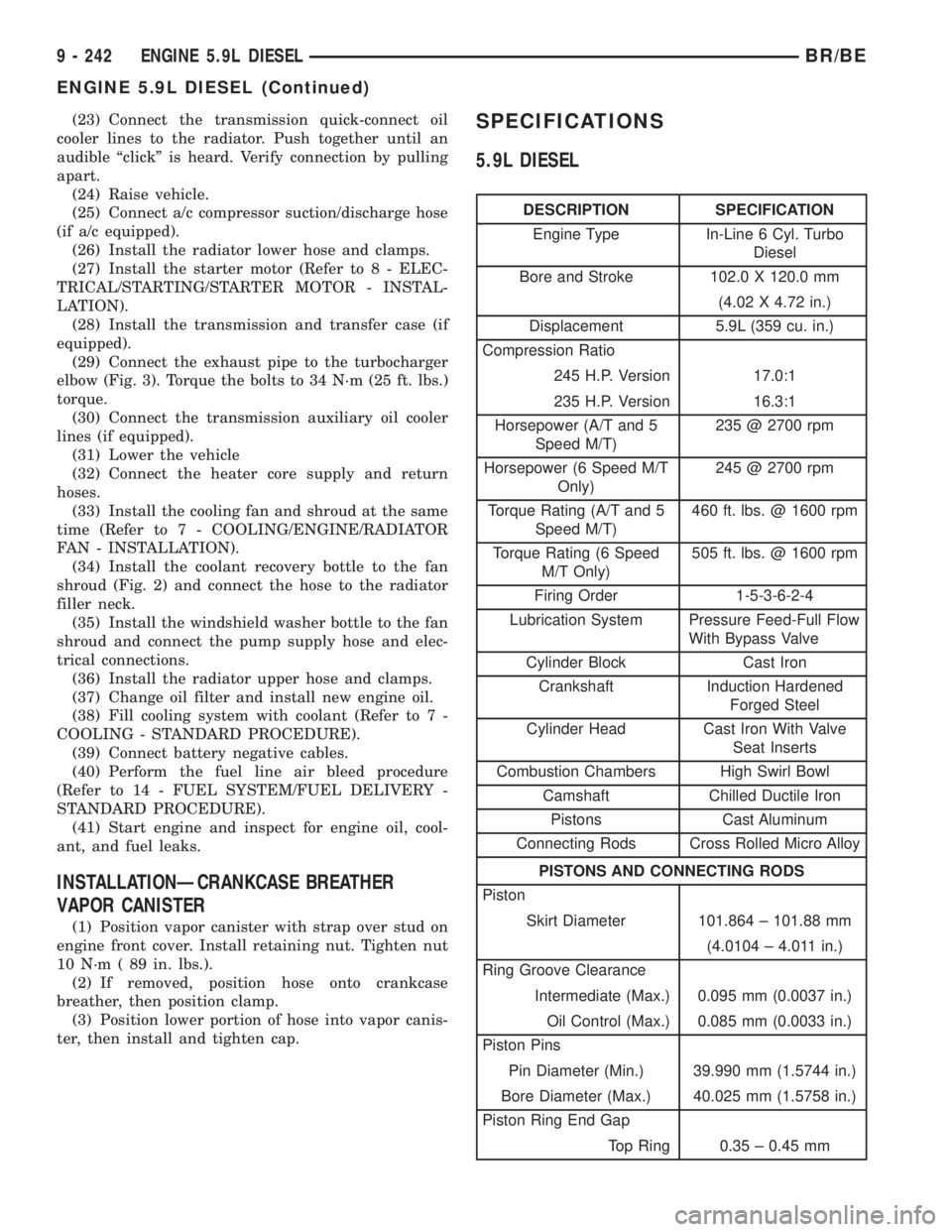
SPECIFICATIONS
5.9L DIESEL
DESCRIPTION SPECIFICATION
Engine Type In-Line 6 Cyl. Turbo
Diesel
Bore and Stroke 102.0 X 120.0 mm
(4.02 X 4.72 in.)
Displacement 5.9L (359 cu. in.)
Compression Ratio
245 H.P. Version 17.0:1
235 H.P. Version 16.3:1
Horsepower (A/T and 5
Speed M/T)235 @ 2700 rpm
Horsepower (6 Speed M/T
Only)245 @ 2700 rpm
Torque Rating (A/T and 5
Speed M/T)460 ft. lbs. @ 1600 rpm
Torque Rating (6 Speed
M/T Only)505 ft. lbs. @ 1600 rpm
Firing Order 1-5-3-6-2-4
Lubrication System Pressure Feed-Full Flow
With Bypass Valve
Cylinder Block Cast Iron
Crankshaft Induction Hardened
Forged Steel
Cylinder Head Cast Iron With Valve
Seat Inserts
Combustion Chambers High Swirl Bowl
Camshaft Chilled Ductile Iron
Pistons Cast Aluminum
Connecting Rods Cross Rolled Micro Alloy
PISTONS AND CONNECTING RODS
Piston
Skirt Diameter 101.864 ± 101.88 mm
(4.0104 ± 4.011 in.)
Ring Groove Clearance
Intermediate (Max.) 0.095 mm (0.0037 in.)
Oil Control (Max.) 0.085 mm (0.0033 in.)
Piston Pins
Pin Diameter (Min.) 39.990 mm (1.5744 in.)
Bore Diameter (Max.) 40.025 mm (1.5758 in.)
Piston Ring End Gap
Top Ring 0.35 ± 0.45 mm
9 - 242 ENGINE 5.9L DIESELBR/BE
ENGINE 5.9L DIESEL (Continued)
Page 1468 of 2889
(6) Start the engine and inspect for exhaust leaks
and exhaust system contact with the body panels.
Adjust the alignment, if needed.
RESONATOR
REMOVAL
(1) Disconnect the battery negative cables.
(2) Raise vehicle on hoist.
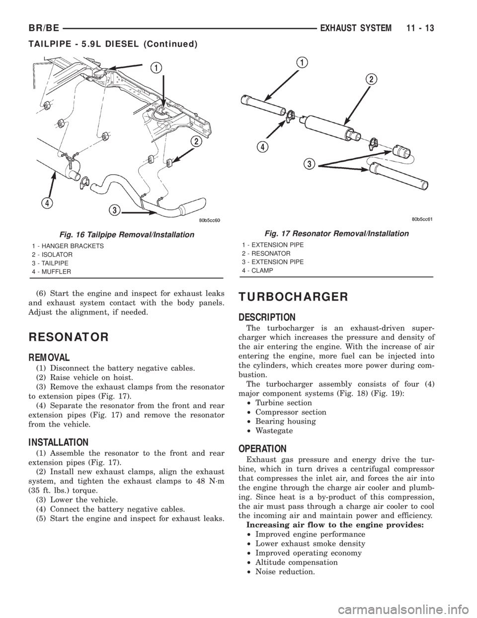
(3) Remove the exhaust clamps from the resonator
to extension pipes (Fig. 17).
(4) Separate the resonator from the front and rear
extension pipes (Fig. 17) and remove the resonator
from the vehicle.
INSTALLATION
(1) Assemble the resonator to the front and rear
extension pipes (Fig. 17).
(2) Install new exhaust clamps, align the exhaust
system, and tighten the exhaust clamps to 48 N´m
(35 ft. lbs.) torque.
(3) Lower the vehicle.
(4) Connect the battery negative cables.
(5) Start the engine and inspect for exhaust leaks.
TURBOCHARGER
DESCRIPTION
The turbocharger is an exhaust-driven super-
charger which increases the pressure and density of
the air entering the engine. With the increase of air
entering the engine, more fuel can be injected into
the cylinders, which creates more power during com-
bustion.
The turbocharger assembly consists of four (4)
major component systems (Fig. 18) (Fig. 19):
²Turbine section
²Compressor section
²Bearing housing
²Wastegate
OPERATION
Exhaust gas pressure and energy drive the tur-
bine, which in turn drives a centrifugal compressor
that compresses the inlet air, and forces the air into
the engine through the charge air cooler and plumb-
ing. Since heat is a by-product of this compression,
the air must pass through a charge air cooler to cool
the incoming air and maintain power and efficiency.
Increasing air flow to the engine provides:
²Improved engine performance
²Lower exhaust smoke density
²Improved operating economy
²Altitude compensation
²Noise reduction.
Fig. 16 Tailpipe Removal/Installation
1 - HANGER BRACKETS
2 - ISOLATOR
3 - TAILPIPE
4 - MUFFLER
Fig. 17 Resonator Removal/Installation
1 - EXTENSION PIPE
2 - RESONATOR
3 - EXTENSION PIPE
4 - CLAMP
BR/BEEXHAUST SYSTEM 11 - 13
TAILPIPE - 5.9L DIESEL (Continued)