2001 DODGE RAM compression ratio
[x] Cancel search: compression ratioPage 1188 of 2889
the connecting rod is centered in cylinder bore and at
BDC.Be careful not to nick crankshaft journals.
(7) After removal, install bearing cap on the mat-
ing rod.
CLEANING
Clean the piston and connecting rod assembly
using a suitable solvent.
INSPECTION
Check the connecting rod journal for excessive
wear, taper and scoring (Refer to 9 - ENGINE/EN-
GINE BLOCK/CONNECTING ROD BEARINGS -
STANDARD PROCEDURE).
Check the connecting rod for signs of twist or bend-
ing.
Check the piston for taper and elliptical shape
before it is fitted into the cylinder bore (Refer to 9 -
ENGINE/ENGINE BLOCK/PISTON & CONNECT-
ING ROD - STANDARD PROCEDURE).
Check the piston for scoring, or scraping marks in
the piston skirts. Check the ring lands for cracks
and/or deterioration.
INSTALLATION
(1) Be sure that compression ring gaps are stag-
gered so that neither is in line with oil ring rail gap.
(2) Before installing the ring compressor, be sure
the oil ring expander ends are butted and the rail
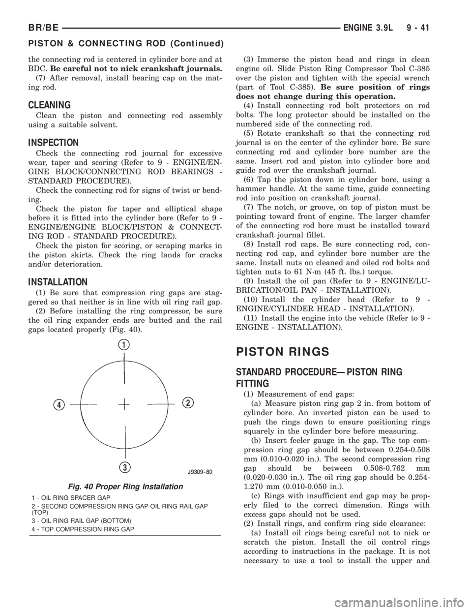
gaps located properly (Fig. 40).(3) Immerse the piston head and rings in clean
engine oil. Slide Piston Ring Compressor Tool C-385
over the piston and tighten with the special wrench
(part of Tool C-385).Be sure position of rings
does not change during this operation.
(4) Install connecting rod bolt protectors on rod
bolts. The long protector should be installed on the
numbered side of the connecting rod.
(5) Rotate crankshaft so that the connecting rod
journal is on the center of the cylinder bore. Be sure
connecting rod and cylinder bore number are the
same. Insert rod and piston into cylinder bore and
guide rod over the crankshaft journal.
(6) Tap the piston down in cylinder bore, using a
hammer handle. At the same time, guide connecting
rod into position on crankshaft journal.
(7) The notch, or groove, on top of piston must be
pointing toward front of engine. The larger chamfer
of the connecting rod bore must be installed toward
crankshaft journal fillet.
(8) Install rod caps. Be sure connecting rod, con-
necting rod cap, and cylinder bore number are the
same. Install nuts on cleaned and oiled rod bolts and
tighten nuts to 61 N´m (45 ft. lbs.) torque.
(9) Install the oil pan (Refer to 9 - ENGINE/LU-
BRICATION/OIL PAN - INSTALLATION).
(10) Install the cylinder head (Refer to 9 -
ENGINE/CYLINDER HEAD - INSTALLATION).
(11) Install the engine into the vehicle (Refer to 9 -
ENGINE - INSTALLATION).
PISTON RINGS
STANDARD PROCEDUREÐPISTON RING
FITTING
(1) Measurement of end gaps:
(a) Measure piston ring gap 2 in. from bottom of
cylinder bore. An inverted piston can be used to
push the rings down to ensure positioning rings
squarely in the cylinder bore before measuring.
(b) Insert feeler gauge in the gap. The top com-
pression ring gap should be between 0.254-0.508
mm (0.010-0.020 in.). The second compression ring
gap should be between 0.508-0.762 mm
(0.020-0.030 in.). The oil ring gap should be 0.254-
1.270 mm (0.010-0.050 in.).
(c) Rings with insufficient end gap may be prop-
erly filed to the correct dimension. Rings with
excess gaps should not be used.
(2) Install rings, and confirm ring side clearance:
(a) Install oil rings being careful not to nick or
scratch the piston. Install the oil control rings
according to instructions in the package. It is not
necessary to use a tool to install the upper and
Fig. 40 Proper Ring Installation
1 - OIL RING SPACER GAP
2 - SECOND COMPRESSION RING GAP OIL RING RAIL GAP
(TOP)
3 - OIL RING RAIL GAP (BOTTOM)
4 - TOP COMPRESSION RING GAP
BR/BEENGINE 3.9L 9 - 41
PISTON & CONNECTING ROD (Continued)
Page 1189 of 2889
lower rails. Insert oil rail spacer first, then side
rails.
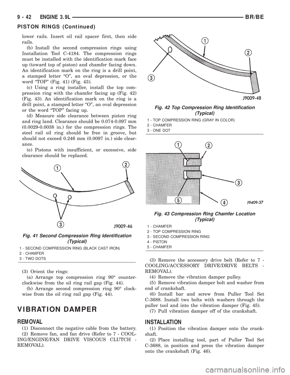
(b) Install the second compression rings using
Installation Tool C-4184. The compression rings
must be installed with the identification mark face
up (toward top of piston) and chamfer facing down.
An identification mark on the ring is a drill point,
a stamped letter ªOº, an oval depression, or the
word ªTOPº (Fig. 41) (Fig. 43).
(c) Using a ring installer, install the top com-
pression ring with the chamfer facing up (Fig. 42)
(Fig. 43). An identification mark on the ring is a
drill point, a stamped letter ªOº, an oval depression
or the word ªTOPº facing up.
(d) Measure side clearance between piston ring
and ring land. Clearance should be 0.074-0.097 mm
(0.0029-0.0038 in.) for the compression rings. The
steel rail oil ring should be free in groove, but
should not exceed 0.246 mm (0.0097 in.) side clear-
ance.
(e) Pistons with insufficient, or excessive, side
clearance should be replaced.
(3) Orient the rings:
(a) Arrange top compression ring 90É counter-
clockwise from the oil ring rail gap (Fig. 44).
(b) Arrange second compression ring 90É clock-
wise from the oil ring rail gap (Fig. 44).
VIBRATION DAMPER
REMOVAL
(1) Disconnect the negative cable from the battery.
(2) Remove fan, and fan drive (Refer to 7 - COOL-
ING/ENGINE/FAN DRIVE VISCOUS CLUTCH -
REMOVAL).(3) Remove the accessory drive belt (Refer to 7 -
COOLING/ACCESSORY DRIVE/DRIVE BELTS -
REMOVAL).
(4) Remove the vibration damper pulley.
(5) Remove vibration damper bolt and washer from
end of crankshaft.
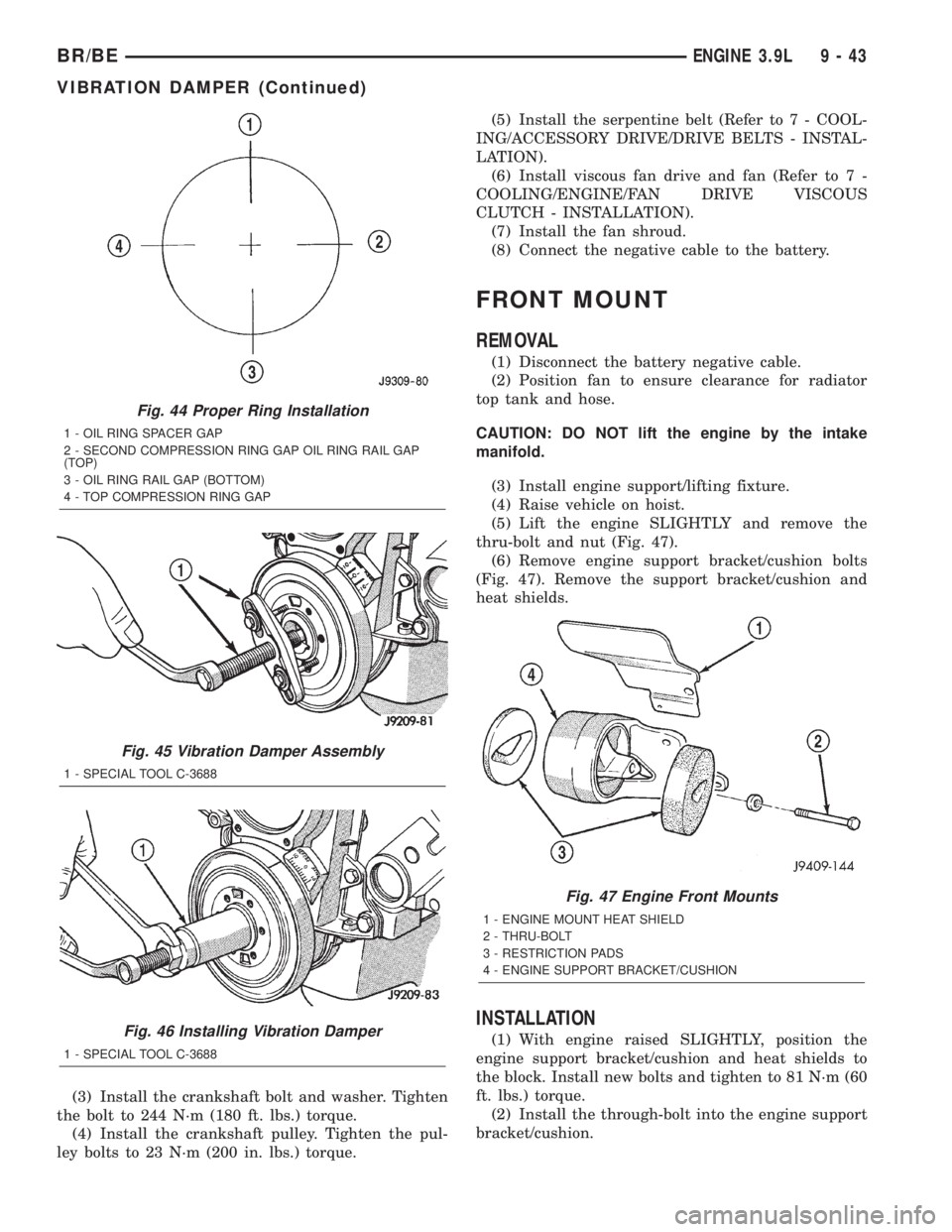
(6) Install bar and screw from Puller Tool Set
C-3688. Install two bolts with washers through the
puller tool and into the vibration damper (Fig. 45).
(7) Pull vibration damper off of the crankshaft.
INSTALLATION
(1) Position the vibration damper onto the crank-
shaft.
(2) Place installing tool, part of Puller Tool Set
C-3688, in position and press the vibration damper
onto the crankshaft (Fig. 46).
Fig. 41 Second Compression Ring Identification
(Typical)
1 - SECOND COMPRESSION RING (BLACK CAST IRON)
2 - CHAMFER
3 - TWO DOTS
Fig. 42 Top Compression Ring Identification
(Typical)
1 - TOP COMPRESSION RING (GRAY IN COLOR)
2 - CHAMFER
3 - ONE DOT
Fig. 43 Compression Ring Chamfer Location
(Typical)
1 - CHAMFER
2 - TOP COMPRESSION RING
3 - SECOND COMPRESSION RING
4 - PISTON
5 - CHAMFER
9 - 42 ENGINE 3.9LBR/BE
PISTON RINGS (Continued)
Page 1190 of 2889
(3) Install the crankshaft bolt and washer. Tighten
the bolt to 244 N´m (180 ft. lbs.) torque.
(4) Install the crankshaft pulley. Tighten the pul-
ley bolts to 23 N´m (200 in. lbs.) torque.(5) Install the serpentine belt (Refer to 7 - COOL-
ING/ACCESSORY DRIVE/DRIVE BELTS - INSTAL-
LATION).
(6) Install viscous fan drive and fan (Refer to 7 -
COOLING/ENGINE/FAN DRIVE VISCOUS
CLUTCH - INSTALLATION).
(7) Install the fan shroud.
(8) Connect the negative cable to the battery.
FRONT MOUNT
REMOVAL
(1) Disconnect the battery negative cable.
(2) Position fan to ensure clearance for radiator
top tank and hose.
CAUTION: DO NOT lift the engine by the intake
manifold.
(3) Install engine support/lifting fixture.
(4) Raise vehicle on hoist.
(5) Lift the engine SLIGHTLY and remove the
thru-bolt and nut (Fig. 47).
(6) Remove engine support bracket/cushion bolts
(Fig. 47). Remove the support bracket/cushion and
heat shields.
INSTALLATION
(1) With engine raised SLIGHTLY, position the
engine support bracket/cushion and heat shields to
the block. Install new bolts and tighten to 81 N´m (60
ft. lbs.) torque.
(2) Install the through-bolt into the engine support
bracket/cushion.
Fig. 44 Proper Ring Installation
1 - OIL RING SPACER GAP
2 - SECOND COMPRESSION RING GAP OIL RING RAIL GAP
(TOP)
3 - OIL RING RAIL GAP (BOTTOM)
4 - TOP COMPRESSION RING GAP
Fig. 45 Vibration Damper Assembly
1 - SPECIAL TOOL C-3688
Fig. 46 Installing Vibration Damper
1 - SPECIAL TOOL C-3688
Fig. 47 Engine Front Mounts
1 - ENGINE MOUNT HEAT SHIELD
2 - THRU-BOLT
3 - RESTRICTION PADS
4 - ENGINE SUPPORT BRACKET/CUSHION
BR/BEENGINE 3.9L 9 - 43
VIBRATION DAMPER (Continued)
Page 1206 of 2889
ENGINE 5.2L
TABLE OF CONTENTS
page page
ENGINE 5.2L
DESCRIPTION...........................60
DIAGNOSIS AND TESTING.................61
ENGINE DIAGNOSIS - INTRODUCTION......61
PERFORMANCE.......................61
MECHANICAL.........................63
LUBRICATION.........................66
CYLINDER COMPRESSION PRESSURE.....67
CYLINDER COMBUSTION PRESSURE
LEAKAGE.............................67
STANDARD PROCEDURE..................68
FORM-IN-PLACE GASKETS AND SEALERS. . . 68
REPAIR DAMAGED OR WORN THREADS....68
HYDROSTATIC LOCK....................68
CYLINDER BORE HONING...............69
REMOVAL..............................69
INSTALLATION...........................70
SPECIFICATIONS........................72
SPECIAL TOOLS.........................77
CYLINDER HEAD
DESCRIPTION...........................79
OPERATION.............................79
DIAGNOSIS AND TESTING.................79
CYLINDER HEAD GASKET FAILURE........79
REMOVAL..............................80
CLEANING..............................80
INSPECTION............................80
INSTALLATION...........................80
CYLINDER HEAD COVER(S)
REMOVAL..............................81
CLEANING..............................81
INSPECTION............................81
INSTALLATION...........................81
INTAKE/EXHAUST VALVES & SEATS
DESCRIPTION...........................81
STANDARD PROCEDURE..................82
VALVES, GUIDES AND SPRINGS...........82
REMOVAL..............................84
CLEANING..............................84
INSPECTION............................84
INSTALLATION...........................85
ROCKER ARM / ADJUSTER ASSEMBLY
REMOVAL..............................85
INSTALLATION...........................85
ENGINE BLOCK
CLEANING..............................86
INSPECTION............................86
CAMSHAFT & BEARINGS (IN BLOCK)
REMOVAL..............................86INSTALLATION...........................87
CONNECTING ROD BEARINGS
STANDARD PROCEDURE..................88
CONNECTING ROD BEARING FITTING......88
CRANKSHAFT
DESCRIPTION...........................88
OPERATION.............................88
REMOVAL..............................88
INSTALLATION...........................89
CRANKSHAFT MAIN BEARINGS
DESCRIPTION...........................90
OPERATION.............................90
STANDARD PROCEDURE..................90
CRANKSHAFT MAIN BEARING FITTING.....90
REMOVAL..............................90
INSTALLATION...........................90
CRANKSHAFT OIL SEAL - FRONT
DESCRIPTION...........................91
OPERATION.............................91
REMOVAL..............................91
INSTALLATION...........................91
CRANKSHAFT OIL SEAL - REAR
DESCRIPTION...........................91
OPERATION.............................92
REMOVAL..............................92
INSTALLATION...........................92
DISTRIBUTOR BUSHING
REMOVAL..............................94
INSTALLATION...........................94
HYDRAULIC LIFTERS (CAM IN BLOCK)
DIAGNOSIS AND TESTING.................95
HYDRAULIC TAPPETS...................95
REMOVAL..............................96
CLEANING..............................96
INSTALLATION...........................96
PISTON & CONNECTING ROD
DESCRIPTION...........................97
STANDARD PROCEDURE..................97
PISTON FITTING.......................97
REMOVAL..............................97
CLEANING..............................98
INSPECTION............................98
INSTALLATION...........................98
PISTON RINGS
STANDARD PROCEDURE..................98
PISTON RING FITTING..................98
VIBRATION DAMPER
REMOVAL..............................99
INSTALLATION...........................99
BR/BEENGINE 5.2L 9 - 59
Page 1219 of 2889
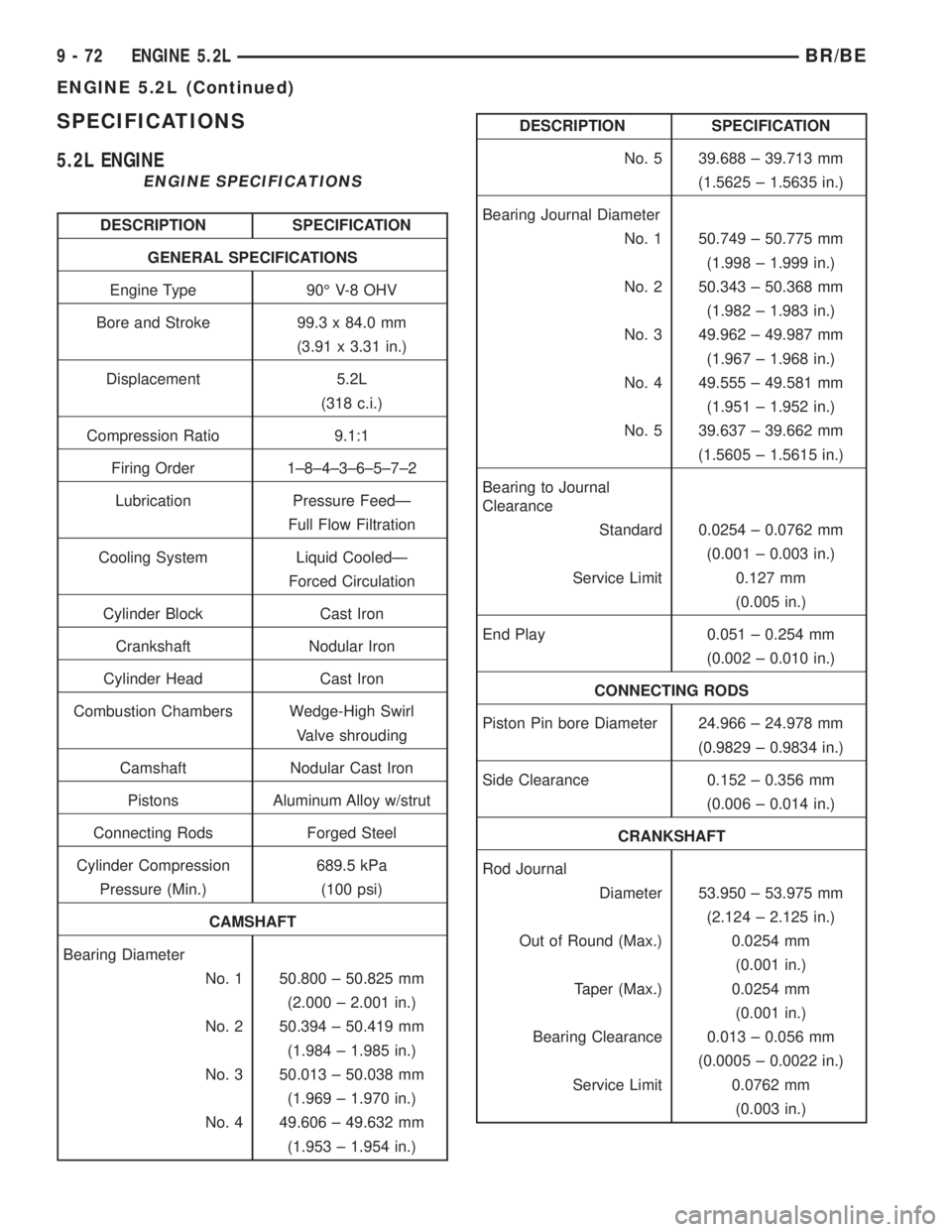
SPECIFICATIONS
5.2L ENGINE
ENGINE SPECIFICATIONS
DESCRIPTION SPECIFICATION
GENERAL SPECIFICATIONS
Engine Type 90É V-8 OHV
Bore and Stroke 99.3 x 84.0 mm
(3.91 x 3.31 in.)
Displacement 5.2L
(318 c.i.)
Compression Ratio 9.1:1
Firing Order 1±8±4±3±6±5±7±2
Lubrication Pressure FeedÐ
Full Flow Filtration
Cooling System Liquid CooledÐ
Forced Circulation
Cylinder Block Cast Iron
Crankshaft Nodular Iron
Cylinder Head Cast Iron
Combustion Chambers Wedge-High Swirl
Valve shrouding
Camshaft Nodular Cast Iron
Pistons Aluminum Alloy w/strut
Connecting Rods Forged Steel
Cylinder Compression 689.5 kPa
Pressure (Min.) (100 psi)
CAMSHAFT
Bearing Diameter
No. 1 50.800 ± 50.825 mm
(2.000 ± 2.001 in.)
No. 2 50.394 ± 50.419 mm
(1.984 ± 1.985 in.)
No. 3 50.013 ± 50.038 mm
(1.969 ± 1.970 in.)
No. 4 49.606 ± 49.632 mm
(1.953 ± 1.954 in.)
DESCRIPTION SPECIFICATION
No. 5 39.688 ± 39.713 mm
(1.5625 ± 1.5635 in.)
Bearing Journal Diameter
No. 1 50.749 ± 50.775 mm
(1.998 ± 1.999 in.)
No. 2 50.343 ± 50.368 mm
(1.982 ± 1.983 in.)
No. 3 49.962 ± 49.987 mm
(1.967 ± 1.968 in.)
No. 4 49.555 ± 49.581 mm
(1.951 ± 1.952 in.)
No. 5 39.637 ± 39.662 mm
(1.5605 ± 1.5615 in.)
Bearing to Journal
Clearance
Standard 0.0254 ± 0.0762 mm
(0.001 ± 0.003 in.)
Service Limit 0.127 mm
(0.005 in.)
End Play 0.051 ± 0.254 mm
(0.002 ± 0.010 in.)
CONNECTING RODS
Piston Pin bore Diameter 24.966 ± 24.978 mm
(0.9829 ± 0.9834 in.)
Side Clearance 0.152 ± 0.356 mm
(0.006 ± 0.014 in.)
CRANKSHAFT
Rod Journal
Diameter 53.950 ± 53.975 mm
(2.124 ± 2.125 in.)
Out of Round (Max.) 0.0254 mm
(0.001 in.)
Taper (Max.) 0.0254 mm
(0.001 in.)
Bearing Clearance 0.013 ± 0.056 mm
(0.0005 ± 0.0022 in.)
Service Limit 0.0762 mm
(0.003 in.)
9 - 72 ENGINE 5.2LBR/BE
ENGINE 5.2L (Continued)
Page 1222 of 2889
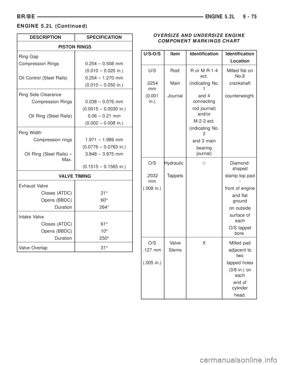
DESCRIPTION SPECIFICATION
PISTON RINGS
Ring Gap
Compression Rings 0.254 ± 0.508 mm
(0.010 ± 0.020 in.)
Oil Control (Steel Rails) 0.254 ± 1.270 mm
(0.010 ± 0.050 in.)
Ring Side Clearance
Compression Rings 0.038 ± 0.076 mm
(0.0015 ± 0.0030 in.)
Oil Ring (Steel Rails) 0.06 ± 0.21 mm
(0.002 ± 0.008 in.)
Ring Width
Compression rings 1.971 ± 1.989 mm
(0.0776 ± 0.0783 in.)
Oil Ring (Steel Rails) ±
Max.3.848 ± 3.975 mm
(0.1515 ± 0.1565 in.)
VALVE TIMING
Exhaust Valve
Closes (ATDC) 21É
Opens (BBDC) 60É
Duration 264É
Intake Valve
Closes (ATDC) 61É
Opens (BBDC) 10É
Duration 250É
Valve Overlap 31ÉOVERSIZE AND UNDERSIZE ENGINE
COMPONENT MARKINGS CHART
U/S-O/S Item Identification Identification
Location
U/S Rod/ R or M R-1-4
ect.Milled flat on
No.8
.0254
mmMain (indicating No.
1crankshaft
(0.001
in.)Journal and 4
connectingcounterweight.
rod journal)
and/or
M-2-3 ect.
(indicating No.
2
and 3 main
bearing
journal)
O/S HydraulicLDiamond-
shaped
.2032
mmTappets stamp top pad
-
(.008 in.) front of engine
and flat
ground
on outside
surface of
each
O/S tappet
bore.
O/S Valve X Milled pad
.127 mm Stems adjacent to
two
(.005 in.) tapped holes
(3/8 in.) on
each
end of
cylinder
head.
BR/BEENGINE 5.2L 9 - 75
ENGINE 5.2L (Continued)
Page 1226 of 2889
CYLINDER HEAD
DESCRIPTIONÐCYLINDER HEAD
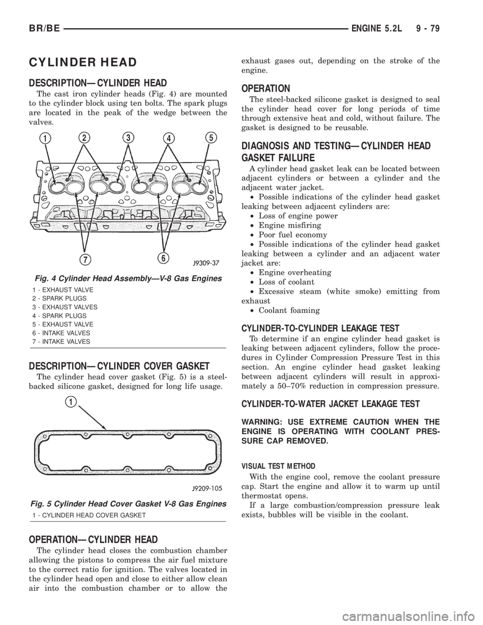
The cast iron cylinder heads (Fig. 4) are mounted
to the cylinder block using ten bolts. The spark plugs
are located in the peak of the wedge between the
valves.
DESCRIPTIONÐCYLINDER COVER GASKET
The cylinder head cover gasket (Fig. 5) is a steel-
backed silicone gasket, designed for long life usage.
OPERATIONÐCYLINDER HEAD
The cylinder head closes the combustion chamber
allowing the pistons to compress the air fuel mixture
to the correct ratio for ignition. The valves located in
the cylinder head open and close to either allow clean
air into the combustion chamber or to allow theexhaust gases out, depending on the stroke of the
engine.
OPERATION
The steel-backed silicone gasket is designed to seal
the cylinder head cover for long periods of time
through extensive heat and cold, without failure. The
gasket is designed to be reusable.
DIAGNOSIS AND TESTINGÐCYLINDER HEAD
GASKET FAILURE
A cylinder head gasket leak can be located between
adjacent cylinders or between a cylinder and the
adjacent water jacket.
²Possible indications of the cylinder head gasket
leaking between adjacent cylinders are:
²Loss of engine power
²Engine misfiring
²Poor fuel economy
²Possible indications of the cylinder head gasket
leaking between a cylinder and an adjacent water
jacket are:
²Engine overheating
²Loss of coolant
²Excessive steam (white smoke) emitting from
exhaust
²Coolant foaming
CYLINDER-TO-CYLINDER LEAKAGE TEST
To determine if an engine cylinder head gasket is
leaking between adjacent cylinders, follow the proce-
dures in Cylinder Compression Pressure Test in this
section. An engine cylinder head gasket leaking
between adjacent cylinders will result in approxi-
mately a 50±70% reduction in compression pressure.
CYLINDER-TO-WATER JACKET LEAKAGE TEST
WARNING: USE EXTREME CAUTION WHEN THE
ENGINE IS OPERATING WITH COOLANT PRES-
SURE CAP REMOVED.
VISUAL TEST METHOD
With the engine cool, remove the coolant pressure
cap. Start the engine and allow it to warm up until
thermostat opens.
If a large combustion/compression pressure leak
exists, bubbles will be visible in the coolant.
Fig. 4 Cylinder Head AssemblyÐV-8 Gas Engines
1 - EXHAUST VALVE
2 - SPARK PLUGS
3 - EXHAUST VALVES
4 - SPARK PLUGS
5 - EXHAUST VALVE
6 - INTAKE VALVES
7 - INTAKE VALVES
Fig. 5 Cylinder Head Cover Gasket V-8 Gas Engines
1 - CYLINDER HEAD COVER GASKET
BR/BEENGINE 5.2L 9 - 79
Page 1244 of 2889
PISTON & CONNECTING ROD
DESCRIPTION
The pistons are made of aluminum and have three
ring grooves, the top two grooves are for the compres-
sion rings and the bottom groove is for the oil control
ring. The connecting rods are forged steel and are
coined prior to heat treat. The piston pins are press
fit.
STANDARD PROCEDUREÐPISTON FITTING
Check the cylinder block bore for out-of-round,
taper, scoring, or scuffing.
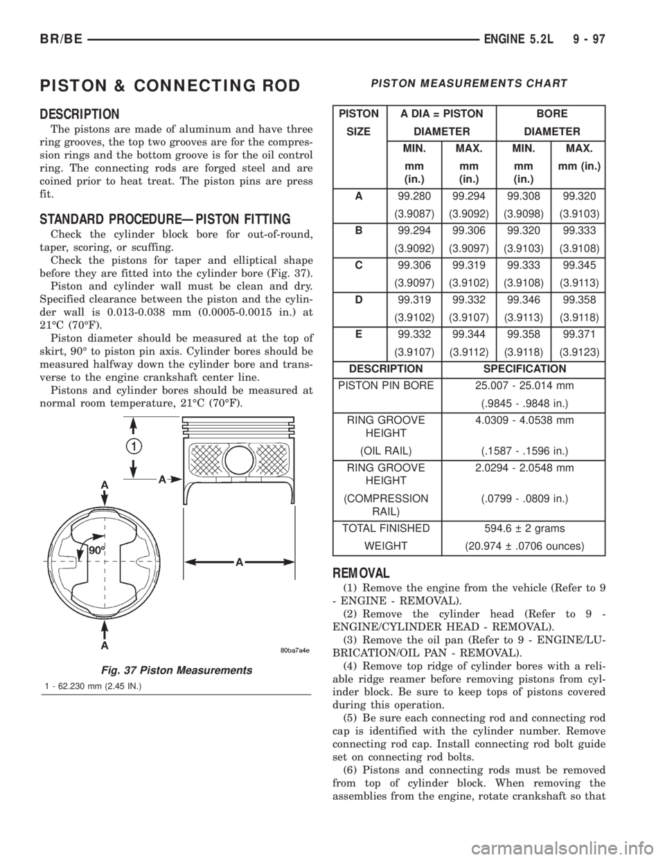
Check the pistons for taper and elliptical shape
before they are fitted into the cylinder bore (Fig. 37).
Piston and cylinder wall must be clean and dry.
Specified clearance between the piston and the cylin-
der wall is 0.013-0.038 mm (0.0005-0.0015 in.) at
21ÉC (70ÉF).
Piston diameter should be measured at the top of
skirt, 90É to piston pin axis. Cylinder bores should be
measured halfway down the cylinder bore and trans-
verse to the engine crankshaft center line.
Pistons and cylinder bores should be measured at
normal room temperature, 21ÉC (70ÉF).
PISTON MEASUREMENTS CHART
PISTON A DIA = PISTON BORE
SIZE DIAMETER DIAMETER
MIN. MAX. MIN. MAX.
mm
(in.)mm
(in.)mm
(in.)mm (in.)
A99.280 99.294 99.308 99.320
(3.9087) (3.9092) (3.9098) (3.9103)
B99.294 99.306 99.320 99.333
(3.9092) (3.9097) (3.9103) (3.9108)
C99.306 99.319 99.333 99.345
(3.9097) (3.9102) (3.9108) (3.9113)
D99.319 99.332 99.346 99.358
(3.9102) (3.9107) (3.9113) (3.9118)
E99.332 99.344 99.358 99.371
(3.9107) (3.9112) (3.9118) (3.9123)
DESCRIPTION SPECIFICATION
PISTON PIN BORE 25.007 - 25.014 mm
(.9845 - .9848 in.)
RING GROOVE
HEIGHT4.0309 - 4.0538 mm
(OIL RAIL) (.1587 - .1596 in.)
RING GROOVE
HEIGHT2.0294 - 2.0548 mm
(COMPRESSION
RAIL)(.0799 - .0809 in.)
TOTAL FINISHED 594.6 2 grams
WEIGHT (20.974 .0706 ounces)
REMOVAL
(1) Remove the engine from the vehicle (Refer to 9
- ENGINE - REMOVAL).
(2) Remove the cylinder head (Refer to 9 -
ENGINE/CYLINDER HEAD - REMOVAL).
(3) Remove the oil pan (Refer to 9 - ENGINE/LU-
BRICATION/OIL PAN - REMOVAL).
(4) Remove top ridge of cylinder bores with a reli-
able ridge reamer before removing pistons from cyl-
inder block. Be sure to keep tops of pistons covered
during this operation.
(5) Be sure each connecting rod and connecting rod
cap is identified with the cylinder number. Remove
connecting rod cap. Install connecting rod bolt guide
set on connecting rod bolts.
(6) Pistons and connecting rods must be removed
from top of cylinder block. When removing the
assemblies from the engine, rotate crankshaft so that
Fig. 37 Piston Measurements
1 - 62.230 mm (2.45 IN.)
BR/BEENGINE 5.2L 9 - 97