2001 DODGE RAM compression ratio
[x] Cancel search: compression ratioPage 1245 of 2889
the connecting rod is centered in cylinder bore and at
BDC.Be careful not to nick crankshaft journals.
(7) After removal, install bearing cap on the mat-
ing rod.
CLEANING
Clean the piston and connecting rod assembly
using a suitable solvent.
INSPECTION
Check the connecting rod journal for excessive
wear, taper and scoring (Refer to 9 - ENGINE/EN-
GINE BLOCK/CONNECTING ROD BEARINGS -
STANDARD PROCEDURE).
Check the connecting rod for signs of twist or bend-
ing.
Check the piston for taper and elliptical shape
before it is fitted into the cylinder bore (Refer to 9 -
ENGINE/ENGINE BLOCK/PISTON & CONNECT-
ING ROD - STANDARD PROCEDURE).
Check the piston for scoring, or scraping marks in
the piston skirts. Check the ring lands for cracks
and/or deterioration.
INSTALLATION
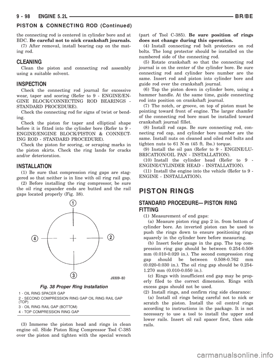
(1) Be sure that compression ring gaps are stag-
gered so that neither is in line with oil ring rail gap.
(2) Before installing the ring compressor, be sure
the oil ring expander ends are butted and the rail
gaps located properly (Fig. 38).
(3) Immerse the piston head and rings in clean
engine oil. Slide Piston Ring Compressor Tool C-385
over the piston and tighten with the special wrench(part of Tool C-385).Be sure position of rings
does not change during this operation.
(4) Install connecting rod bolt protectors on rod
bolts. The long protector should be installed on the
numbered side of the connecting rod.
(5) Rotate crankshaft so that the connecting rod
journal is on the center of the cylinder bore. Be sure
connecting rod and cylinder bore number are the
same. Insert rod and piston into cylinder bore and
guide rod over the crankshaft journal.
(6) Tap the piston down in cylinder bore, using a
hammer handle. At the same time, guide connecting
rod into position on crankshaft journal.
(7) The notch, or groove, on top of piston must be
pointing toward front of engine. The larger chamfer
of the connecting rod bore must be installed toward
crankshaft journal fillet.
(8) Install rod caps. Be sure connecting rod, con-
necting rod cap, and cylinder bore number are the
same. Install nuts on cleaned and oiled rod bolts and
tighten nuts to 61 N´m (45 ft. lbs.) torque.
(9) Install the oil pan (Refer to 9 - ENGINE/LU-
BRICATION/OIL PAN - INSTALLATION).
(10) Install the cylinder head (Refer to 9 -
ENGINE/CYLINDER HEAD - INSTALLATION).
(11) Install the engine into the vehicle (Refer to 9 -
ENGINE - INSTALLATION).
PISTON RINGS
STANDARD PROCEDUREÐPISTON RING
FITTING
(1) Measurement of end gaps:
(a) Measure piston ring gap 2 in. from bottom of
cylinder bore. An inverted piston can be used to
push the rings down to ensure positioning rings
squarely in the cylinder bore before measuring.
(b) Insert feeler gauge in the gap. The top com-
pression ring gap should be between 0.254-0.508
mm (0.010-0.020 in.). The second compression ring
gap should be between 0.508-0.762 mm
(0.020-0.030 in.). The oil ring gap should be 0.254-
1.270 mm (0.010-0.050 in.).
(c) Rings with insufficient end gap may be prop-
erly filed to the correct dimension. Rings with
excess gaps should not be used.
(2) Install rings, and confirm ring side clearance:
(a) Install oil rings being careful not to nick or
scratch the piston. Install the oil control rings
according to instructions in the package. It is not
necessary to use a tool to install the upper and
lower rails. Insert oil rail spacer first, then side
rails.
Fig. 38 Proper Ring Installation
1 - OIL RING SPACER GAP
2 - SECOND COMPRESSION RING GAP OIL RING RAIL GAP
(TOP)
3 - OIL RING RAIL GAP (BOTTOM)
4 - TOP COMPRESSION RING GAP
9 - 98 ENGINE 5.2LBR/BE
PISTON & CONNECTING ROD (Continued)
Page 1246 of 2889
(b) Install the second compression rings using
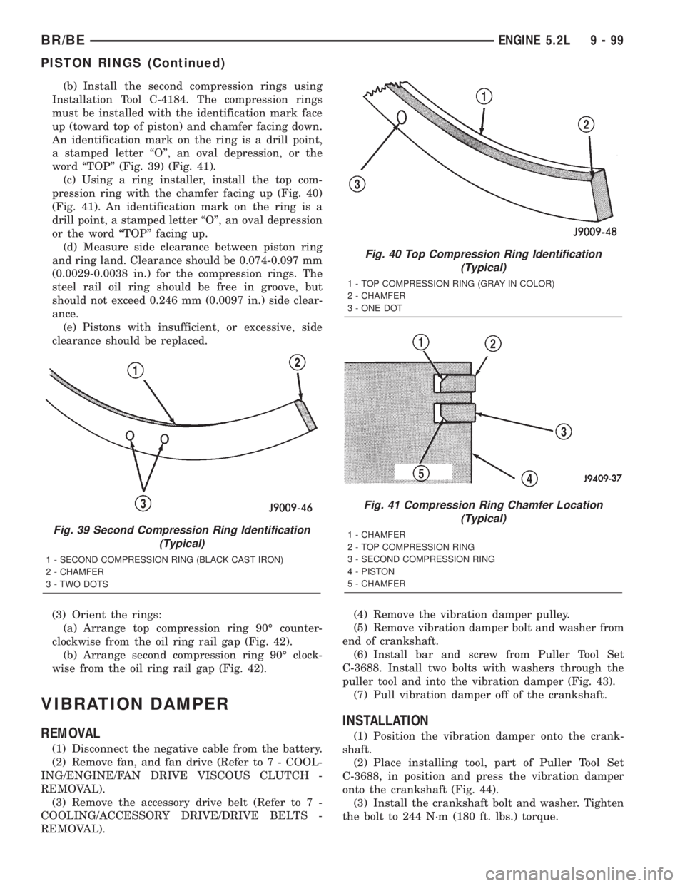
Installation Tool C-4184. The compression rings
must be installed with the identification mark face
up (toward top of piston) and chamfer facing down.
An identification mark on the ring is a drill point,
a stamped letter ªOº, an oval depression, or the
word ªTOPº (Fig. 39) (Fig. 41).
(c) Using a ring installer, install the top com-
pression ring with the chamfer facing up (Fig. 40)
(Fig. 41). An identification mark on the ring is a
drill point, a stamped letter ªOº, an oval depression
or the word ªTOPº facing up.
(d) Measure side clearance between piston ring
and ring land. Clearance should be 0.074-0.097 mm
(0.0029-0.0038 in.) for the compression rings. The
steel rail oil ring should be free in groove, but
should not exceed 0.246 mm (0.0097 in.) side clear-
ance.
(e) Pistons with insufficient, or excessive, side
clearance should be replaced.
(3) Orient the rings:
(a) Arrange top compression ring 90É counter-
clockwise from the oil ring rail gap (Fig. 42).
(b) Arrange second compression ring 90É clock-
wise from the oil ring rail gap (Fig. 42).
VIBRATION DAMPER
REMOVAL
(1) Disconnect the negative cable from the battery.
(2) Remove fan, and fan drive (Refer to 7 - COOL-
ING/ENGINE/FAN DRIVE VISCOUS CLUTCH -
REMOVAL).
(3) Remove the accessory drive belt (Refer to 7 -
COOLING/ACCESSORY DRIVE/DRIVE BELTS -
REMOVAL).(4) Remove the vibration damper pulley.
(5) Remove vibration damper bolt and washer from
end of crankshaft.
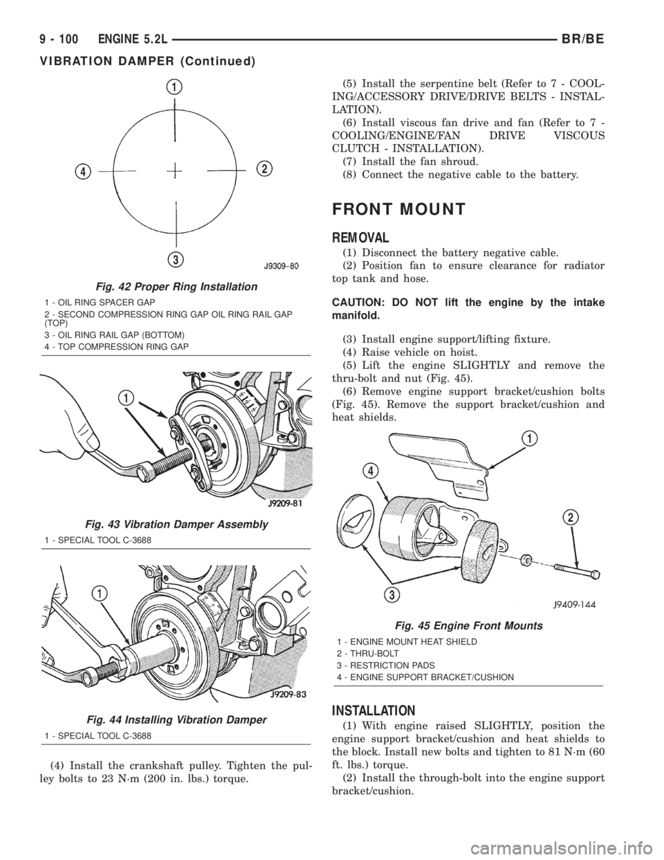
(6) Install bar and screw from Puller Tool Set
C-3688. Install two bolts with washers through the
puller tool and into the vibration damper (Fig. 43).
(7) Pull vibration damper off of the crankshaft.
INSTALLATION
(1) Position the vibration damper onto the crank-
shaft.
(2) Place installing tool, part of Puller Tool Set
C-3688, in position and press the vibration damper
onto the crankshaft (Fig. 44).
(3) Install the crankshaft bolt and washer. Tighten
the bolt to 244 N´m (180 ft. lbs.) torque.
Fig. 39 Second Compression Ring Identification
(Typical)
1 - SECOND COMPRESSION RING (BLACK CAST IRON)
2 - CHAMFER
3 - TWO DOTS
Fig. 40 Top Compression Ring Identification
(Typical)
1 - TOP COMPRESSION RING (GRAY IN COLOR)
2 - CHAMFER
3 - ONE DOT
Fig. 41 Compression Ring Chamfer Location
(Typical)
1 - CHAMFER
2 - TOP COMPRESSION RING
3 - SECOND COMPRESSION RING
4 - PISTON
5 - CHAMFER
BR/BEENGINE 5.2L 9 - 99
PISTON RINGS (Continued)
Page 1247 of 2889
(4) Install the crankshaft pulley. Tighten the pul-
ley bolts to 23 N´m (200 in. lbs.) torque.(5) Install the serpentine belt (Refer to 7 - COOL-
ING/ACCESSORY DRIVE/DRIVE BELTS - INSTAL-
LATION).
(6) Install viscous fan drive and fan (Refer to 7 -
COOLING/ENGINE/FAN DRIVE VISCOUS
CLUTCH - INSTALLATION).
(7) Install the fan shroud.
(8) Connect the negative cable to the battery.
FRONT MOUNT
REMOVAL
(1) Disconnect the battery negative cable.
(2) Position fan to ensure clearance for radiator
top tank and hose.
CAUTION: DO NOT lift the engine by the intake
manifold.
(3) Install engine support/lifting fixture.
(4) Raise vehicle on hoist.
(5) Lift the engine SLIGHTLY and remove the
thru-bolt and nut (Fig. 45).
(6) Remove engine support bracket/cushion bolts
(Fig. 45). Remove the support bracket/cushion and
heat shields.
INSTALLATION
(1) With engine raised SLIGHTLY, position the
engine support bracket/cushion and heat shields to
the block. Install new bolts and tighten to 81 N´m (60
ft. lbs.) torque.
(2) Install the through-bolt into the engine support
bracket/cushion.
Fig. 42 Proper Ring Installation
1 - OIL RING SPACER GAP
2 - SECOND COMPRESSION RING GAP OIL RING RAIL GAP
(TOP)
3 - OIL RING RAIL GAP (BOTTOM)
4 - TOP COMPRESSION RING GAP
Fig. 43 Vibration Damper Assembly
1 - SPECIAL TOOL C-3688
Fig. 44 Installing Vibration Damper
1 - SPECIAL TOOL C-3688
Fig. 45 Engine Front Mounts
1 - ENGINE MOUNT HEAT SHIELD
2 - THRU-BOLT
3 - RESTRICTION PADS
4 - ENGINE SUPPORT BRACKET/CUSHION
9 - 100 ENGINE 5.2LBR/BE
VIBRATION DAMPER (Continued)
Page 1263 of 2889
ENGINE 5.9L
TABLE OF CONTENTS
page page
ENGINE 5.9L
DESCRIPTION..........................117
DIAGNOSIS AND TESTING................118
ENGINE DIAGNOSIS - INTRODUCTION.....118
PERFORMANCE.......................118
MECHANICAL.........................120
LUBRICATION........................123
CYLINDER COMPRESSION PRESSURE....124
CYLINDER COMBUSTION PRESSURE
LEAKAGE............................124
STANDARD PROCEDURE.................125
FORM-IN-PLACE GASKETS AND SEALERS . . 125
REPAIR DAMAGED OR WORN THREADS . . . 125
HYDROSTATIC LOCK...................125
CYLINDER BORE HONING...............126
REMOVAL.............................126
INSTALLATION..........................127
SPECIFICATIONS........................129
SPECIAL TOOLS........................134
CYLINDER HEAD
DESCRIPTION..........................136
OPERATION............................136
DIAGNOSIS AND TESTING................136
CYLINDER HEAD GASKET FAILURE.......136
REMOVAL.............................137
CLEANING.............................137
INSPECTION...........................137
INSTALLATION..........................137
CYLINDER HEAD COVER(S)
REMOVAL.............................138
CLEANING.............................138
INSPECTION...........................138
INSTALLATION..........................138
INTAKE/EXHAUST VALVES & SEATS
DESCRIPTION..........................138
STANDARD PROCEDURE.................138
VALVES, GUIDES AND SPRINGS..........138
REMOVAL.............................140
CLEANING.............................140
INSPECTION...........................141
INSTALLATION..........................141
ROCKER ARM / ADJUSTER ASSY
REMOVAL.............................142
INSTALLATION..........................142
ENGINE BLOCK
CLEANING.............................142
INSPECTION...........................142
CAMSHAFT & BEARINGS (IN BLOCK)
REMOVAL.............................143INSTALLATION..........................144
CONNECTING ROD BEARINGS
STANDARD PROCEDURE.................144
CONNECTING ROD BEARING FITTING.....144
CRANKSHAFT
DESCRIPTION..........................145
OPERATION............................145
REMOVAL.............................145
INSTALLATION..........................145
CRANKSHAFT MAIN BEARINGS
DESCRIPTION..........................146
OPERATION............................146
STANDARD PROCEDURE.................146
CRANKSHAFT MAIN BEARING FITTING....146
REMOVAL.............................147
INSTALLATION..........................147
CRANKSHAFT OIL SEAL - FRONT
DESCRIPTION..........................147
OPERATION............................147
REMOVAL.............................147
INSTALLATION..........................148
CRANKSHAFT OIL SEAL - REAR
DESCRIPTION..........................148
OPERATION............................148
REMOVAL.............................149
INSTALLATION..........................149
DISTRIBUTOR BUSHING
REMOVAL.............................150
INSTALLATION..........................150
HYDRAULIC LIFTERS
DIAGNOSIS AND TESTING................151
HYDRAULIC TAPPETS..................151
REMOVAL.............................152
CLEANING.............................152
INSTALLATION..........................152
PISTON & CONNECTING ROD
DESCRIPTION..........................153
STANDARD PROCEDURE.................153
PISTON FITTING......................153
REMOVAL.............................154
CLEANING.............................154
INSPECTION...........................154
INSTALLATION..........................154
PISTON RINGS
STANDARD PROCEDURE.................154
PISTON RING FITTING..................154
VIBRATION DAMPER
REMOVAL.............................155
INSTALLATION..........................156
9 - 116 ENGINE 5.9LBR/BE
Page 1276 of 2889
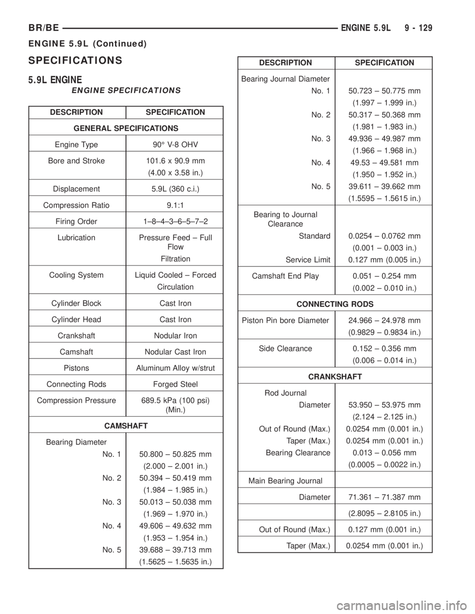
SPECIFICATIONS
5.9L ENGINE
ENGINE SPECIFICATIONS
DESCRIPTION SPECIFICATION
GENERAL SPECIFICATIONS
Engine Type 90É V-8 OHV
Bore and Stroke 101.6 x 90.9 mm
(4.00 x 3.58 in.)
Displacement 5.9L (360 c.i.)
Compression Ratio 9.1:1
Firing Order 1±8±4±3±6±5±7±2
Lubrication Pressure Feed ± Full
Flow
Filtration
Cooling System Liquid Cooled ± Forced
Circulation
Cylinder Block Cast Iron
Cylinder Head Cast Iron
Crankshaft Nodular Iron
Camshaft Nodular Cast Iron
Pistons Aluminum Alloy w/strut
Connecting Rods Forged Steel
Compression Pressure 689.5 kPa (100 psi)
(Min.)
CAMSHAFT
Bearing Diameter
No. 1 50.800 ± 50.825 mm
(2.000 ± 2.001 in.)
No. 2 50.394 ± 50.419 mm
(1.984 ± 1.985 in.)
No. 3 50.013 ± 50.038 mm
(1.969 ± 1.970 in.)
No. 4 49.606 ± 49.632 mm
(1.953 ± 1.954 in.)
No. 5 39.688 ± 39.713 mm
(1.5625 ± 1.5635 in.)
DESCRIPTION SPECIFICATION
Bearing Journal Diameter
No. 1 50.723 ± 50.775 mm
(1.997 ± 1.999 in.)
No. 2 50.317 ± 50.368 mm
(1.981 ± 1.983 in.)
No. 3 49.936 ± 49.987 mm
(1.966 ± 1.968 in.)
No. 4 49.53 ± 49.581 mm
(1.950 ± 1.952 in.)
No. 5 39.611 ± 39.662 mm
(1.5595 ± 1.5615 in.)
Bearing to Journal
Clearance
Standard 0.0254 ± 0.0762 mm
(0.001 ± 0.003 in.)
Service Limit 0.127 mm (0.005 in.)
Camshaft End Play 0.051 ± 0.254 mm
(0.002 ± 0.010 in.)
CONNECTING RODS
Piston Pin bore Diameter 24.966 ± 24.978 mm
(0.9829 ± 0.9834 in.)
Side Clearance 0.152 ± 0.356 mm
(0.006 ± 0.014 in.)
CRANKSHAFT
Rod Journal
Diameter 53.950 ± 53.975 mm
(2.124 ± 2.125 in.)
Out of Round (Max.) 0.0254 mm (0.001 in.)
Taper (Max.) 0.0254 mm (0.001 in.)
Bearing Clearance 0.013 ± 0.056 mm
(0.0005 ± 0.0022 in.)
Main Bearing Journal
Diameter 71.361 ± 71.387 mm
(2.8095 ± 2.8105 in.)
Out of Round (Max.) 0.127 mm (0.001 in.)
Taper (Max.) 0.0254 mm (0.001 in.)
BR/BEENGINE 5.9L 9 - 129
ENGINE 5.9L (Continued)
Page 1283 of 2889
CYLINDER HEAD
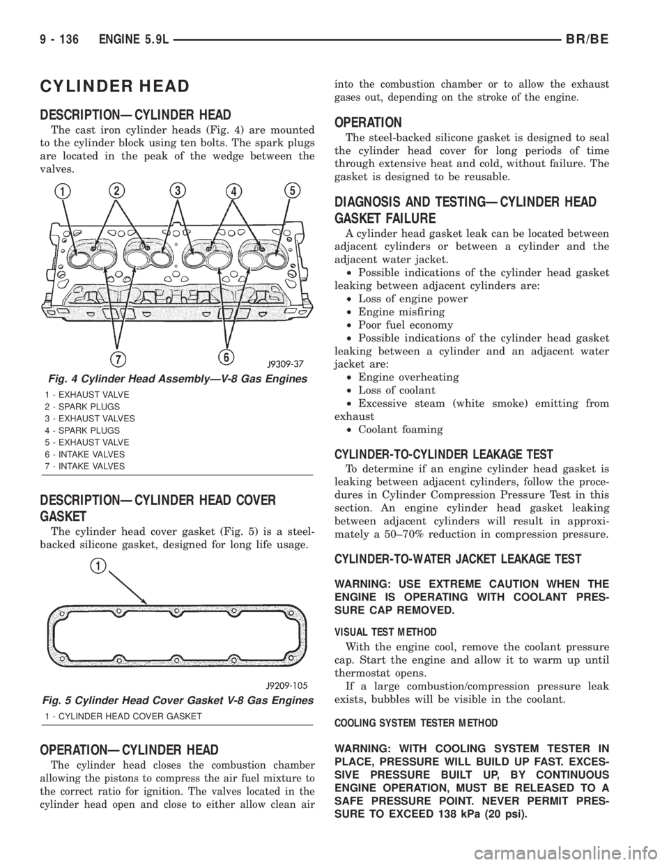
DESCRIPTIONÐCYLINDER HEAD
The cast iron cylinder heads (Fig. 4) are mounted
to the cylinder block using ten bolts. The spark plugs
are located in the peak of the wedge between the
valves.
DESCRIPTIONÐCYLINDER HEAD COVER
GASKET
The cylinder head cover gasket (Fig. 5) is a steel-
backed silicone gasket, designed for long life usage.
OPERATIONÐCYLINDER HEAD
The cylinder head closes the combustion chamber
allowing the pistons to compress the air fuel mixture to
the correct ratio for ignition. The valves located in the
cylinder head open and close to either allow clean airinto the combustion chamber or to allow the exhaust
gases out, depending on the stroke of the engine.
OPERATION
The steel-backed silicone gasket is designed to seal
the cylinder head cover for long periods of time
through extensive heat and cold, without failure. The
gasket is designed to be reusable.
DIAGNOSIS AND TESTINGÐCYLINDER HEAD
GASKET FAILURE
A cylinder head gasket leak can be located between
adjacent cylinders or between a cylinder and the
adjacent water jacket.
²Possible indications of the cylinder head gasket
leaking between adjacent cylinders are:
²Loss of engine power
²Engine misfiring
²Poor fuel economy
²Possible indications of the cylinder head gasket
leaking between a cylinder and an adjacent water
jacket are:
²Engine overheating
²Loss of coolant
²Excessive steam (white smoke) emitting from
exhaust
²Coolant foaming
CYLINDER-TO-CYLINDER LEAKAGE TEST
To determine if an engine cylinder head gasket is
leaking between adjacent cylinders, follow the proce-
dures in Cylinder Compression Pressure Test in this
section. An engine cylinder head gasket leaking
between adjacent cylinders will result in approxi-
mately a 50±70% reduction in compression pressure.
CYLINDER-TO-WATER JACKET LEAKAGE TEST
WARNING: USE EXTREME CAUTION WHEN THE
ENGINE IS OPERATING WITH COOLANT PRES-
SURE CAP REMOVED.
VISUAL TEST METHOD
With the engine cool, remove the coolant pressure
cap. Start the engine and allow it to warm up until
thermostat opens.
If a large combustion/compression pressure leak
exists, bubbles will be visible in the coolant.
COOLING SYSTEM TESTER METHOD
WARNING: WITH COOLING SYSTEM TESTER IN
PLACE, PRESSURE WILL BUILD UP FAST. EXCES-
SIVE PRESSURE BUILT UP, BY CONTINUOUS
ENGINE OPERATION, MUST BE RELEASED TO A
SAFE PRESSURE POINT. NEVER PERMIT PRES-
SURE TO EXCEED 138 kPa (20 psi).
Fig. 4 Cylinder Head AssemblyÐV-8 Gas Engines
1 - EXHAUST VALVE
2 - SPARK PLUGS
3 - EXHAUST VALVES
4 - SPARK PLUGS
5 - EXHAUST VALVE
6 - INTAKE VALVES
7 - INTAKE VALVES
Fig. 5 Cylinder Head Cover Gasket V-8 Gas Engines
1 - CYLINDER HEAD COVER GASKET
9 - 136 ENGINE 5.9LBR/BE
Page 1301 of 2889
REMOVAL
(1) Remove the engine from the vehicle (Refer to 9
- ENGINE - REMOVAL).
(2) Remove the cylinder head (Refer to 9 -
ENGINE/CYLINDER HEAD - REMOVAL).
(3) Remove the oil pan (Refer to 9 - ENGINE/LU-
BRICATION/OIL PAN - REMOVAL).
(4) Remove top ridge of cylinder bores with a reli-
able ridge reamer before removing pistons from cyl-
inder block. Be sure to keep tops of pistons covered
during this operation.
(5) Be sure each connecting rod and connecting rod
cap is identified with the cylinder number. Remove
connecting rod cap. Install connecting rod bolt guide
set on connecting rod bolts.
(6) Pistons and connecting rods must be removed
from top of cylinder block. When removing the
assemblies from the engine, rotate crankshaft so that
the connecting rod is centered in cylinder bore and at
BDC.Be careful not to nick crankshaft journals.
(7) After removal, install bearing cap on the mat-
ing rod.
CLEANING
Clean the piston and connecting rod assembly
using a suitable solvent.
INSPECTION
Check the connecting rod journal for excessive
wear, taper and scoring (Refer to 9 - ENGINE/EN-
GINE BLOCK/CONNECTING ROD BEARINGS -
STANDARD PROCEDURE).
Check the connecting rod for signs of twist or bend-
ing.
Check the piston for taper and elliptical shape
before it is fitted into the cylinder bore (Refer to 9 -
ENGINE/ENGINE BLOCK/PISTON & CONNECT-
ING ROD - STANDARD PROCEDURE).
Check the piston for scoring, or scraping marks in
the piston skirts. Check the ring lands for cracks
and/or deterioration.
INSTALLATION
(1) Be sure that compression ring gaps are stag-
gered so that neither is in line with oil ring rail gap.
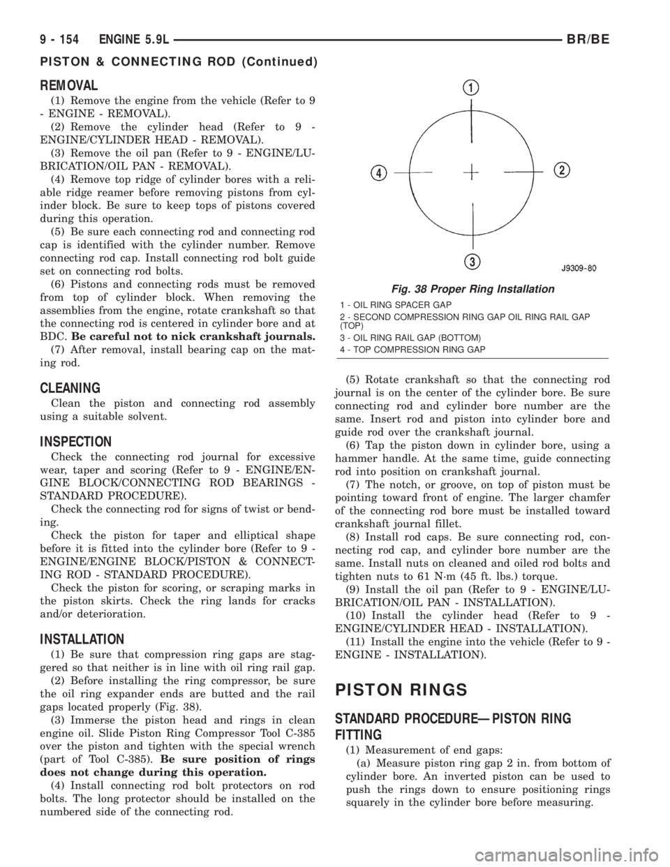
(2) Before installing the ring compressor, be sure
the oil ring expander ends are butted and the rail
gaps located properly (Fig. 38).
(3) Immerse the piston head and rings in clean
engine oil. Slide Piston Ring Compressor Tool C-385
over the piston and tighten with the special wrench
(part of Tool C-385).Be sure position of rings
does not change during this operation.
(4) Install connecting rod bolt protectors on rod
bolts. The long protector should be installed on the
numbered side of the connecting rod.(5) Rotate crankshaft so that the connecting rod
journal is on the center of the cylinder bore. Be sure
connecting rod and cylinder bore number are the
same. Insert rod and piston into cylinder bore and
guide rod over the crankshaft journal.
(6) Tap the piston down in cylinder bore, using a
hammer handle. At the same time, guide connecting
rod into position on crankshaft journal.
(7) The notch, or groove, on top of piston must be
pointing toward front of engine. The larger chamfer
of the connecting rod bore must be installed toward
crankshaft journal fillet.
(8) Install rod caps. Be sure connecting rod, con-
necting rod cap, and cylinder bore number are the
same. Install nuts on cleaned and oiled rod bolts and
tighten nuts to 61 N´m (45 ft. lbs.) torque.
(9) Install the oil pan (Refer to 9 - ENGINE/LU-
BRICATION/OIL PAN - INSTALLATION).
(10) Install the cylinder head (Refer to 9 -
ENGINE/CYLINDER HEAD - INSTALLATION).
(11) Install the engine into the vehicle (Refer to 9 -
ENGINE - INSTALLATION).
PISTON RINGS
STANDARD PROCEDUREÐPISTON RING
FITTING
(1) Measurement of end gaps:
(a) Measure piston ring gap 2 in. from bottom of
cylinder bore. An inverted piston can be used to
push the rings down to ensure positioning rings
squarely in the cylinder bore before measuring.
Fig. 38 Proper Ring Installation
1 - OIL RING SPACER GAP
2 - SECOND COMPRESSION RING GAP OIL RING RAIL GAP
(TOP)
3 - OIL RING RAIL GAP (BOTTOM)
4 - TOP COMPRESSION RING GAP
9 - 154 ENGINE 5.9LBR/BE
PISTON & CONNECTING ROD (Continued)
Page 1302 of 2889
(b) Insert feeler gauge in the gap. The top com-
pression ring gap should be between 0.254-0.508
mm (0.010-0.020 in.). The second compression ring
gap should be between 0.508-0.762 mm
(0.020-0.030 in.). The oil ring gap should be 0.254-
1.270 mm (0.010-0.050 in.).
(c) Rings with insufficient end gap may be prop-
erly filed to the correct dimension. Rings with
excess gaps should not be used.
(2) Install rings, and confirm ring side clearance:
(a)
Install oil rings being careful not to nick or
scratch the piston. Install the oil control rings accord-
ing to instructions in the package. It is not necessary
to use a tool to install the upper and lower rails.
Insert oil rail spacer first, then side rails.
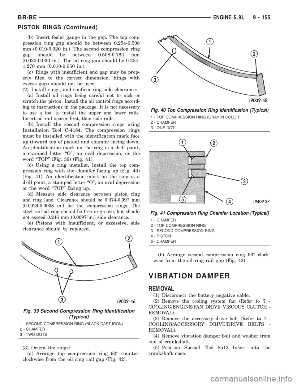
(b) Install the second compression rings using
Installation Tool C-4184. The compression rings
must be installed with the identification mark face
up (toward top of piston) and chamfer facing down.
An identification mark on the ring is a drill point,
a stamped letter ªOº, an oval depression, or the
word ªTOPº (Fig. 39) (Fig. 41).
(c) Using a ring installer, install the top com-
pression ring with the chamfer facing up (Fig. 40)
(Fig. 41). An identification mark on the ring is a
drill point, a stamped letter ªOº, an oval depression
or the word ªTOPº facing up.
(d)
Measure side clearance between piston ring
and ring land. Clearance should be 0.074-0.097 mm
(0.0029-0.0038 in.) for the compression rings. The
steel rail oil ring should be free in groove, but should
not exceed 0.246 mm (0.0097 in.) side clearance.
(e) Pistons with insufficient, or excessive, side
clearance should be replaced.
(3) Orient the rings:
(a) Arrange top compression ring 90É counter-
clockwise from the oil ring rail gap (Fig. 42).(b) Arrange second compression ring 90É clock-
wise from the oil ring rail gap (Fig. 42) .
VIBRATION DAMPER
REMOVAL
(1) Disconnect the battery negative cable.
(2)
Remove the cooling system fan (Refer to 7 -
COOLING/ENGINE/FAN DRIVE VISCOUS CLUTCH -
REMOVAL).
(3) Remove the accessory drive belt (Refer to 7 -
COOLING/ACCESSORY DRIVE/DRIVE BELTS -
REMOVAL).
(4) Remove vibration damper bolt and washer from
end of crankshaft.
(5) Position Special Tool 8513 Insert into the
crankshaft nose.
Fig. 39 Second Compression Ring Identification
(Typical)
1 - SECOND COMPRESSION RING (BLACK CAST IRON)
2 - CHAMFER
3 - TWO DOTS
Fig. 40 Top Compression Ring Identification (Typical)
1 - TOP COMPRESSION RING (GRAY IN COLOR)
2 - CHAMFER
3 - ONE DOT
Fig. 41 Compression Ring Chamfer Location (Typical)
1 - CHAMFER
2 - TOP COMPRESSION RING
3 - SECOND COMPRESSION RING
4 - PISTON
5 - CHAMFER
BR/BEENGINE 5.9L 9 - 155
PISTON RINGS (Continued)