2001 DODGE RAM spare tire
[x] Cancel search: spare tirePage 1141 of 2889
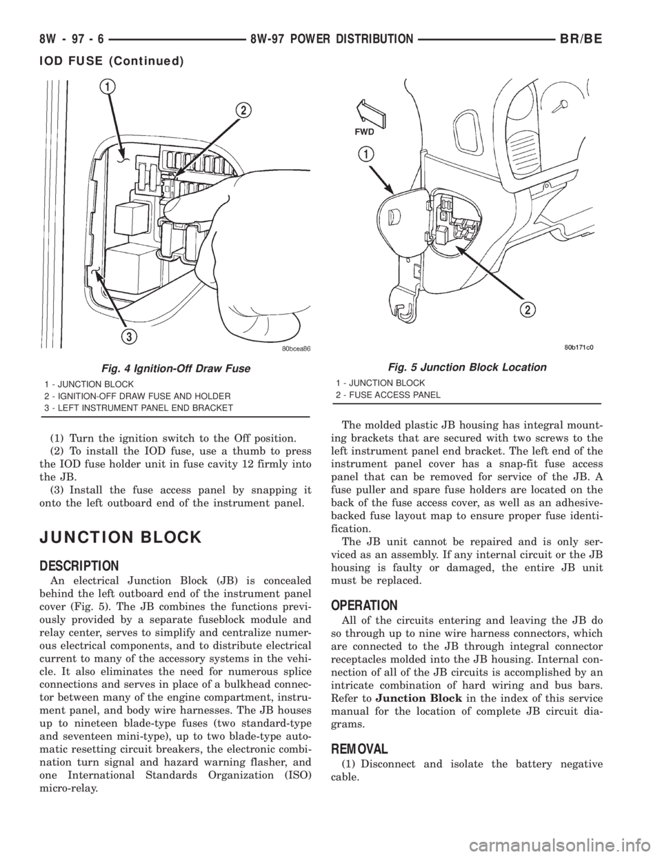
(1) Turn the ignition switch to the Off position.
(2) To install the IOD fuse, use a thumb to press
the IOD fuse holder unit in fuse cavity 12 firmly into
the JB.
(3) Install the fuse access panel by snapping it
onto the left outboard end of the instrument panel.
JUNCTION BLOCK
DESCRIPTION
An electrical Junction Block (JB) is concealed
behind the left outboard end of the instrument panel
cover (Fig. 5). The JB combines the functions previ-
ously provided by a separate fuseblock module and
relay center, serves to simplify and centralize numer-
ous electrical components, and to distribute electrical
current to many of the accessory systems in the vehi-
cle. It also eliminates the need for numerous splice
connections and serves in place of a bulkhead connec-
tor between many of the engine compartment, instru-
ment panel, and body wire harnesses. The JB houses
up to nineteen blade-type fuses (two standard-type
and seventeen mini-type), up to two blade-type auto-
matic resetting circuit breakers, the electronic combi-
nation turn signal and hazard warning flasher, and
one International Standards Organization (ISO)
micro-relay.The molded plastic JB housing has integral mount-
ing brackets that are secured with two screws to the
left instrument panel end bracket. The left end of the
instrument panel cover has a snap-fit fuse access
panel that can be removed for service of the JB. A
fuse puller and spare fuse holders are located on the
back of the fuse access cover, as well as an adhesive-
backed fuse layout map to ensure proper fuse identi-
fication.
The JB unit cannot be repaired and is only ser-
viced as an assembly. If any internal circuit or the JB
housing is faulty or damaged, the entire JB unit
must be replaced.
OPERATION
All of the circuits entering and leaving the JB do
so through up to nine wire harness connectors, which
are connected to the JB through integral connector
receptacles molded into the JB housing. Internal con-
nection of all of the JB circuits is accomplished by an
intricate combination of hard wiring and bus bars.
Refer toJunction Blockin the index of this service
manual for the location of complete JB circuit dia-
grams.
REMOVAL
(1) Disconnect and isolate the battery negative
cable.
Fig. 4 Ignition-Off Draw Fuse
1 - JUNCTION BLOCK
2 - IGNITION-OFF DRAW FUSE AND HOLDER
3 - LEFT INSTRUMENT PANEL END BRACKET
Fig. 5 Junction Block Location
1 - JUNCTION BLOCK
2 - FUSE ACCESS PANEL
8W - 97 - 6 8W-97 POWER DISTRIBUTIONBR/BE
IOD FUSE (Continued)
Page 1476 of 2889
FRAME & BUMPERS
TABLE OF CONTENTS
page page
BUMPERS
DESCRIPTION............................1
FRONT AIR DAM
REMOVAL...............................1
INSTALLATION............................2
FRONT FASCIA
REMOVAL...............................2
INSTALLATION............................2
ADJUSTMENT............................2
FRONT LOWER FASCIA
REMOVAL...............................3
INSTALLATION............................3
FRONT FASCIAÐSPORT
REMOVAL...............................3
INSTALLATION............................3
FRONT BUMPER
REMOVAL...............................3
INSTALLATION............................4
FRONT BUMPERÐSPORT
REMOVAL...............................4
INSTALLATION............................4REAR BUMPER
REMOVAL...............................5
INSTALLATION............................5
FRAME
DESCRIPTION............................6
SPECIFICATIONS.........................7
CAB CHASSIS ADAPTER BRACKET
REMOVAL...............................9
INSTALLATION............................9
FRONT TOW HOOK
REMOVAL...............................9
INSTALLATION...........................10
SPARE TIRE WINCH
REMOVAL..............................10
INSTALLATION...........................10
TRAILER HITCH
REMOVAL..............................10
INSTALLATION...........................10
TRANSFER CASE SKID PLATE
REMOVAL..............................11
INSTALLATION...........................11
BUMPERS
DESCRIPTION
Bumpers are used at the front and rear of the
vehicle. Bumpers may be chrome or painted.
Bumpers are designed to protect the exterior sheet-
metal in low impact situations. The bumpers are
attached to the frame and provide mounting points
for some optional accessories such as fog lights and
tow hooks.
FRONT AIR DAM
REMOVAL
(1) Remove Pin-type fasteners attaching air dam
to bottom of front bumper (Fig. 1).
(2) Remove screws attaching air dam to bottom of
front bumper.
(3) Separate air dam from bumper.
BR/BEFRAME & BUMPERS 13 - 1
Page 1484 of 2889
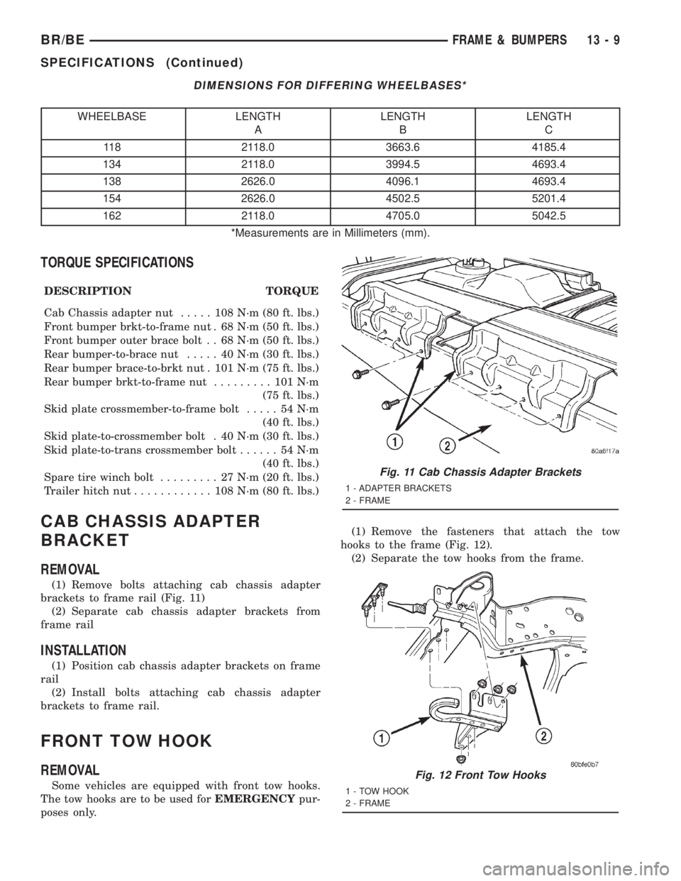
DIMENSIONS FOR DIFFERING WHEELBASES*
WHEELBASE LENGTH
ALENGTH
BLENGTH
C
118 2118.0 3663.6 4185.4
134 2118.0 3994.5 4693.4
138 2626.0 4096.1 4693.4
154 2626.0 4502.5 5201.4
162 2118.0 4705.0 5042.5
*Measurements are in Millimeters (mm).
TORQUE SPECIFICATIONS
DESCRIPTION TORQUE
Cab Chassis adapter nut..... 108N´m(80ft.lbs.)
Front bumper brkt-to-frame nut . 68 N´m (50 ft. lbs.)
Front bumper outer brace bolt . . 68 N´m (50 ft. lbs.)
Rear bumper-to-brace nut..... 40N´m(30ft.lbs.)
Rear bumper brace-to-brkt nut . 101 N´m (75 ft. lbs.)
Rear bumper brkt-to-frame nut......... 101N´m
(75 ft. lbs.)
Skid plate crossmember-to-frame bolt..... 54N´m
(40 ft. lbs.)
Skid plate-to-crossmember bolt . 40 N´m (30 ft. lbs.)
Skid plate-to-trans crossmember bolt...... 54N´m
(40 ft. lbs.)
Spare tire winch bolt......... 27N´m(20ft.lbs.)
Trailer hitch nut............ 108N´m(80ft.lbs.)
CAB CHASSIS ADAPTER
BRACKET
REMOVAL
(1) Remove bolts attaching cab chassis adapter
brackets to frame rail (Fig. 11)
(2) Separate cab chassis adapter brackets from
frame rail
INSTALLATION
(1) Position cab chassis adapter brackets on frame
rail
(2) Install bolts attaching cab chassis adapter
brackets to frame rail.
FRONT TOW HOOK
REMOVAL
Some vehicles are equipped with front tow hooks.
The tow hooks are to be used forEMERGENCYpur-
poses only.(1) Remove the fasteners that attach the tow
hooks to the frame (Fig. 12).
(2) Separate the tow hooks from the frame.
Fig. 11 Cab Chassis Adapter Brackets
1 - ADAPTER BRACKETS
2 - FRAME
Fig. 12 Front Tow Hooks
1 - TOW HOOK
2 - FRAME
BR/BEFRAME & BUMPERS 13 - 9
SPECIFICATIONS (Continued)
Page 1485 of 2889
Installation
Some vehicles are equipped with front tow hooks.
The tow hooks are to be used forEMERGENCYpur-
poses only.
(1) Position the tow hooks on the frame.
(2) Install the fasteners that attach the tow hooks
to the frame.
(3) Tighten the nuts to 108 N´m (80 ft. lbs.) torque.
SPARE TIRE WINCH
REMOVAL
(1) Remove spare tire from under vehicle.
(2) Remove cotter pin attaching winch tube to
spare tire winch.
(3) Pull winch tube from spare tire winch.
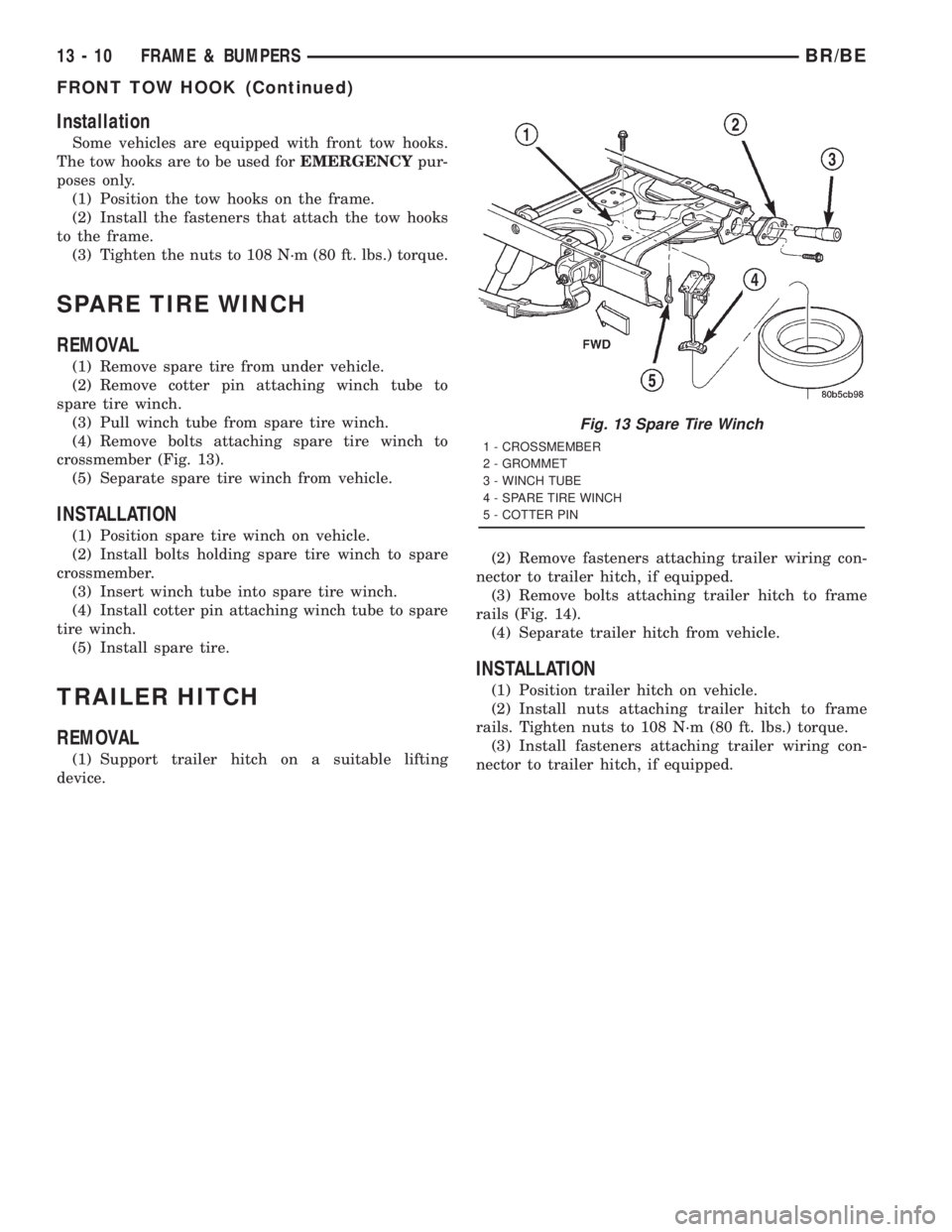
(4) Remove bolts attaching spare tire winch to
crossmember (Fig. 13).
(5) Separate spare tire winch from vehicle.
INSTALLATION
(1) Position spare tire winch on vehicle.
(2) Install bolts holding spare tire winch to spare
crossmember.
(3) Insert winch tube into spare tire winch.
(4) Install cotter pin attaching winch tube to spare
tire winch.
(5) Install spare tire.
TRAILER HITCH
REMOVAL
(1) Support trailer hitch on a suitable lifting
device.(2) Remove fasteners attaching trailer wiring con-
nector to trailer hitch, if equipped.
(3) Remove bolts attaching trailer hitch to frame
rails (Fig. 14).
(4) Separate trailer hitch from vehicle.
INSTALLATION
(1) Position trailer hitch on vehicle.
(2) Install nuts attaching trailer hitch to frame
rails. Tighten nuts to 108 N´m (80 ft. lbs.) torque.
(3) Install fasteners attaching trailer wiring con-
nector to trailer hitch, if equipped.
Fig. 13 Spare Tire Winch
1 - CROSSMEMBER
2 - GROMMET
3 - WINCH TUBE
4 - SPARE TIRE WINCH
5 - COTTER PIN
13 - 10 FRAME & BUMPERSBR/BE
FRONT TOW HOOK (Continued)
Page 1486 of 2889
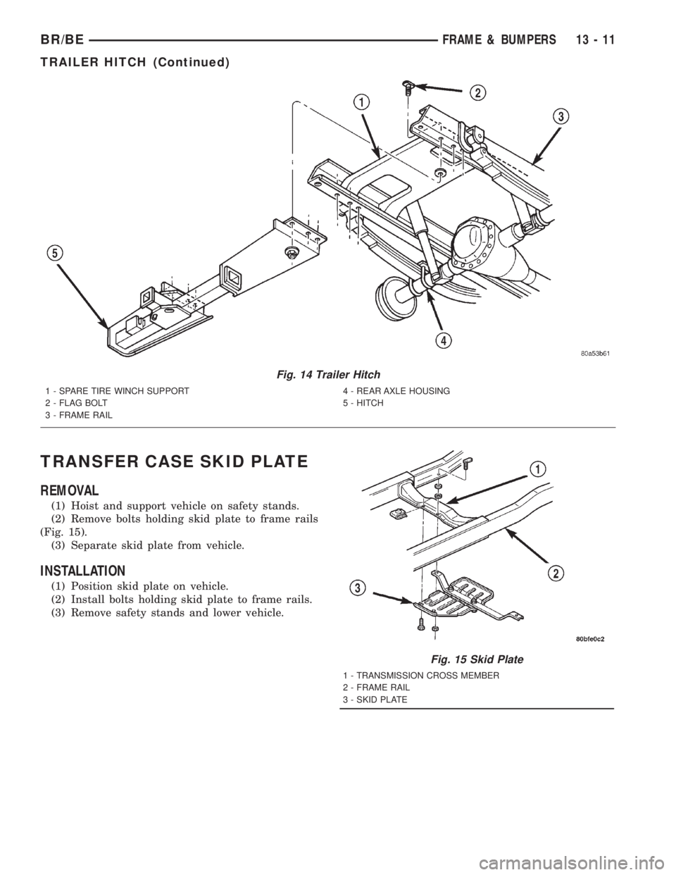
TRANSFER CASE SKID PLATE
REMOVAL
(1) Hoist and support vehicle on safety stands.
(2) Remove bolts holding skid plate to frame rails
(Fig. 15).
(3) Separate skid plate from vehicle.
INSTALLATION
(1) Position skid plate on vehicle.
(2) Install bolts holding skid plate to frame rails.
(3) Remove safety stands and lower vehicle.
Fig. 14 Trailer Hitch
1 - SPARE TIRE WINCH SUPPORT
2 - FLAG BOLT
3 - FRAME RAIL4 - REAR AXLE HOUSING
5 - HITCH
Fig. 15 Skid Plate
1 - TRANSMISSION CROSS MEMBER
2 - FRAME RAIL
3 - SKID PLATE
BR/BEFRAME & BUMPERS 13 - 11
TRAILER HITCH (Continued)
Page 2562 of 2889
TIRES/WHEELS
TABLE OF CONTENTS
page page
TIRES/WHEELS
DIAGNOSIS AND TESTING..................1
TIRE AND WHEEL RUNOUT...............1
STANDARD PROCEDURE...................2
TIRE ROTATION.........................2
MATCH MOUNTING......................2
TIRE AND WHEEL BALANCE...............4
TIRES
DESCRIPTION............................5
DIAGNOSIS AND TESTING..................7
PRESSURE GAUGES....................7
TREAD WEAR INDICATORS...............7
TIRE WEAR PATTERNS...................7
TIRE NOISE OR VIBRATION...............8
STANDARD PROCEDURE...................8
REPAIRING LEAKS......................8
SPECIFICATIONS.........................9SPARE TIRE
DESCRIPTION............................9
WHEELS
DESCRIPTION............................9
OPERATION.............................10
DIAGNOSIS AND TESTING.................10
WHEEL INSPECTION....................10
STANDARD PROCEDURE..................10
DUAL WHEEL INSTALLATION.............10
SPECIFICATIONS.........................11
STUDS
REMOVAL..............................12
INSTALLATION...........................12
WHEEL COVER
REMOVAL..............................12
INSTALLATION...........................12
TIRES/WHEELS
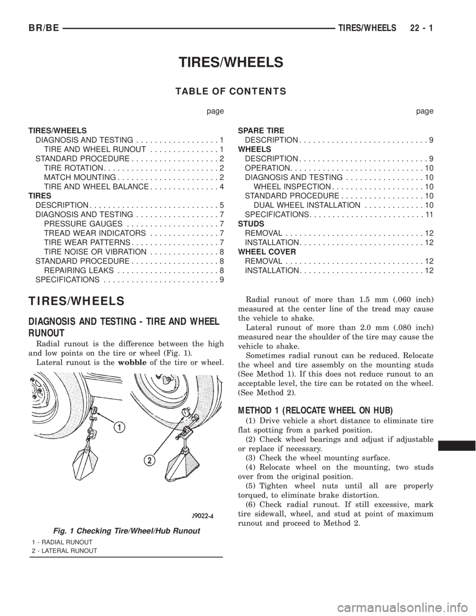
DIAGNOSIS AND TESTING - TIRE AND WHEEL
RUNOUT
Radial runout is the difference between the high
and low points on the tire or wheel (Fig. 1).
Lateral runout is thewobbleof the tire or wheel.Radial runout of more than 1.5 mm (.060 inch)
measured at the center line of the tread may cause
the vehicle to shake.
Lateral runout of more than 2.0 mm (.080 inch)
measured near the shoulder of the tire may cause the
vehicle to shake.
Sometimes radial runout can be reduced. Relocate
the wheel and tire assembly on the mounting studs
(See Method 1). If this does not reduce runout to an
acceptable level, the tire can be rotated on the wheel.
(See Method 2).
METHOD 1 (RELOCATE WHEEL ON HUB)
(1) Drive vehicle a short distance to eliminate tire
flat spotting from a parked position.
(2) Check wheel bearings and adjust if adjustable
or replace if necessary.
(3) Check the wheel mounting surface.
(4) Relocate wheel on the mounting, two studs
over from the original position.
(5) Tighten wheel nuts until all are properly
torqued, to eliminate brake distortion.
(6) Check radial runout. If still excessive, mark
tire sidewall, wheel, and stud at point of maximum
runout and proceed to Method 2.
Fig. 1 Checking Tire/Wheel/Hub Runout
1 - RADIAL RUNOUT
2 - LATERAL RUNOUT
BR/BETIRES/WHEELS 22 - 1
Page 2566 of 2889
TIRES
DESCRIPTION
The temporary spare tire is designed for emer-
gency use only. The original tire should be repaired
or replaced at the first opportunity, then reinstalled.
Do not exceed speeds of 50 M.P.H. when using the
temporary spare tire. Refer to Owner's Manual for
complete details.
DESCRIPTION
Tires are designed and engineered for each specific
vehicle. They provide the best overall performance
for normal operation. The ride and handling charac-
teristics match the vehicle's requirements. With
proper care they will give excellent reliability, trac-
tion, skid resistance, and tread life.
Driving habits have more effect on tire life than
any other factor. Careful drivers will obtain in most
cases, much greater mileage than severe use or care-
less drivers. A few of the driving habits which will
shorten the life of any tire are:
²Rapid acceleration
²Severe brake applications
²High speed driving
²Excessive speeds on turns
²Striking curbs and other obstacles
Radial-ply tires are more prone to irregular tread
wear. It is important to follow the tire rotation inter-val shown in the section on Tire Rotation, (Refer to
22 - TIRES/WHEELS - STANDARD PROCEDURE).
This will help to achieve a greater tread life.
TIRE IDENTIFICATION
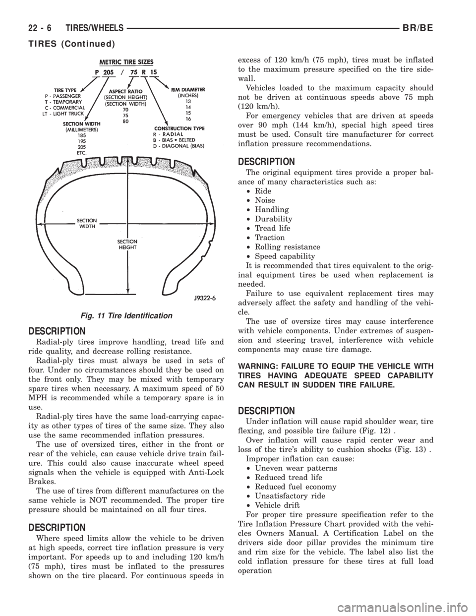
Tire type, size, aspect ratio and speed rating are
encoded in the letters and numbers imprinted on the
side wall of the tire. Refer to the chart to decipher
the tire identification code (Fig. 11).
Performance tires have a speed rating letter after
the aspect ratio number. The speed rating is not
always printed on the tire sidewall. These ratings
are:
²Qup to 100 mph
²Rup to 106 mph
²Sup to 112 mph
²Tup to 118 mph
²Uup to 124 mph
²Hup to 130 mph
²Vup to 149 mph
²Zmore than 149 mph (consult the tire manu-
facturer for the specific speed rating)
An All Season type tire will have eitherM+S,M
&SorM±S(indicating mud and snow traction)
imprinted on the side wall.
TIRE CHAINS
Tire snow chains may be used oncertainmodels.
Refer to the Owner's Manual for more information.
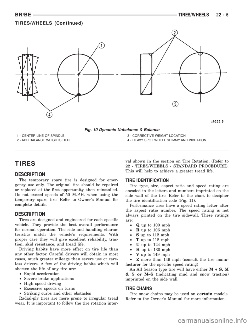
Fig. 10 Dynamic Unbalance & Balance
1 - CENTER LINE OF SPINDLE
2 - ADD BALANCE WEIGHTS HERE3 - CORRECTIVE WEIGHT LOCATION
4 - HEAVY SPOT WHEEL SHIMMY AND VIBRATION
BR/BETIRES/WHEELS 22 - 5
TIRES/WHEELS (Continued)
Page 2567 of 2889
DESCRIPTION
Radial-ply tires improve handling, tread life and
ride quality, and decrease rolling resistance.
Radial-ply tires must always be used in sets of
four. Under no circumstances should they be used on
the front only. They may be mixed with temporary
spare tires when necessary. A maximum speed of 50
MPH is recommended while a temporary spare is in
use.
Radial-ply tires have the same load-carrying capac-
ity as other types of tires of the same size. They also
use the same recommended inflation pressures.
The use of oversized tires, either in the front or
rear of the vehicle, can cause vehicle drive train fail-
ure. This could also cause inaccurate wheel speed
signals when the vehicle is equipped with Anti-Lock
Brakes.
The use of tires from different manufactures on the
same vehicle is NOT recommended. The proper tire
pressure should be maintained on all four tires.
DESCRIPTION
Where speed limits allow the vehicle to be driven
at high speeds, correct tire inflation pressure is very
important. For speeds up to and including 120 km/h
(75 mph), tires must be inflated to the pressures
shown on the tire placard. For continuous speeds inexcess of 120 km/h (75 mph), tires must be inflated
to the maximum pressure specified on the tire side-
wall.
Vehicles loaded to the maximum capacity should
not be driven at continuous speeds above 75 mph
(120 km/h).
For emergency vehicles that are driven at speeds
over 90 mph (144 km/h), special high speed tires
must be used. Consult tire manufacturer for correct
inflation pressure recommendations.
DESCRIPTION
The original equipment tires provide a proper bal-
ance of many characteristics such as:
²Ride
²Noise
²Handling
²Durability
²Tread life
²Traction
²Rolling resistance
²Speed capability
It is recommended that tires equivalent to the orig-
inal equipment tires be used when replacement is
needed.
Failure to use equivalent replacement tires may
adversely affect the safety and handling of the vehi-
cle.
The use of oversize tires may cause interference
with vehicle components. Under extremes of suspen-
sion and steering travel, interference with vehicle
components may cause tire damage.
WARNING: FAILURE TO EQUIP THE VEHICLE WITH
TIRES HAVING ADEQUATE SPEED CAPABILITY
CAN RESULT IN SUDDEN TIRE FAILURE.
DESCRIPTION
Under inflation will cause rapid shoulder wear, tire
flexing, and possible tire failure (Fig. 12) .
Over inflation will cause rapid center wear and
loss of the tire's ability to cushion shocks (Fig. 13) .
Improper inflation can cause:
²Uneven wear patterns
²Reduced tread life
²Reduced fuel economy
²Unsatisfactory ride
²Vehicle drift
For proper tire pressure specification refer to the
Tire Inflation Pressure Chart provided with the vehi-
cles Owners Manual. A Certification Label on the
drivers side door pillar provides the minimum tire
and rim size for the vehicle. The label also list the
cold inflation pressure for these tires at full load
operation
Fig. 11 Tire Identification
22 - 6 TIRES/WHEELSBR/BE
TIRES (Continued)