2001 DODGE RAM fog light
[x] Cancel search: fog lightPage 7 of 2889

FASTENER USAGE
DESCRIPTION - FASTENER USAGE
WARNING: USE OF AN INCORRECT FASTENER
MAY RESULT IN COMPONENT DAMAGE OR PER-
SONAL INJURY.
Figure art, specifications and torque references in
this Service Manual are identified in metric and SAE
format.
During any maintenance or repair procedures, it is
important to salvage all fasteners (nuts, bolts, etc.)
for reassembly. If the fastener is not salvageable, a
fastener of equivalent specification must be used.
DESCRIPTION - THREADED HOLE REPAIR
Most stripped threaded holes can be repaired using
a Helicoilt. Follow the manufactures recommenda-
tions for application and repair procedures.
INTERNATIONAL VEHICLE
CONTROL & DISPLAY
SYMBOLS
DESCRIPTION - INTERNATIONAL SYMBOLS
The graphic symbols illustrated in the following
International Control and Display Symbols Chart are
used to identify various instrument controls. The
symbols correspond to the controls and displays that
are located on the instrument panel.
METRIC SYSTEM
DESCRIPTION - METRIC SYSTEM
The metric system is based on quantities of one,
ten, one hundred, one thousand and one million .
The following chart will assist in converting metric
units to equivalent English and SAE units, or vise
versa.
International Symbols
1 High Beam 13 Rear Window Washer
2 Fog Lamps 14 Fuel
3 Headlamp, Parking Lamps, Panel Lamps 15 Engine Coolant Temperature
4 Turn Warning 16 Battery Charging Condition
5 Hazard Warning 17 Engine Oil
6 Windshield Washer 18 Seat Belt
7 Windshield Wiper 19 Brake Failure
8 Windshield Wiper and Washer 20 Parking Brake
9 Windscreen Demisting and Defrosting 21 Front Hood
10 Ventilating Fan 22 Rear hood (Decklid)
11 Rear Window Defogger 23 Horn
12 Rear Window Wiper 24 Lighter
6 INTRODUCTIONBR/BE
Page 519 of 2889
(3) Disconnect and isolate the battery negative
cable. Disconnect the 3-way instrument panel wire
harness connector for the heated mirror switch from
the heated mirror switch connector receptacle on the
back of the a/c heater control. Check for continuity
between the ground circuit cavity of the wire harness
connector and a good ground. There should be conti-
nuity. If OK, go to Step 4. If not OK, repair the open
ground circuit to ground as required.
(4) Reconnect the battery negative cable. Turn the
ignition switch to the On position. Check for battery
voltage at the fused ignition switch output (run/start)
circuit cavity of the 3-way instrument panel wire
harness connector for the heated mirror switch. If
OK, go to Step 5. If not OK, repair the open fused
ignition switch output (run/start) circuit to the fuse
in the JB as required.
(5) Turn the ignition switch to the Off position.
Disconnect and isolate the battery negative cable.
Reconnect the 3-way instrument panel wire harness
connector for the heated mirror switch to the heated
mirror switch connector receptacle on the back of the
a/c heater control. Reconnect the battery negative
cable. Turn the ignition switch to the On position.
Depress and release the heated mirror switch. The
amber heated mirror system indicator lamp next to
the heated mirror switch button should light. If OK,
go to Step 6. If not OK, replace the faulty a/c heater
control.
(6) Back probe the fused heated mirror relay out-
put circuit cavity of the 3-way instrument panel wire
harness connector for the heated mirror switch on
the back of the a/c heater control and check for volt-
age (battery voltage less the resistance in both out-
side mirror heating grids). If OK, (Refer to 8 -
ELECTRICAL/HEATED MIRRORS/HEATED MIR-
ROR GRID - DIAGNOSIS AND TESTING).
HEATED MIRROR GRID
DESCRIPTION
Vehicles equipped with the optional heated mirror
system have an electrically operated heating grid
located behind the mirror glass of each power oper-
ated outside rear view mirror. The outside mirror
heating grid consists of two thin laminations of plas-
tic that approximate the outer dimensions and shape
of the mirror glass. A single length of resistor wire
weaves in a back and forth pattern between, and is
held in place by the two thin laminations of plastic.
The two ends of the resistor wire terminate near the
inboard edge of the grid, where they are soldered to
the ground feed and battery current feed wires con-
tained in the power mirror wire harness. The heating
grid is then sandwiched between the back of themolded plastic mirror glass case and the mirror
glass, where it remains in direct contact with the
back of the mirror glass at all times.
The outside mirror heating grids cannot be
repaired and, if faulty or damaged, the entire outside
power mirror unit must be replaced. Refer to Power
Mirrors for the service procedures.
OPERATION
One end of the outside mirror heating grid resistor
wire is connected to a ground feed at all times
through a body ground screw located inside the left
rear corner of the truck cab. Battery current is
directed to the other end of the outside mirror heat-
ing grid resistor wire by the energized heated mirror
relay when the heated mirror switch is in the On
position. As electrical current passes through the
heating grid, the resistance of the wire in the heating
grid converts some of that electrical current into
heat. The heat produced by the heating grid is then
conducted through the back of the mirror glass to
help keep the glass clear of ice, snow or fog.
DIAGNOSIS AND TESTING - HEATED MIRROR
GRID
For circuit descriptions and diagrams (Refer to
Appropriate Wiring Information).
(1) Disconnect and isolate the battery negative
cable. Disconnect the door wire harness connector
from the power mirror wire harness connector at the
power mirror with the inoperative heating grid.
Check for continuity between the ground circuit cav-
ity in the door wire harness connector for the power
mirror and a good ground. If OK, go to Step 2. If not
OK, repair the open ground circuit to ground as
required.
(2) Reconnect the battery negative cable. Turn the
ignition switch to the On position. Turn on the
heated mirror system. Check for voltage (battery
voltage less the resistance in the outside mirror heat-
ing grid that is still connected) at the fused heated
mirror relay output circuit cavity in the door wire
harness connector for the power mirror. If OK, go to
Step 3. If not OK, repair the open fused heated mir-
ror relay output circuit to the heater and air condi-
tioner control unit as required.
(3) Check the outside mirror heating grid by test-
ing for continuity between the ground circuit and the
fused heated mirror relay output circuit cavities in
the power mirror wire harness connector. There
should be continuity. If not OK, replace the faulty
power mirror. If OK, check the resistance through
the outside mirror heating grid. The correct resis-
tance should be from 10 to 16 ohms when measured
at an ambient temperature of 21É C (70É F). If not
OK, replace the faulty power mirror.
8G - 4 HEATED MIRRORSBR/BE
MIRROR SWITCH (Continued)
Page 598 of 2889
LAMPS
TABLE OF CONTENTS
page page
LAMPS/LIGHTING - EXTERIOR............... 1LAMPS/LIGHTING - INTERIOR............... 33
LAMPS/LIGHTING - EXTERIOR
TABLE OF CONTENTS
page page
LAMPS/LIGHTING - EXTERIOR
DESCRIPTION............................2
OPERATION.............................2
DIAGNOSIS AND TESTING..................3
TURN SIGNAL & HAZARD WARNING
SYSTEM...............................3
SPECIFICATIONS.........................4
SPECIAL TOOLS..........................4
BRAKE LAMP SWITCH
DESCRIPTION............................4
OPERATION.............................4
DIAGNOSIS AND TESTING..................5
BRAKE LAMP SWITCH...................5
REMOVAL...............................5
INSTALLATION............................5
CENTER HIGH MOUNTED STOP LAMP
REMOVAL...............................6
INSTALLATION............................6
CENTER HIGH MOUNTED STOP LAMP UNIT
REMOVAL...............................6
INSTALLATION............................6
CLEARANCE LAMP
REMOVAL...............................6
INSTALLATION............................6
COMBINATION FLASHER
DESCRIPTION............................7
OPERATION.............................7
REMOVAL...............................8
INSTALLATION............................8
DAYTIME RUNNING LAMP MODULE
DESCRIPTION............................9
OPERATION.............................9
REMOVAL...............................9
INSTALLATION............................9
FOG LAMP
DIAGNOSIS AND TESTING..................9
FOG LAMP.............................9REMOVAL..............................11
INSTALLATION...........................11
FOG LAMP UNIT
REMOVAL..............................11
INSTALLATION...........................12
ADJUSTMENTS..........................12
HEADLAMP
DESCRIPTION...........................13
OPERATION.............................13
DIAGNOSIS AND TESTING.................13
HEADLAMP...........................13
REMOVAL..............................16
INSTALLATION...........................16
HEADLAMP RELAY
DESCRIPTION...........................16
OPERATION.............................17
DIAGNOSIS AND TESTING.................17
HEADLAMP RELAY.....................17
REMOVAL..............................18
INSTALLATION...........................18
HEADLAMP SWITCH
DESCRIPTION...........................18
OPERATION.............................18
DIAGNOSIS AND TESTING.................18
HEADLAMP SWITCH....................18
REMOVAL..............................19
INSTALLATION...........................20
HEADLAMP UNIT
REMOVAL..............................20
INSTALLATION...........................20
ADJUSTMENTS..........................21
LICENSE PLATE LAMP
REMOVAL..............................22
INSTALLATION...........................22
LICENSE PLATE LAMP UNIT
REMOVAL..............................22
INSTALLATION...........................22
BR/BELAMPS 8L - 1
Page 601 of 2889
(9) Disconnect the instrument panel wire harness
connector for the multi-function switch from the
switch connector receptacle. Check for continuity
between the hazard flasher signal circuit cavities in
the JB receptacle for the combination flasher and the
instrument panel wire harness connector for the
multi-function switch. There should be continuity. If
OK, go to Step 10. If not OK, repair the open hazard
flasher signal circuit between the JB and the multi-
function switch as required.
(10) Check for continuity between the flasher out-
put circuit cavities of the JB receptacle for the com-
bination flasher and in the instrument panel wire
harness connector for the multi-function switch.
There should be continuity. If OK, test the multi-
function switch. (Refer to 8 - ELECTRICAL/LAMPS/
LIGHTING - EXTERIOR/MULTI-FUNCTION
SWITCH - DIAGNOSIS AND TESTING). If not OK,
repair the open flasher output circuit between the JB
and the multi-function switch as required.
SPECIFICATIONS
EXTERIOR LAMPS
LAMP BULB
Back-up 3157
Cargo 921
Center High Mounted
Stop921
Clearance Roof Mounted 168
Fog Lamps 896
Headlamp - SLT 9004LL
Headlamp - Sport Low
Beam9007
Headlamp - Sport High
Beam9004LL
License Plate w/o
Bumper1155
License Plate -Step
Bumper168
Park/Turn Signal 3157NA
Snow Plow Control 161
Tail/Brake/Turn Signal 3157
Tail/Brake/Cab - Chassis 1157
Underhood 105
SPECIAL TOOLS
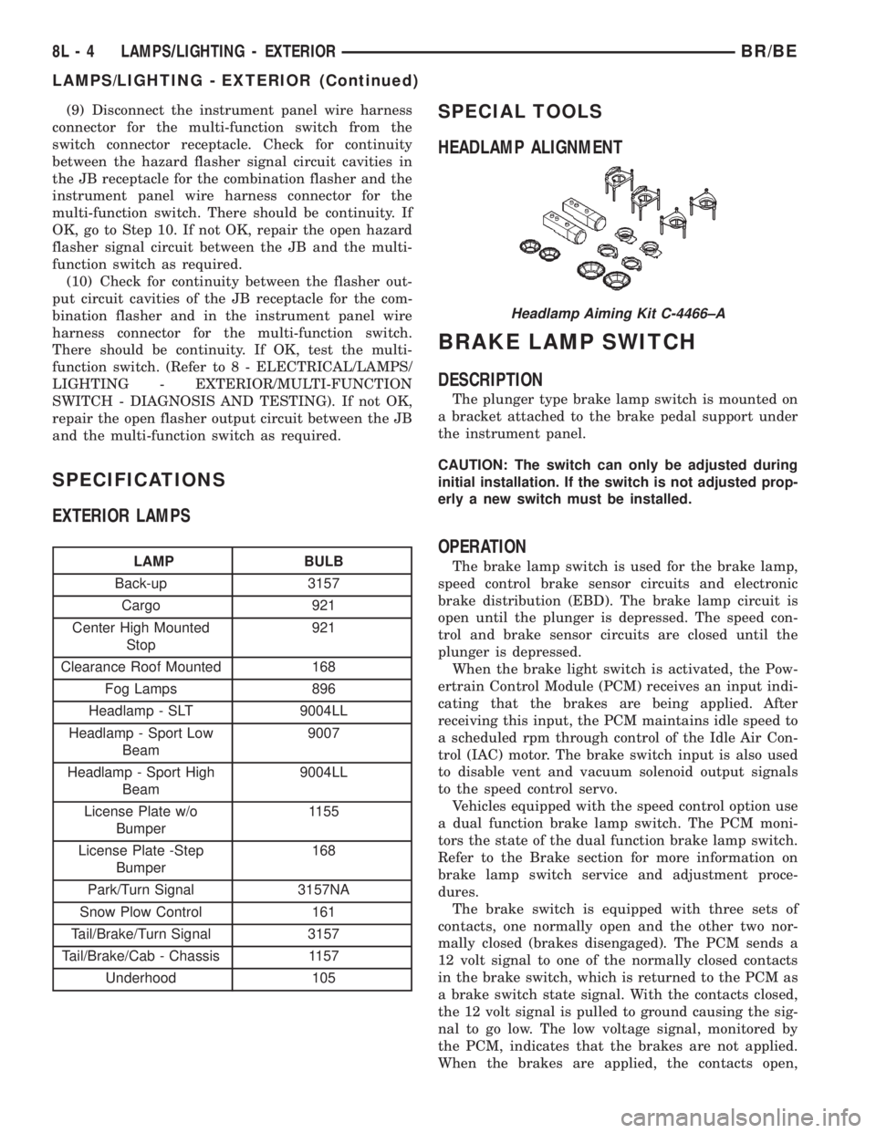
HEADLAMP ALIGNMENT
BRAKE LAMP SWITCH
DESCRIPTION
The plunger type brake lamp switch is mounted on
a bracket attached to the brake pedal support under
the instrument panel.
CAUTION: The switch can only be adjusted during
initial installation. If the switch is not adjusted prop-
erly a new switch must be installed.
OPERATION
The brake lamp switch is used for the brake lamp,
speed control brake sensor circuits and electronic
brake distribution (EBD). The brake lamp circuit is
open until the plunger is depressed. The speed con-
trol and brake sensor circuits are closed until the
plunger is depressed.
When the brake light switch is activated, the Pow-
ertrain Control Module (PCM) receives an input indi-
cating that the brakes are being applied. After
receiving this input, the PCM maintains idle speed to
a scheduled rpm through control of the Idle Air Con-
trol (IAC) motor. The brake switch input is also used
to disable vent and vacuum solenoid output signals
to the speed control servo.
Vehicles equipped with the speed control option use
a dual function brake lamp switch. The PCM moni-
tors the state of the dual function brake lamp switch.
Refer to the Brake section for more information on
brake lamp switch service and adjustment proce-
dures.
The brake switch is equipped with three sets of
contacts, one normally open and the other two nor-
mally closed (brakes disengaged). The PCM sends a
12 volt signal to one of the normally closed contacts
in the brake switch, which is returned to the PCM as
a brake switch state signal. With the contacts closed,
the 12 volt signal is pulled to ground causing the sig-
nal to go low. The low voltage signal, monitored by
the PCM, indicates that the brakes are not applied.
When the brakes are applied, the contacts open,
Headlamp Aiming Kit C-4466±A
8L - 4 LAMPS/LIGHTING - EXTERIORBR/BE
LAMPS/LIGHTING - EXTERIOR (Continued)
Page 606 of 2889
DAYTIME RUNNING LAMP
MODULE
DESCRIPTION
The Daytime Running Lights (Headlamps) System
is installed on vehicles manufactured for sale in Can-
ada only. A separate module, mounted on the cowl,
controls the DRL.
OPERATION
The headlamps are illuminated when the ignition
switch is turned to the ON position. The DRL module
receives a vehicle-moving signal from the vehicle
speed sensor. This provides a constanthead-
lamps-oncondition as long as the vehicle is moving.
The lamps are illuminated at less than 50 percent of
normal intensity.
REMOVAL
(1) Disconnect and isolate the battery negative
cable.
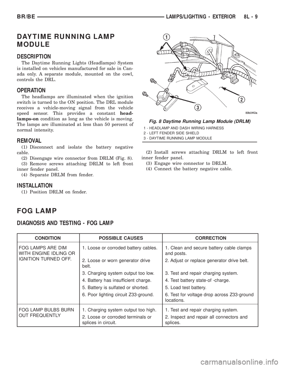
(2) Disengage wire connector from DRLM (Fig. 8).
(3) Remove screws attaching DRLM to left front
inner fender panel.
(4) Separate DRLM from fender.
INSTALLATION
(1) Position DRLM on fender.(2) Install screws attaching DRLM to left front
inner fender panel.
(3) Engage wire connector to DRLM.
(4) Connect the battery negative cable.
FOG LAMP
DIAGNOSIS AND TESTING - FOG LAMP
CONDITION POSSIBLE CAUSES CORRECTION
FOG LAMPS ARE DIM
WITH ENGINE IDLING OR
IGNITION TURNED OFF.1. Loose or corroded battery cables. 1. Clean and secure battery cable clamps
and posts.
2. Loose or worn generator drive
belt.2. Adjust or replace generator drive belt.
3. Charging system output too low. 3. Test and repair charging system.
4. Battery has insufficient charge. 4. Test battery state-of -charge.
5. Battery is sulfated or shorted. 5. Load test battery.
6. Poor lighting circuit Z33-ground. 6. Test for voltage drop across Z33-ground
locations.
FOG LAMP BULBS BURN
OUT FREQUENTLY1. Charging system output too high. 1. Test and repair charging system.
2. Loose or corroded terminals or
splices in circuit.2. Inspect and repair all connectors and
splices.
Fig. 8 Daytime Running Lamp Module (DRLM)
1 - HEADLAMP AND DASH WIRING HARNESS
2 - LEFT FENDER SIDE SHIELD
3 - DAYTIME RUNNING LAMP MODULE
BR/BELAMPS/LIGHTING - EXTERIOR 8L - 9
Page 607 of 2889
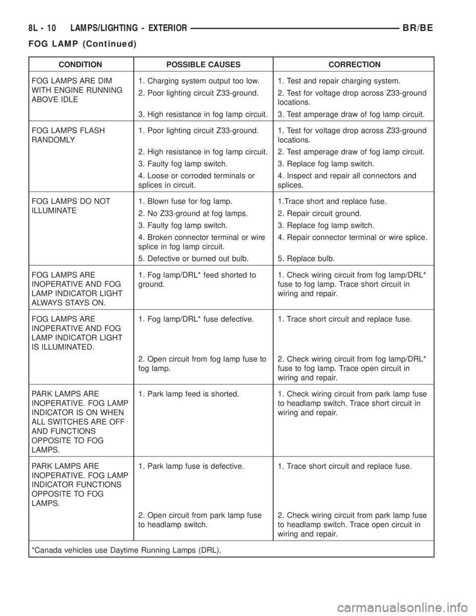
CONDITION POSSIBLE CAUSES CORRECTION
FOG LAMPS ARE DIM
WITH ENGINE RUNNING
ABOVE IDLE1. Charging system output too low. 1. Test and repair charging system.
2. Poor lighting circuit Z33-ground. 2. Test for voltage drop across Z33-ground
locations.
3. High resistance in fog lamp circuit. 3. Test amperage draw of fog lamp circuit.
FOG LAMPS FLASH
RANDOMLY1. Poor lighting circuit Z33-ground. 1. Test for voltage drop across Z33-ground
locations.
2. High resistance in fog lamp circuit. 2. Test amperage draw of fog lamp circuit.
3. Faulty fog lamp switch. 3. Replace fog lamp switch.
4. Loose or corroded terminals or
splices in circuit.4. Inspect and repair all connectors and
splices.
FOG LAMPS DO NOT
ILLUMINATE1. Blown fuse for fog lamp. 1.Trace short and replace fuse.
2. No Z33-ground at fog lamps. 2. Repair circuit ground.
3. Faulty fog lamp switch. 3. Replace fog lamp switch.
4. Broken connector terminal or wire
splice in fog lamp circuit.4. Repair connector terminal or wire splice.
5. Defective or burned out bulb. 5. Replace bulb.
FOG LAMPS ARE
INOPERATIVE AND FOG
LAMP INDICATOR LIGHT
ALWAYS STAYS ON.1. Fog lamp/DRL* feed shorted to
ground.1. Check wiring circuit from fog lamp/DRL*
fuse to fog lamp. Trace short circuit in
wiring and repair.
FOG LAMPS ARE
INOPERATIVE AND FOG
LAMP INDICATOR LIGHT
IS ILLUMINATED.1. Fog lamp/DRL* fuse defective. 1. Trace short circuit and replace fuse.
2. Open circuit from fog lamp fuse to
fog lamp.2. Check wiring circuit from fog lamp/DRL*
fuse to fog lamp. Trace open circuit in
wiring and repair.
PARK LAMPS ARE
INOPERATIVE. FOG LAMP
INDICATOR IS ON WHEN
ALL SWITCHES ARE OFF
AND FUNCTIONS
OPPOSITE TO FOG
LAMPS.1. Park lamp feed is shorted. 1. Check wiring circuit from park lamp fuse
to headlamp switch. Trace short circuit in
wiring and repair.
PARK LAMPS ARE
INOPERATIVE. FOG LAMP
INDICATOR FUNCTIONS
OPPOSITE TO FOG
LAMPS.1. Park lamp fuse is defective. 1. Trace short circuit and replace fuse.
2. Open circuit from park lamp fuse
to headlamp switch.2. Check wiring circuit from park lamp fuse
to headlamp switch. Trace open circuit in
wiring and repair.
*Canada vehicles use Daytime Running Lamps (DRL).
8L - 10 LAMPS/LIGHTING - EXTERIORBR/BE
FOG LAMP (Continued)
Page 608 of 2889
Additional fog lamp diagnostic procedures listed are for vehicles equipped with quad headlamps and the DRL
option.
CONDITION POSSIBLE CAUSES CORRECTION
FOG LAMPS ARE INOPERATIVE
AND FOG LAMP INDICATOR
S TAY S A LWAY S O N .1 Fog lamp/DRL* feed shorted to
ground.1. Check wiring circuit from fog
lamp/DRL* fuse to fog lamp.Trace
short circuit in wiring and repair.
FOG LAMP INDICATOR COMES
ON WITH OUT ILLUMINATING THE
FOG LAMPS1. Fog lamp/DRL* fuse defective. 1. Trace short circuit and replace
fuse.
FOG LAMPS INOPERATIVE WITH
INGNITION OFF.Open circuit from fog lamp fuse to
fog lamp.1. Check wiring circuit from fog
lamp/DRL* fuse to fog lamp. Trace
open circuit in wiring and repair.
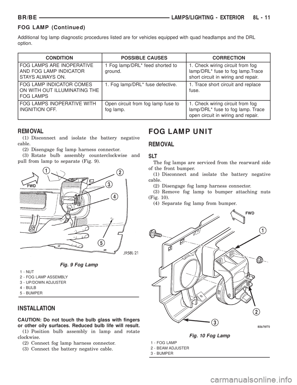
REMOVAL
(1) Disconnect and isolate the battery negative
cable.
(2) Disengage fog lamp harness connector.
(3) Rotate bulb assembly counterclockwise and
pull from lamp to separate (Fig. 9).
INSTALLATION
CAUTION: Do not touch the bulb glass with fingers
or other oily surfaces. Reduced bulb life will result.
(1) Position bulb assembly in lamp and rotate
clockwise.
(2) Connect fog lamp harness connector.
(3) Connect the battery negative cable.
FOG LAMP UNIT
REMOVAL
SLT
The fog lamps are serviced from the rearward side
of the front bumper.
(1) Disconnect and isolate the battery negative
cable.
(2) Disengage fog lamp harness connector.
(3) Remove fog lamp to bumper attaching nuts
(Fig. 10).
(4) Separate fog lamp from bumper.
Fig. 9 Fog Lamp
1 - NUT
2 - FOG LAMP ASSEMBLY
3 - UP/DOWN ADJUSTER
4 - BULB
5 - BUMPER
Fig. 10 Fog Lamp
1 - FOG LAMP
2 - BEAM ADJUSTER
3 - BUMPER
BR/BELAMPS/LIGHTING - EXTERIOR 8L - 11
FOG LAMP (Continued)
Page 609 of 2889
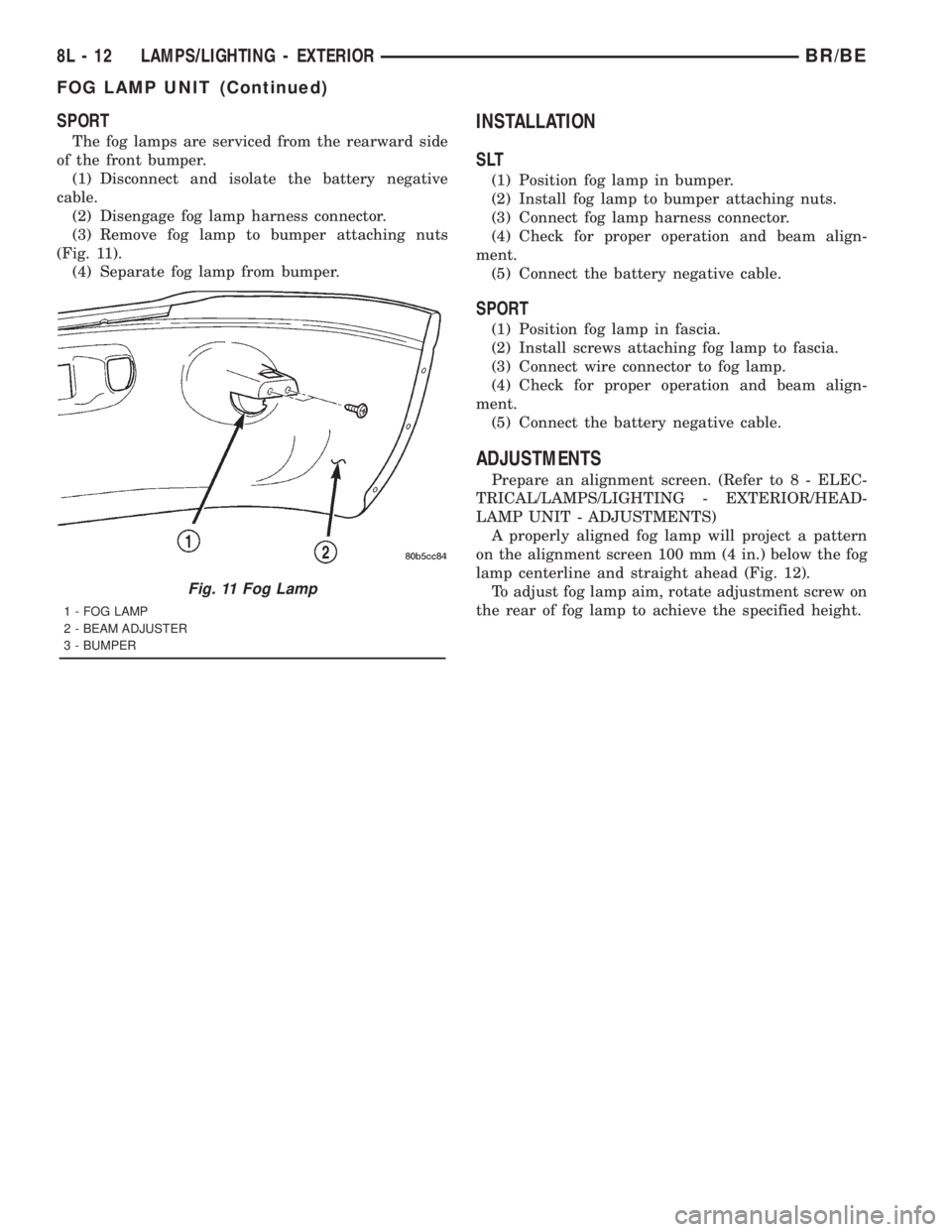
SPORT
The fog lamps are serviced from the rearward side
of the front bumper.
(1) Disconnect and isolate the battery negative
cable.
(2) Disengage fog lamp harness connector.
(3) Remove fog lamp to bumper attaching nuts
(Fig. 11).
(4) Separate fog lamp from bumper.
INSTALLATION
SLT
(1) Position fog lamp in bumper.
(2) Install fog lamp to bumper attaching nuts.
(3) Connect fog lamp harness connector.
(4) Check for proper operation and beam align-
ment.
(5) Connect the battery negative cable.
SPORT
(1) Position fog lamp in fascia.
(2) Install screws attaching fog lamp to fascia.
(3) Connect wire connector to fog lamp.
(4) Check for proper operation and beam align-
ment.
(5) Connect the battery negative cable.
ADJUSTMENTS
Prepare an alignment screen. (Refer to 8 - ELEC-
TRICAL/LAMPS/LIGHTING - EXTERIOR/HEAD-
LAMP UNIT - ADJUSTMENTS)
A properly aligned fog lamp will project a pattern
on the alignment screen 100 mm (4 in.) below the fog
lamp centerline and straight ahead (Fig. 12).
To adjust fog lamp aim, rotate adjustment screw on
the rear of fog lamp to achieve the specified height.
Fig. 11 Fog Lamp
1 - FOG LAMP
2 - BEAM ADJUSTER
3 - BUMPER
8L - 12 LAMPS/LIGHTING - EXTERIORBR/BE
FOG LAMP UNIT (Continued)