2001 DODGE RAM alarm
[x] Cancel search: alarmPage 453 of 2889

external connector receptacles that connect it to the
vehicle electrical system through one (base) or two
(high-line/premium) take outs with connectors from
the instrument panel wire harness.
The base version of the CTM is used on base mod-
els of this vehicle. It is also sometimes referred to as
the Integrated Electronic Module (IEM). The base
version of the CTM combines the functions of a
chime module and an intermittent wipe module in a
single unit. The high-line version of the CTM is used
on high-line vehicles. The high-line CTM provides all
of the functions of the base version of the CTM, but
also is used to control and integrate many additional
electronic functions and features included on high-
line models. The premium version of the CTM is the
same as the high-line version, but is used only on
models equipped with the heated seat option.
The high-line and premium versions of the CTM
utilize integrated circuitry and information carried
on the Chrysler Collision Detection (CCD) data bus
network along with many hard wired inputs to mon-
itor many sensor and switch inputs throughout the
vehicle. In response to those inputs, the internal cir-
cuitry and programming of the CTM allow it to con-
trol and integrate many electronic functions and
features of the vehicle through both hard wired out-
puts and the transmission of electronic message out-
puts to other electronic modules in the vehicle over
the CCD data bus.
The features that the CTM supports or controls
include the following:
²Automatic Door Lock- The high-line/premium
CTM provides an optional automatic door lock fea-
ture (also known as rolling door locks). This is a pro-
grammable feature.
²Central Locking- The high-line/premium CTM
provides an optional central locking/unlocking fea-
ture.
²Chimes- All versions of the CTM provide chime
service through an integral chime tone generator.
²Courtesy Lamps- The high-line/premium CTM
provides courtesy lamp control with timed load shed-
ding.
²Door Lock Inhibit- The high-line/premium
CTM provides a door lock inhibit feature.
²Enhanced Accident Response- The high-line/
premium CTM provides an optional enhanced acci-
dent response feature. This is a programmable
feature.
²Heated Seats- The premium CTM controls the
optional heated seat system by controlling the opera-
tion of the heated seat relay.
²Illuminated Entry- The high-line/premium
CTM provides a timed illuminated entry feature.²Intermittent Wipe Control- All versions of
the CTM provide control of the intermittent wipe
delay, and wipe-after-wash features.
²Panic Mode- The high-line/premium CTM pro-
vides support for the optional RKE system panic
mode features.
²Power Lock Control- The high-line/premium
CTM provides the optional power lock system fea-
tures, including support for the automatic door lock
and door lock inhibit modes.
²Programmable Features- The high-line/pre-
mium CTM provides support for certain programma-
ble features.
²Remote Keyless Entry- The high-line/pre-
mium CTM provides the optional Remote Keyless
Entry (RKE) system features, including support for
the RKE Lock (with optional horn chirp), Unlock,
Panic, and illuminated entry modes, as well as the
ability to be programmed to recognize up to four
RKE transmitters. The RKE horn chirp is a program-
mable feature.
²Remote Radio Switch Interface- The high-
line/premium CTM monitors and transmits the sta-
tus of the optional remote radio switches.
²Speed Sensitive Intermittent Wipe Control-
The high-line/premium CTM provides the speed sen-
sitive intermittent wipe feature.
²Vehicle Theft Alarm- The high-line/premium
CTM provides control of the optional Vehicle Theft
Alarm features, including support for the central
locking/unlocking mode.
Hard wired circuitry connects the CTM to the elec-
trical system of the vehicle. These hard wired circuits
are integral to several wire harnesses, which are
routed throughout the vehicle and retained by many
different methods. These circuits may be connected to
each other, to the vehicle electrical system and to the
CTM through the use of a combination of soldered
splices, splice block connectors, and many different
types of wire harness terminal connectors and insu-
lators. Refer to the appropriate wiring information.
The wiring information includes wiring diagrams,
proper wire and connector repair procedures, further
details on wire harness routing and retention, as well
as pin-out and location views for the various wire
harness connectors, splices and grounds.
All versions of the CTM for this model are serviced
only as a complete unit. Many of the electronic fea-
tures in the vehicle controlled or supported by the
high-line or premium versions of the CTM are pro-
grammable using the DRBIIItscan tool. In addition,
the high-line/premium CTM software is Flash com-
patible, which means it can be reprogrammed using
Flash reprogramming procedures. However, if any of
the CTM hardware components are damaged or
faulty, the entire CTM unit must be replaced. The
8E - 2 ELECTRONIC CONTROL MODULESBR/BE
BODY CONTROL/CENTRAL TIMER MODULE (Continued)
Page 721 of 2889

tem of the vehicle. These hard wired circuits are
integral to several wire harnesses, which are routed
throughout the vehicle and retained by many differ-
ent methods. These circuits may be connected to each
other, to the vehicle electrical system and to the
VTSS components through the use of a combination
of soldered splices, splice block connectors, and many
different types of wire harness terminal connectors
and insulators. Refer to the appropriate wiring infor-
mation. The wiring information includes wiring dia-
grams, proper wire and connector repair procedures,
further details on wire harness routing and reten-
tion, as well as pin-out and location views for the
various wire harness connectors, splices and grounds.
OPERATION
A Central Timer Module (CTM) is used on this
model to control and integrate many of the electronic
functions and features included in the Vehicle Theft
Security System (VTSS). In the VTSS, the CTM
receives inputs indicating the status of the door ajar
switches, the door cylinder lock switch, and the igni-
tion switch. The programming in the CTM allows it
to process the information from all of these inputs
and send control outputs to energize or de-energize
the horn relay, the headlamp relay, and the VTSS
indicator. The control of these inputs and outputs are
what constitute all of the features of the VTSS. Fol-
lowing is information on the operation of each of the
VTSS features. Refer to the owner's manual in the
vehicle glove box for more information on the fea-
tures, use and operation of the VTSS.
ENABLING
The high-line or premium version of the CTM must
have the VTSS function electronically enabled in
order for the VTSS to perform as designed. The logic
in the CTM keeps its VTSS function dormant until it
is enabled using a DRBIIIž scan tool. The VTSS
function of the high-line or premium CTM is enabled
on vehicles equipped with the VTSS option at the
factory, but a service replacement CTM must be
VTSS-enabled by the dealer using a DRBIIIž scan
tool. Refer to the appropriate diagnostic information.
The VTSS engine no-run feature is disabled when
it is shipped from the factory. This is done by pro-
gramming within the Powertrain Control Module
(PCM). The logic in the PCM prevents the VTSS
engine no-run feature from arming until the engine
start counter within the PCM sees twenty engine
starts. The VTSS no-run feature must be enabled by
the dealer when the vehicle is received from the
assembly plant. Once the VTSS engine no-run fea-
ture has been enabled, it cannot be disabled unless
the PCM is replaced with a new unit. The sameVTSS engine no-run feature enable logic will apply
anytime the PCM is replaced with a new unit.
ARMING
Passive arming of the VTSS occurs when the vehi-
cle is exited with the key removed from the ignition
switch, the headlamps are turned off, and the doors
are locked while they are open using the power lock
switch, or locked after they are closed by turning
either front door lock cylinder to the lock position
using the key. The power lock switch will not func-
tion if the key is in the ignition switch or the head-
lamps are turned on with the driver side front door
open. The VTSS will not arm if the doors are locked
using the mechanical lock button. Active arming of
the VTSS occurs when the ªLockº button on the
Remote Keyless Entry (RKE) transmitter is
depressed to lock the vehicle. For active arming to
occur, the doors must be closed and the ignition
switch must be in the Off position when the RKE
transmitter ªLockº button is depressed. However,
once the VTSS arming process has been completed,
the ignition switch can be turned to the Accessory
position without triggering the alarm.
Once the VTSS begins passive or active arming,
the security indicator lamp in the overhead console
will flash rapidly for about fifteen seconds. This indi-
cates that the VTSS arming is in progress. Turning a
key in the ignition switch, opening a door, or unlock-
ing a door by any means during the fifteen second
arming process will cause the VTSS indicator to stop
flashing and the arming process to abort. Once the
fifteen second arming function is successfully com-
pleted, the indicator will flash at a slower rate, indi-
cating that the VTSS is armed.
DISARMING
Passive disarming of the VTSS occurs when the
vehicle is unlocked using the key to unlock either
front door. Active disarming of the VTSS occurs when
the vehicle is unlocked by depressing the ªUnlockº
button of the RKE transmitter. Once the alarm has
been activated (horn pulsing, headlamps flashing,
and the engine no-run feature), either disarming
method will also deactivate the alarm. Depressing
the ªPanicº button on the RKE transmitter willnot
disarm the VTSS.
POWER-UP MODE
When the armed VTSS senses that the battery has
been disconnected and reconnected, it enters its pow-
er-up mode. In the power-up mode the alarm system
remains armed following a battery failure or discon-
nect. If the VTSS was armed prior to a battery dis-
connect or failure, the technician or vehicle operator
will have to actively or passively disarm the alarm
system after the battery is reconnected. The pow-
8Q - 2 VEHICLE THEFT SECURITYBR/BE
VEHICLE THEFT SECURITY (Continued)
Page 722 of 2889

er-up mode will also apply if the battery goes dead
while the system is armed, and battery jump-starting
is attempted. The engine no-run feature will prevent
the engine from starting until the alarm system has
been actively or passively disarmed. The VTSS will
be armed until the technician or vehicle operator has
actively or passively disarmed the alarm system. If
the VTSS is in the disarmed mode prior to a battery
disconnect or failure, it will remain disarmed after
the battery is reconnected or replaced, or if jump-
starting is attempted.
TAMPER ALERT
The VTSS tamper alert feature will sound the horn
three times upon disarming, if the alarm was trig-
gered and has since timed-out (about fifteen min-
utes). This feature alerts the vehicle operator that
the VTSS alarm was activated while the vehicle was
unattended.
DIAGNOSIS AND TESTING - VEHICLE THEFT
SECURITY SYSTEM
The VTSS-related hard wired inputs to and out-
puts from the high-line or premium Central Timer
Module (CTM) may be diagnosed and tested using
conventional diagnostic tools and procedures. Refer
to the appropriate wiring information. The wiring
information includes wiring diagrams, proper wire
and connector repair procedures, further details on
wire harness routing and retention, as well as pin-
out and location views for the various wire harness
connectors, splices and grounds.
However, conventional diagnostic methods may not
prove conclusive in the diagnosis of the CTM, the
Powertrain Control Module (PCM), or the Chrysler
Collision Detection (CCD) data bus network. In order
to obtain conclusive testing of the VTSS, the CTM,
the PCM, and the CCD data bus network must also
be checked. The most reliable, efficient, and accurate
means to diagnose the VTSS requires the use of a
DRBIIIž scan tool. Refer to the appropriate diagnos-
tic information. The DRBIIIž scan tool can provide
confirmation that the CCD data bus network is func-
tional, that all of the electronic modules are sending
and receiving the proper messages over the CCD
data bus, and that these modules are receiving the
proper hard wired inputs and responding with the
proper hard wired outputs needed to perform their
functions. See the ªVehicle Theft Security Systemº
menu item on the DRBIIIž scan tool.
WARNING: ON VEHICLES EQUIPPED WITH AIR-
BAGS, DISABLE THE AIRBAG SYSTEM BEFORE
ATTEMPTING ANY STEERING WHEEL, STEERING
COLUMN, OR INSTRUMENT PANEL COMPONENT
DIAGNOSIS OR SERVICE. DISCONNECT AND ISO-LATE THE BATTERY NEGATIVE (GROUND) CABLE,
THEN WAIT TWO MINUTES FOR THE AIRBAG SYS-
TEM CAPACITOR TO DISCHARGE BEFORE PER-
FORMING FURTHER DIAGNOSIS OR SERVICE. THIS
IS THE ONLY SURE WAY TO DISABLE THE AIRBAG
SYSTEM. FAILURE TO TAKE THE PROPER PRE-
CAUTIONS COULD RESULT IN ACCIDENTAL AIR-
BAG DEPLOYMENT AND POSSIBLE PERSONAL
INJURY.
VTSS INDICATOR
DESCRIPTION
The Vehicle Theft Security System (VTSS) indica-
tor consists of a red Light-Emitting Diode (LED)
located on the electronic circuit board of the Compass
Mini-Trip Computer (CMTC) within the overhead
console. The LED extends through a hole in the
CMTC lens located near the forward end of the over-
head console housing near the windshield.
The VTSS indicator cannot be adjusted or repaired
and, if faulty or damaged, the entire CMTC unit
must be replaced. (Refer to 8 - ELECTRICAL/OVER-
HEAD CONSOLE/COMPASS/MINI-TRIP COM-
PUTER - DESCRIPTION).
OPERATION
The Vehicle Theft Security System (VTSS) indica-
tor gives a visible indication of the VTSS arming sta-
tus. One side of Light-Emitting Diode (LED) in the
VTSS indicator is connected to battery current
through a fused B(+) circuit and a fuse in the Junc-
tion Block (JB), so the indicator remains functional
regardless of the ignition switch position. The other
side of the LED is hard wired to the Central Timer
Module (CTM), which controls the operation of the
VTSS indicator by pulling this side of the LED cir-
cuit to ground. When the VTSS arming is in
progress, the CTM will flash the LED rapidly on and
off for about fifteen seconds. When the VTSS has
been successfully armed, the CTM will flash the LED
on and off continually at a much slower rate until
the VTSS has been disarmed. The VTSS indicator
can be diagnosed using conventional diagnostic tools
and methods.
DIAGNOSIS AND TESTING - VTSS INDICATOR
The diagnosis found here addresses an inoperative
Vehicle Theft Security System (VTSS) indicator con-
dition. If the problem being diagnosed is related to
indicator accuracy, be certain to confirm that the
problem is with the indicator and not with an inop-
erative VTSS. (Refer to 8 - ELECTRICAL/VEHICLE
THEFT SECURITY SYSTEM- DIAGNOSIS AND
BR/BEVEHICLE THEFT SECURITY 8Q - 3
VEHICLE THEFT SECURITY (Continued)
Page 2836 of 2889

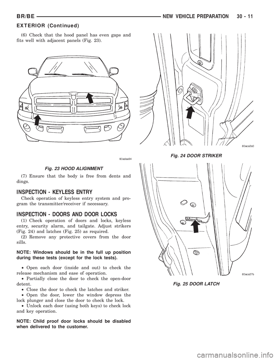
(6) Check that the hood panel has even gaps and
fits well with adjacent panels (Fig. 23).
(7) Ensure that the body is free from dents and
dings.
INSPECTION - KEYLESS ENTRY
Check operation of keyless entry system and pro-
gram the transmitter/receiver if necessary.
INSPECTION - DOORS AND DOOR LOCKS
(1) Check operation of doors and locks, keyless
entry, security alarm, and tailgate. Adjust strikers
(Fig. 24) and latches (Fig. 25) as required.
(2) Remove any protective covers from the door
sills.
NOTE: Windows should be in the full up position
during these tests (except for the lock tests).
²Open each door (inside and out) to check the
release mechanism and ease of operation.
²Partially close the door to check the open-door
detent.
²Close the door to check the latches and striker.
²Open the door, lower the window depress the
lock plunger and close the door to check the lock.
²Unlock each door (using both keys) to check lock
and key operation.
NOTE: Child proof door locks should be disabled
when delivered to the customer.
Fig. 23 HOOD ALIGNMENT
Fig. 24 DOOR STRIKER
Fig. 25 DOOR LATCH
BR/BENEW VEHICLE PREPARATION 30 - 11
EXTERIOR (Continued)