2001 DODGE RAM open hood
[x] Cancel search: open hoodPage 40 of 2889
JUMP STARTING
STANDARD PROCEDURE
WARNING: REVIEW ALL SAFETY PRECAUTIONS
AND WARNINGS IN GROUP 8A, BATTERY/START-
ING/CHARGING SYSTEMS DIAGNOSTICS. DO NOT
JUMP START A FROZEN BATTERY, PERSONAL
INJURY CAN RESULT. DO NOT JUMP START WHEN
MAINTENANCE FREE BATTERY INDICATOR DOT IS
YELLOW OR BRIGHT COLOR. DO NOT JUMP
START A VEHICLE WHEN THE BATTERY FLUID IS
BELOW THE TOP OF LEAD PLATES. DO NOT
ALLOW JUMPER CABLE CLAMPS TO TOUCH
EACH OTHER WHEN CONNECTED TO A BOOSTER
SOURCE. DO NOT USE OPEN FLAME NEAR BAT-
TERY. REMOVE METALLIC JEWELRY WORN ON
HANDS OR WRISTS TO AVOID INJURY BY ACCI-
DENTAL ARCING OF BATTERY CURRENT. WHEN
USING A HIGH OUTPUT BOOSTING DEVICE, DO
NOT ALLOW BATTERY VOLTAGE TO EXCEED 16
VOLTS. REFER TO INSTRUCTIONS PROVIDED
WITH DEVICE BEING USED.
CAUTION: When using another vehicle as a
booster, do not allow vehicles to touch. Electrical
systems can be damaged on either vehicle.
TO JUMP START A DISABLED VEHICLE:
(1) Raise hood on disabled vehicle and visually
inspect engine compartment for:
²Battery cable clamp condition, clean if necessary.
²Frozen battery.
²Yellow or bright color test indicator, if equipped.
²Low battery fluid level.
²Generator drive belt condition and tension.
²Fuel fumes or leakage, correct if necessary.
CAUTION: If the cause of starting problem on dis-
abled vehicle is severe, damage to booster vehicle
charging system can result.
(2) When using another vehicle as a booster
source, park the booster vehicle within cable reach.
Turn off all accessories, set the parking brake, place
the automatic transmission in PARK or the manual
transmission in NEUTRAL and turn the ignition
OFF.(3) On disabled vehicle, place gear selector in park
or neutral and set park brake. Turn off all accesso-
ries.
(4) Connect jumper cables to booster battery. RED
clamp to positive terminal (+). BLACK clamp to neg-
ative terminal (-). DO NOT allow clamps at opposite
end of cables to touch, electrical arc will result.
Review all warnings in this procedure.
(5) On disabled vehicle, connect RED jumper cable
clamp to positive (+) terminal. Connect BLACK
jumper cable clamp to engine ground as close to the
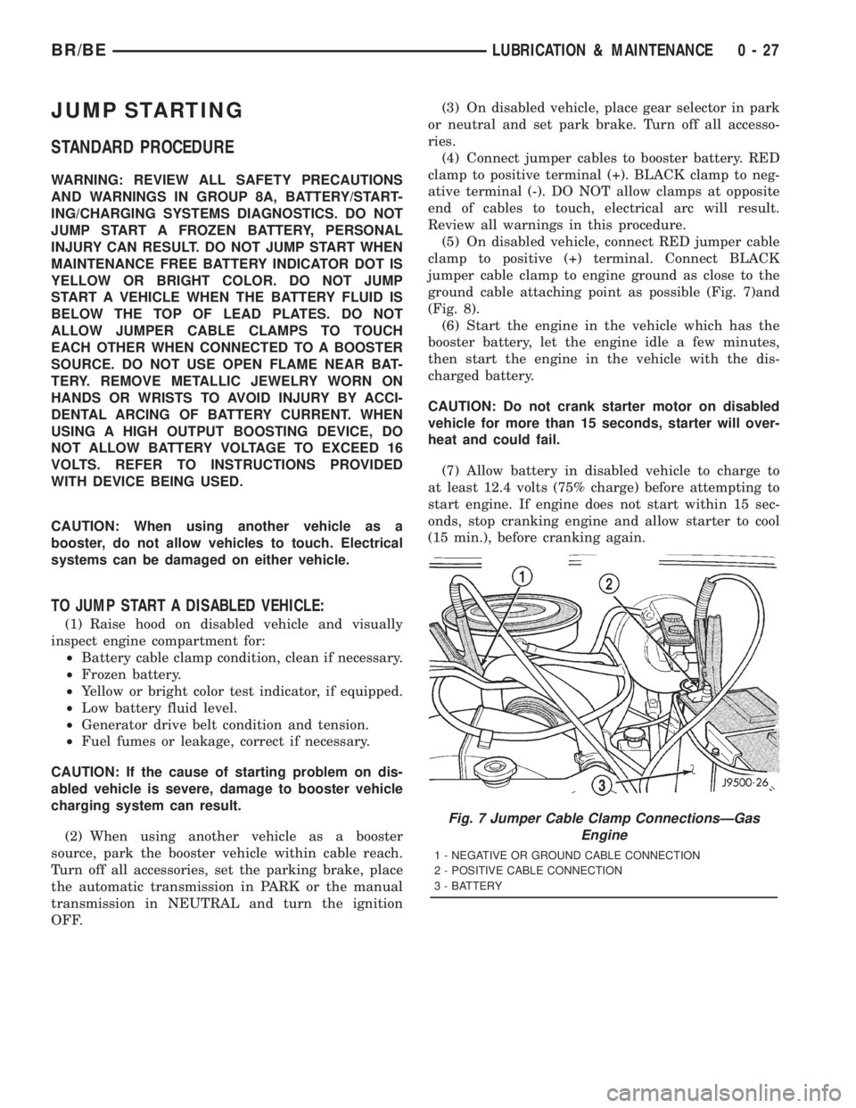
ground cable attaching point as possible (Fig. 7)and
(Fig. 8).
(6) Start the engine in the vehicle which has the
booster battery, let the engine idle a few minutes,
then start the engine in the vehicle with the dis-
charged battery.
CAUTION: Do not crank starter motor on disabled
vehicle for more than 15 seconds, starter will over-
heat and could fail.
(7) Allow battery in disabled vehicle to charge to
at least 12.4 volts (75% charge) before attempting to
start engine. If engine does not start within 15 sec-
onds, stop cranking engine and allow starter to cool
(15 min.), before cranking again.
Fig. 7 Jumper Cable Clamp ConnectionsÐGas
Engine
1 - NEGATIVE OR GROUND CABLE CONNECTION
2 - POSITIVE CABLE CONNECTION
3 - BATTERY
BR/BELUBRICATION & MAINTENANCE 0 - 27
Page 62 of 2889

(11) Install a new cotter pin in the hub nut.
Tighten the nut as needed to align the cotter pin hole
in the shaft with the opening in nut.
(12) Install the brake caliper, (Refer to 5 -
BRAKES/HYDRAULIC/MECHANICAL/DISC
BRAKE CALIPERS - INSTALLATION).
(13) Install the sensor wire to the steering knuckle
and frame and if equipped. Connect the wheel speed
sensor wire under the hood.
(14) Install the wheel and tire assemblies, (Refer
to 22 - TIRES/WHEELS/WHEELS - STANDARD
PROCEDURE).
(15) Remove the support and lower the vehicle.
(16) Apply the brakes several times to seat the
brake shoes and caliper piston. Do not move the vehi-
cle until a firm brake pedal is obtained.
INSTALLATION - 1500
(1) Apply a liberal quantity of anti-seize compound
to splines of the front drive shaft.
(2) Insert the bolts (Fig. 13) through back side of
the steering knuckle.
(3) Position the brake shield (Fig. 14) on bolts just
installed in the knuckle.
(4) Align the hub with the drive shaft and start
the shaft into the hub splines.
(5) Align the bolt holes in the hub bearing flange
with bolts installed in the knuckle. Then thread bolts
into the bearing flange.
(6) Tighten the hub bearing bolts to 166 N´m (122
ft. lbs.).
(7) Install the washer and axle hub nut and
tighten to 245 N´m (180 ft. lbs.).
Fig. 12 Brake Shield With Wheel Speed Sensor
1 - WHEEL SPEED SENSOR
2 - HUB BEARING
3 - SHIELD
Fig. 13 Hub Bearing Mounting Bolts
1 - KNUCKLE
2 - AXLE SPLINE
3 - HUB BEARING BOLTS
Fig. 14 Brake Shield
1 - KNUCKLE
2 - BRAKE SHIELD
3 - HUB BEARING BOLTS
BR/BEFRONT - 4WD 2 - 19
HUB / BEARING (Continued)
Page 561 of 2889
INSTRUMENT CLUSTER
DESCRIPTION
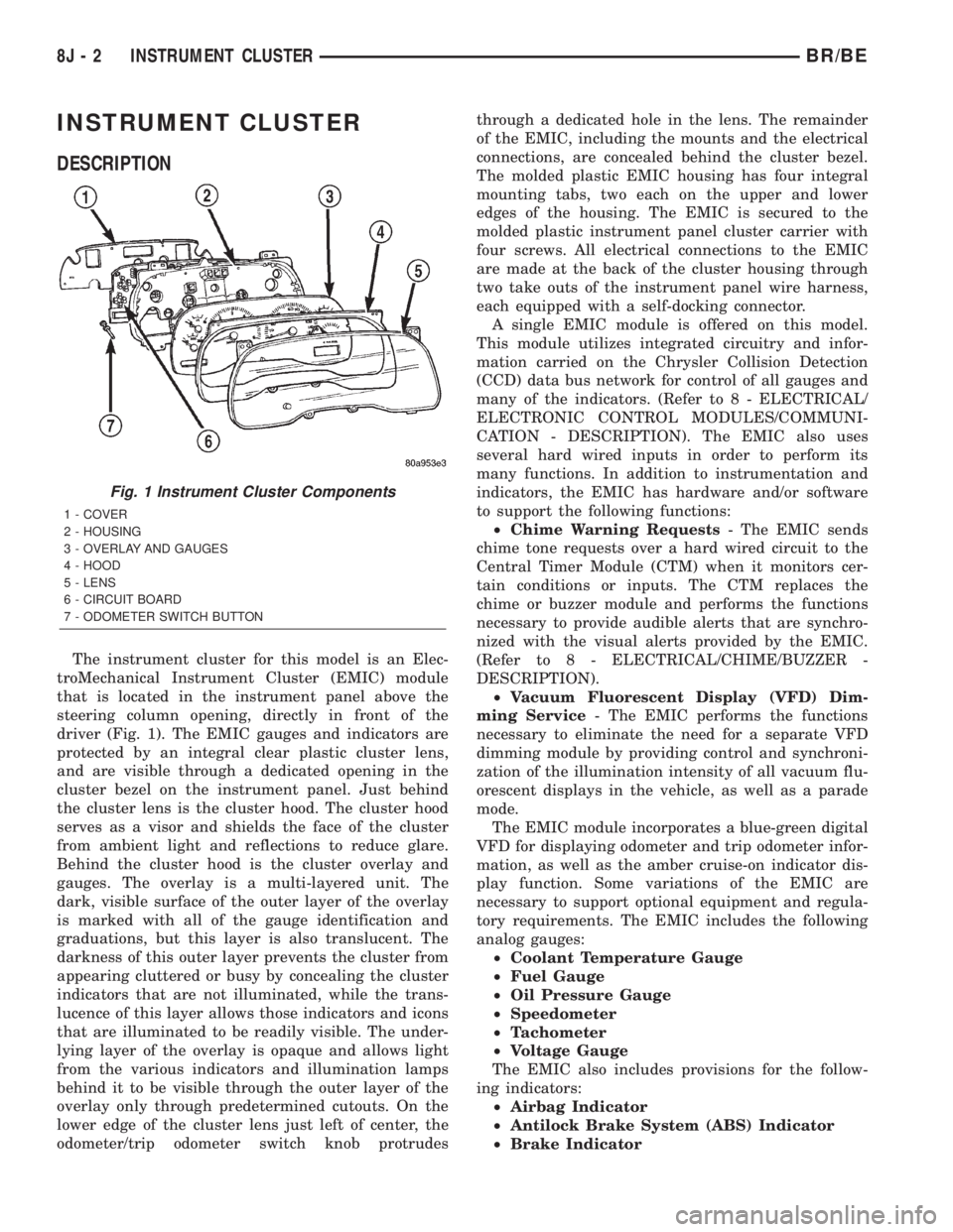
The instrument cluster for this model is an Elec-
troMechanical Instrument Cluster (EMIC) module
that is located in the instrument panel above the
steering column opening, directly in front of the
driver (Fig. 1). The EMIC gauges and indicators are
protected by an integral clear plastic cluster lens,
and are visible through a dedicated opening in the
cluster bezel on the instrument panel. Just behind
the cluster lens is the cluster hood. The cluster hood
serves as a visor and shields the face of the cluster
from ambient light and reflections to reduce glare.
Behind the cluster hood is the cluster overlay and
gauges. The overlay is a multi-layered unit. The
dark, visible surface of the outer layer of the overlay
is marked with all of the gauge identification and
graduations, but this layer is also translucent. The
darkness of this outer layer prevents the cluster from
appearing cluttered or busy by concealing the cluster
indicators that are not illuminated, while the trans-
lucence of this layer allows those indicators and icons
that are illuminated to be readily visible. The under-
lying layer of the overlay is opaque and allows light
from the various indicators and illumination lamps
behind it to be visible through the outer layer of the
overlay only through predetermined cutouts. On the
lower edge of the cluster lens just left of center, the
odometer/trip odometer switch knob protrudesthrough a dedicated hole in the lens. The remainder
of the EMIC, including the mounts and the electrical
connections, are concealed behind the cluster bezel.
The molded plastic EMIC housing has four integral
mounting tabs, two each on the upper and lower
edges of the housing. The EMIC is secured to the
molded plastic instrument panel cluster carrier with
four screws. All electrical connections to the EMIC
are made at the back of the cluster housing through
two take outs of the instrument panel wire harness,
each equipped with a self-docking connector.
A single EMIC module is offered on this model.
This module utilizes integrated circuitry and infor-
mation carried on the Chrysler Collision Detection
(CCD) data bus network for control of all gauges and
many of the indicators. (Refer to 8 - ELECTRICAL/
ELECTRONIC CONTROL MODULES/COMMUNI-
CATION - DESCRIPTION). The EMIC also uses
several hard wired inputs in order to perform its
many functions. In addition to instrumentation and
indicators, the EMIC has hardware and/or software
to support the following functions:
²Chime Warning Requests- The EMIC sends
chime tone requests over a hard wired circuit to the
Central Timer Module (CTM) when it monitors cer-
tain conditions or inputs. The CTM replaces the
chime or buzzer module and performs the functions
necessary to provide audible alerts that are synchro-
nized with the visual alerts provided by the EMIC.
(Refer to 8 - ELECTRICAL/CHIME/BUZZER -
DESCRIPTION).
²Vacuum Fluorescent Display (VFD) Dim-
ming Service- The EMIC performs the functions
necessary to eliminate the need for a separate VFD
dimming module by providing control and synchroni-
zation of the illumination intensity of all vacuum flu-
orescent displays in the vehicle, as well as a parade
mode.
The EMIC module incorporates a blue-green digital
VFD for displaying odometer and trip odometer infor-
mation, as well as the amber cruise-on indicator dis-
play function. Some variations of the EMIC are
necessary to support optional equipment and regula-
tory requirements. The EMIC includes the following
analog gauges:
²Coolant Temperature Gauge
²Fuel Gauge
²Oil Pressure Gauge
²Speedometer
²Tachometer
²Voltage Gauge
The EMIC also includes provisions for the follow-
ing indicators:
²Airbag Indicator
²Antilock Brake System (ABS) Indicator
²Brake Indicator
Fig. 1 Instrument Cluster Components
1 - COVER
2 - HOUSING
3 - OVERLAY AND GAUGES
4 - HOOD
5 - LENS
6 - CIRCUIT BOARD
7 - ODOMETER SWITCH BUTTON
8J - 2 INSTRUMENT CLUSTERBR/BE
Page 562 of 2889
²Check Gauges Indicator
²Cruise Indicator (Odometer VFD)
²Four-Wheel Drive Indicator
²High Beam Indicator
²Low Fuel Indicator
²Washer Fluid Indicator
²Malfunction Indicator Lamp (MIL)
²Overdrive-Off Indicator
²Seatbelt Indicator
²Service Reminder Indicator (SRI)
²Transmission Overtemp Indicator
²Turn Signal (Right and Left) Indicators
²Upshift Indicator
²Wait-To-Start Indicator (Diesel Only)
²Water-In-Fuel Indicator (Diesel Only)
Some of these indicators are either programmable
or automatically configured when the EMIC is con-
nected to the vehicle electrical system. This feature
allows those indicators to be activated or deactivated
for compatibility with certain optional equipment.
The EMIC also includes a provision for mounting the
automatic transmission gear selector indicator in the
lower right corner of the cluster. The spring-loaded,
cable driven, mechanical gear selector indicator gives
an indication of the transmission gear that has been
selected with the automatic transmission gear selec-
tor lever. The gear selector indicator pointer is easily
visible through an opening provided in the front of
the cluster overlay, and is also lighted by the cluster
illumination lamps for visibility at night. Models
equipped with a manual transmission have a block-
out plate installed in place of the gear selector indi-
cator.
Cluster illumination is accomplished by adjustable
incandescent back lighting, which illuminates the
gauges for visibility when the exterior lighting is
turned on. The EMIC high beam indicator, turn sig-
nal indicators, and wait-to-start indicator are also
illuminated by dedicated incandescent bulbs. The
remaining indicators in the EMIC are each illumi-
nated by a dedicated Light Emitting Diode (LED)
that is soldered onto the electronic circuit board.
Each of the incandescent bulbs is secured by an inte-
gral bulb holder to the electronic circuit board from
the back of the cluster housing.
Hard wired circuitry connects the EMIC to the
electrical system of the vehicle. These hard wired cir-
cuits are integral to several wire harnesses, which
are routed throughout the vehicle and retained by
many different methods. These circuits may be con-
nected to each other, to the vehicle electrical system
and to the EMIC through the use of a combination of
soldered splices, splice block connectors, and many
different types of wire harness terminal connectors
and insulators. Refer to the appropriate wiring infor-
mation. The wiring information includes wiring dia-grams, proper wire and connector repair procedures,
further details on wire harness routing and reten-
tion, as well as pin-out and location views for the
various wire harness connectors, splices and grounds.
The EMIC modules for this model are serviced only
as complete units. The EMIC module cannot be
adjusted or repaired. If a gauge, an LED indicator,
the VFD, the electronic circuit board, the circuit
board hardware, the cluster overlay, or the EMIC
housing are damaged or faulty, the entire EMIC mod-
ule must be replaced. The cluster lens and hood unit,
the rear cluster housing cover, the automatic trans-
mission gear selector indicator, and the incandescent
lamp bulbs with holders are available for individual
service replacement.
OPERATION
The ElectroMechanical Instrument Cluster (EMIC)
is designed to allow the vehicle operator to monitor
the conditions of many of the vehicle components and
operating systems. The gauges and indicators in the
EMIC provide valuable information about the various
standard and optional powertrains, fuel and emis-
sions systems, cooling systems, lighting systems,
safety systems and many other convenience items.
The EMIC is installed in the instrument panel so
that all of these monitors can be easily viewed by the
vehicle operator when driving, while still allowing
relative ease of access for service. The microproces-
sor-based EMIC hardware and software uses various
inputs to control the gauges and indicators visible on
the face of the cluster. Some of these inputs are hard
wired, but most are in the form of electronic mes-
sages that are transmitted by other electronic mod-
ules over the Chrysler Collision Detection (CCD) data
bus network. (Refer to 8 - ELECTRICAL/ELEC-
TRONIC CONTROL MODULES/COMMUNICATION
- OPERATION).
The EMIC microprocessor smooths the input data
using algorithms to provide gauge readings that are
accurate, stable and responsive to operating condi-
tions. These algorithms are designed to provide
gauge readings during normal operation that are con-
sistent with customer expectations. However, when
abnormal conditions exist, such as low/high battery
voltage, low oil pressure, or high coolant tempera-
ture, the algorithm drives the gauge pointer to an
extreme position and the microprocessor turns on the
Check Gauges indicator to provide a distinct visual
indication of a problem to the vehicle operator. The
instrument cluster circuitry may also generate a
hard wired chime tone request to the Central Timer
Module (CTM) when it monitors certain conditions or
inputs, in order to provide the vehicle operator with
an audible alert.
BR/BEINSTRUMENT CLUSTER 8J - 3
INSTRUMENT CLUSTER (Continued)
Page 570 of 2889
DISASSEMBLY
Some of the components for the instrument cluster
used in this vehicle are serviced individually. The
serviced components include: the automatic transmis-
sion gear selector indicator, the incandescent instru-
ment cluster indicator lamp and illumination lamp
bulbs (including the integral bulb holders), the clus-
ter lens and hood unit, and the cluster housing rear
cover. The remaining components are serviced only
as a part of the cluster housing unit, which includes:
the cluster housing, the electronic circuit board unit,
the cluster overlay, the gauges, and the odometer/trip
odometer reset switch button. Following are the pro-
cedures for disassembling the serviced components
from the instrument cluster unit.
WARNING: ON VEHICLES EQUIPPED WITH AIR-
BAGS, DISABLE THE AIRBAG SYSTEM BEFORE
ATTEMPTING ANY STEERING WHEEL, STEERING
COLUMN, OR INSTRUMENT PANEL COMPONENT
DIAGNOSIS OR SERVICE. DISCONNECT AND ISO-
LATE THE BATTERY NEGATIVE (GROUND) CABLE,
THEN WAIT TWO MINUTES FOR THE AIRBAG SYS-
TEM CAPACITOR TO DISCHARGE BEFORE PER-
FORMING FURTHER DIAGNOSIS OR SERVICE. THIS
IS THE ONLY SURE WAY TO DISABLE THE AIRBAG
SYSTEM. FAILURE TO TAKE THE PROPER PRE-
CAUTIONS COULD RESULT IN ACCIDENTAL AIR-
BAG DEPLOYMENT AND POSSIBLE PERSONAL
INJURY.GEAR SELECTOR INDICATOR
(1) Disconnect and isolate the battery negative
cable.
(2) Remove the instrument cluster from the instru-
ment panel. (Refer to 8 - ELECTRICAL/INSTRU-
MENT CLUSTER - REMOVAL).
(3) Remove the steering column opening cover
from the instrument panel. (Refer to 23 - BODY/IN-
STRUMENT PANEL/STEERING COLUMN OPEN-
ING COVER - REMOVAL).
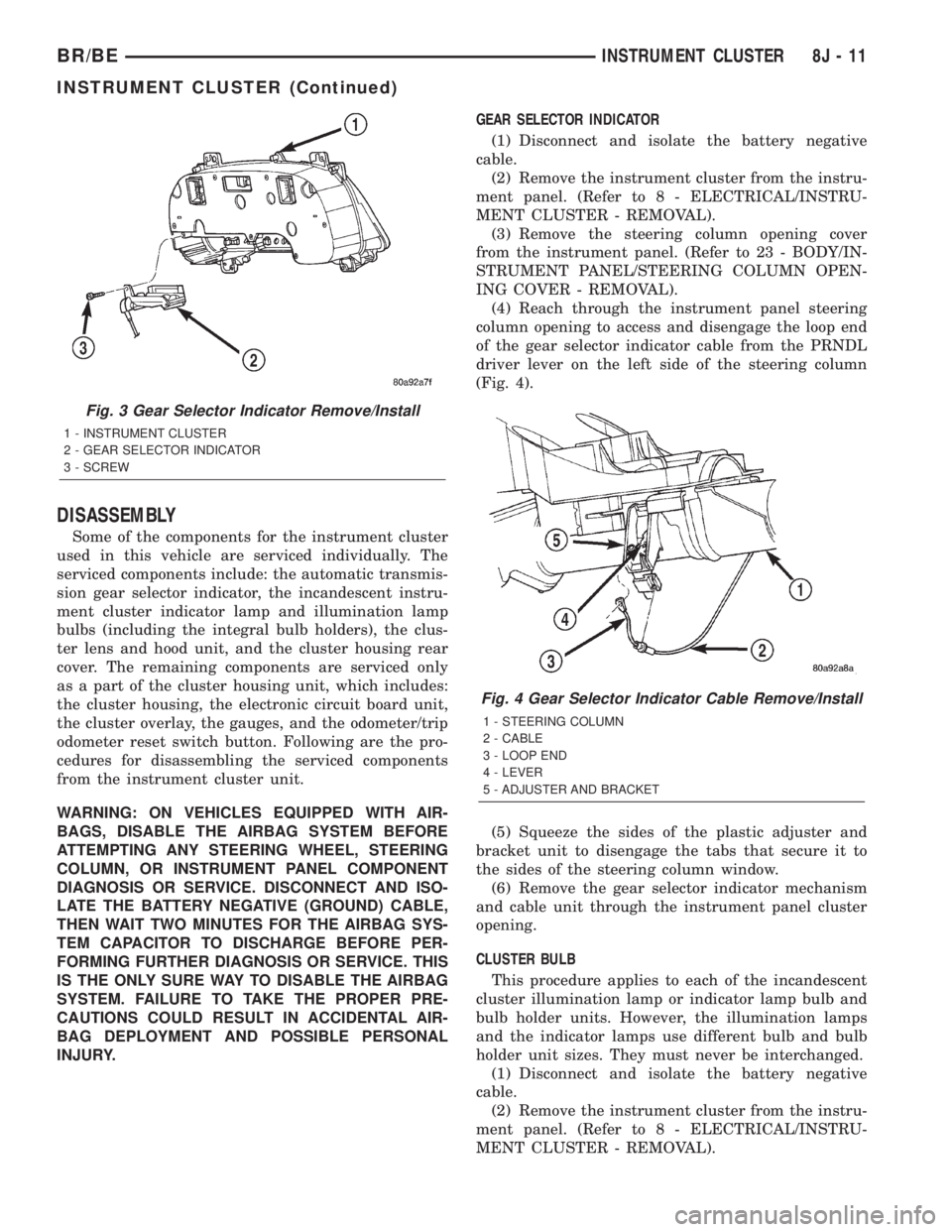
(4) Reach through the instrument panel steering
column opening to access and disengage the loop end
of the gear selector indicator cable from the PRNDL
driver lever on the left side of the steering column
(Fig. 4).
(5) Squeeze the sides of the plastic adjuster and
bracket unit to disengage the tabs that secure it to
the sides of the steering column window.
(6) Remove the gear selector indicator mechanism
and cable unit through the instrument panel cluster
opening.
CLUSTER BULB
This procedure applies to each of the incandescent
cluster illumination lamp or indicator lamp bulb and
bulb holder units. However, the illumination lamps
and the indicator lamps use different bulb and bulb
holder unit sizes. They must never be interchanged.
(1) Disconnect and isolate the battery negative
cable.
(2) Remove the instrument cluster from the instru-
ment panel. (Refer to 8 - ELECTRICAL/INSTRU-
MENT CLUSTER - REMOVAL).
Fig. 3 Gear Selector Indicator Remove/Install
1 - INSTRUMENT CLUSTER
2 - GEAR SELECTOR INDICATOR
3 - SCREW
Fig. 4 Gear Selector Indicator Cable Remove/Install
1 - STEERING COLUMN
2 - CABLE
3 - LOOP END
4 - LEVER
5 - ADJUSTER AND BRACKET
BR/BEINSTRUMENT CLUSTER 8J - 11
INSTRUMENT CLUSTER (Continued)
Page 572 of 2889
ASSEMBLY
WARNING: ON VEHICLES EQUIPPED WITH AIR-
BAGS, DISABLE THE AIRBAG SYSTEM BEFORE
ATTEMPTING ANY STEERING WHEEL, STEERING
COLUMN, OR INSTRUMENT PANEL COMPONENT
DIAGNOSIS OR SERVICE. DISCONNECT AND ISO-
LATE THE BATTERY NEGATIVE (GROUND) CABLE,
THEN WAIT TWO MINUTES FOR THE AIRBAG SYS-
TEM CAPACITOR TO DISCHARGE BEFORE PER-
FORMING FURTHER DIAGNOSIS OR SERVICE. THIS
IS THE ONLY SURE WAY TO DISABLE THE AIRBAG
SYSTEM. FAILURE TO TAKE THE PROPER PRE-
CAUTIONS COULD RESULT IN ACCIDENTAL AIR-
BAG DEPLOYMENT AND POSSIBLE PERSONAL
INJURY.
GEAR SELECTOR INDICATOR
(1) Position the gear selector indicator mechanism
and cable unit into the instrument panel cluster
opening.
(2) Route the cable through the instrument panel
and under the steering column to the PRNDL driver
lever on the left side of the steering column.
(3) Squeeze the sides of the plastic adjuster and
bracket unit and engage the tabs that secure it with
the sides of the steering column window.
(4) Engage the loop end of the gear selector indi-
cator cable onto the PRNDL driver lever on the left
side of the steering column (Fig. 4).
(5) Reinstall the instrument cluster onto the
instrument panel. (Refer to 8 - ELECTRICAL/IN-
STRUMENT CLUSTER - INSTALLATION).
(6) Confirm proper operation of the gear selector
indicator. Calibrate the indicator, if required. (Refer
to 19 - STEERING/COLUMN - INSTALLATION).
(7) Reinstall the steering column opening cover
onto the instrument panel. (Refer to 23 - BODY/IN-
STRUMENT PANEL/STEERING COLUMN OPEN-
ING COVER - INSTALLATION).
(8) Reconnect the battery negative cable.
CLUSTER BULB
This procedure applies to each of the incandescent
cluster illumination lamp or indicator lamp bulb and
bulb holder units. However, the illumination lamps
and the indicator lamps use different bulb and bulb
holder unit sizes. They must never be interchanged.
CAUTION: Be certain that any bulb and bulb holder
unit removed from the cluster electronic circuit
board is reinstalled in the correct position. Always
use the correct bulb size and type for replacement.
An incorrect bulb size or type may overheat and
cause damage to the instrument cluster, the elec-
tronic circuit board and/or the gauges.(1) Insert the bulb and bulb holder unit straight
into the correct bulb mounting hole in the cluster
electronic circuit board (Fig. 5).
(2) With the bulb holder fully seated against the
cluster electronic circuit board, turn the bulb holder
clockwise about sixty degrees to lock it into place.
(3) Reinstall the instrument cluster onto the
instrument panel. (Refer to 8 - ELECTRICAL/IN-
STRUMENT CLUSTER - INSTALLATION).
(4) Reconnect the battery negative cable.
CLUSTER LENS AND HOOD
CAUTION: Do not touch the face of the gauge over-
lay or the back of the cluster lens with your finger.
It will leave a permanent finger print.
(1) Align the cluster lens and hood unit with the
cluster housing. Be certain that the odometer/trip
odometer switch button is installed through the
clearance hole in the lens (Fig. 6).
(2) Install and tighten the seven screws that
secure the lens and hood unit to the cluster housing.
Tighten the screws to 2.2 N´m (20 in. lbs.).
(3) Reinstall the instrument cluster onto the
instrument panel. (Refer to 8 - ELECTRICAL/IN-
STRUMENT CLUSTER - INSTALLATION).
(4) Reconnect the battery negative cable.
CLUSTER HOUSING REAR COVER
(1) Position the rear cover onto the back of the
cluster housing (Fig. 7).
(2) Install and tighten the six screws that secure
the rear cover to the back of the cluster housing.
Tighten the screws to 2.2 N´m (20 in. lbs.).
(3) Reinstall the instrument cluster onto the
instrument panel. (Refer to 8 - ELECTRICAL/IN-
STRUMENT CLUSTER - INSTALLATION).
(4) Reconnect the battery negative cable.
CLUSTER HOUSING
(1) Assemble the rear cover onto the cluster hous-
ing. Refer to CLUSTER HOUSING REAR COVER .
(2) Assemble the lens and hood unit onto the clus-
ter housing. Refer to CLUSTER LENS AND HOOD .
(3) Reinstall the instrument cluster onto the
instrument panel. (Refer to 8 - ELECTRICAL/IN-
STRUMENT CLUSTER - INSTALLATION).
(4) Reconnect the battery negative cable.
BR/BEINSTRUMENT CLUSTER 8J - 13
INSTRUMENT CLUSTER (Continued)
Page 599 of 2889
MARKER LAMP
REMOVAL..............................22
INSTALLATION...........................23
MULTI-FUNCTION SWITCH
DESCRIPTION...........................23
OPERATION.............................24
DIAGNOSIS AND TESTING.................25
MULTI-FUNCTION SWITCH...............25
REMOVAL..............................27
INSTALLATION...........................28
OUTBOARD IDENTIFICATION LAMP
REMOVAL..............................28
INSTALLATION...........................29
PARK/TURN SIGNAL LAMP
REMOVAL..............................29
INSTALLATION...........................29
PARK/TURN SIGNAL LAMP UNIT
REMOVAL..............................29INSTALLATION...........................29
TAIL LAMP
DESCRIPTION...........................29
OPERATION.............................29
REMOVAL..............................29
INSTALLATION...........................30
TAIL LAMP UNIT
REMOVAL..............................30
INSTALLATION...........................30
TURN SIGNAL CANCEL CAM
DESCRIPTION...........................30
OPERATION.............................31
UNDERHOOD LAMP
REMOVAL..............................31
INSTALLATION...........................32
UNDERHOOD LAMP UNIT
REMOVAL..............................32
INSTALLATION...........................32
LAMPS/LIGHTING - EXTERIOR
DESCRIPTION - TURN SIGNAL & HAZARD
WARNING SYSTEM
A turn signal and hazard warning system is stan-
dard factory-installed safety equipment on this
model. The turn signal and hazard warning system
includes the following major components, which are
described in further detail elsewhere in this service
information:
²Combination Flasher- The electronic combi-
nation flasher is installed in the Junction Block (JB),
which is located behind the fuse access panel on the
left outboard end of the instrument panel.
²Hazard Warning Switch- The hazard warning
switch is integral to the multi-function switch on the
left side of the steering column. The hazard warning
switch button protrudes from a dedicated opening in
the shroud on the top of the steering column, just
below the steering wheel.
²Turn Signal Cancel Cam- The turn signal
cancel cam is integral to the clockspring, which is
located beneath the steering column shrouds at the
top of the steering column, just below the steering
wheel.
²Turn Signal Indicators- The two turn signal
indicators, one right and one left, are integral to the
ElectroMechanical Instrument Cluster (EMIC)
located in the instrument panel.
²Turn Signal Lamps- The front turn signal
lamps are integral to the lower front outboard ends
of the headlamp modules, located just outboard of the
two sides of the radiator grille opening. The rear
turn signal lamps are integral to the taillamp mod-
ules located on either side of the vehicle. For pickup
models the taillamp modules are secured to the rear
of the quarter panels at each side of the tailgate
opening. For cab and chassis models the taillampmodules are secured by a stamped steel bracket on
the outboard side of each frame rail near the rear of
the vehicle.
²Turn Signal Switch- The turn signal switch is
integral to the multi-function switch on the left side
of the steering column. The multi-function switch
control stalk that actuates the turn signal switch
protrudes from a dedicated opening in the steering
column shrouds on the left side of the column, just
below the steering wheel.
Hard wired circuitry connects the turn signal and
hazard warning system components to each other
through the electrical system of the vehicle. These
hard wired circuits are integral to several wire har-
nesses, which are routed throughout the vehicle and
retained by many different methods. These circuits
may be connected to each other, to the vehicle elec-
trical system and to the turn signal and hazard
warning system components through the use of a
combination of soldered splices, splice block connec-
tors and many different types of wire harness termi-
nal connectors and insulators. Refer to the
appropriate wiring information. The wiring informa-
tion includes wiring diagrams, proper wire and con-
nector repair procedures, details of wire harness
routing and retention, connector pin-out information
and location views for the various wire harness con-
nectors, splices and grounds.
OPERATION - TURN SIGNAL & HAZARD
WARNING SYSTEM
The turn signal system operates on battery current
received on a fused ignition switch output (run-acc)
circuit so that the turn signals will only operate with
the ignition switch in the On or Accessory positions.
The hazard warning system operates on non-
switched battery current received on a fused B(+) cir-
cuit so that the hazard warning remains operational
8L - 2 LAMPS/LIGHTING - EXTERIORBR/BE
Page 601 of 2889
(9) Disconnect the instrument panel wire harness
connector for the multi-function switch from the
switch connector receptacle. Check for continuity
between the hazard flasher signal circuit cavities in
the JB receptacle for the combination flasher and the
instrument panel wire harness connector for the
multi-function switch. There should be continuity. If
OK, go to Step 10. If not OK, repair the open hazard
flasher signal circuit between the JB and the multi-
function switch as required.
(10) Check for continuity between the flasher out-
put circuit cavities of the JB receptacle for the com-
bination flasher and in the instrument panel wire
harness connector for the multi-function switch.
There should be continuity. If OK, test the multi-
function switch. (Refer to 8 - ELECTRICAL/LAMPS/
LIGHTING - EXTERIOR/MULTI-FUNCTION
SWITCH - DIAGNOSIS AND TESTING). If not OK,
repair the open flasher output circuit between the JB
and the multi-function switch as required.
SPECIFICATIONS
EXTERIOR LAMPS
LAMP BULB
Back-up 3157
Cargo 921
Center High Mounted
Stop921
Clearance Roof Mounted 168
Fog Lamps 896
Headlamp - SLT 9004LL
Headlamp - Sport Low
Beam9007
Headlamp - Sport High
Beam9004LL
License Plate w/o
Bumper1155
License Plate -Step
Bumper168
Park/Turn Signal 3157NA
Snow Plow Control 161
Tail/Brake/Turn Signal 3157
Tail/Brake/Cab - Chassis 1157
Underhood 105
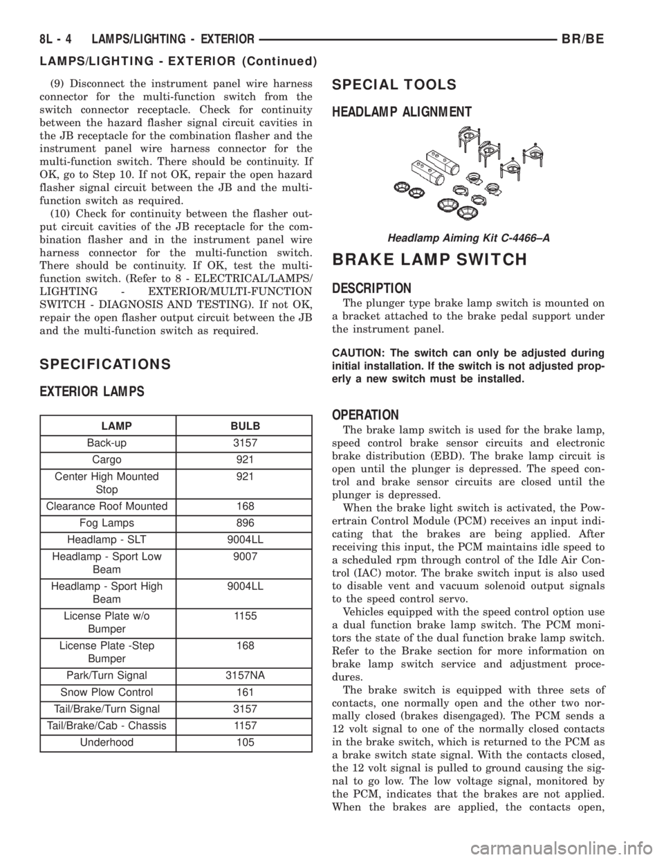
SPECIAL TOOLS
HEADLAMP ALIGNMENT
BRAKE LAMP SWITCH
DESCRIPTION
The plunger type brake lamp switch is mounted on
a bracket attached to the brake pedal support under
the instrument panel.
CAUTION: The switch can only be adjusted during
initial installation. If the switch is not adjusted prop-
erly a new switch must be installed.
OPERATION
The brake lamp switch is used for the brake lamp,
speed control brake sensor circuits and electronic
brake distribution (EBD). The brake lamp circuit is
open until the plunger is depressed. The speed con-
trol and brake sensor circuits are closed until the
plunger is depressed.
When the brake light switch is activated, the Pow-
ertrain Control Module (PCM) receives an input indi-
cating that the brakes are being applied. After
receiving this input, the PCM maintains idle speed to
a scheduled rpm through control of the Idle Air Con-
trol (IAC) motor. The brake switch input is also used
to disable vent and vacuum solenoid output signals
to the speed control servo.
Vehicles equipped with the speed control option use
a dual function brake lamp switch. The PCM moni-
tors the state of the dual function brake lamp switch.
Refer to the Brake section for more information on
brake lamp switch service and adjustment proce-
dures.
The brake switch is equipped with three sets of
contacts, one normally open and the other two nor-
mally closed (brakes disengaged). The PCM sends a
12 volt signal to one of the normally closed contacts
in the brake switch, which is returned to the PCM as
a brake switch state signal. With the contacts closed,
the 12 volt signal is pulled to ground causing the sig-
nal to go low. The low voltage signal, monitored by
the PCM, indicates that the brakes are not applied.
When the brakes are applied, the contacts open,
Headlamp Aiming Kit C-4466±A
8L - 4 LAMPS/LIGHTING - EXTERIORBR/BE
LAMPS/LIGHTING - EXTERIOR (Continued)