2001 DODGE RAM mirror controls
[x] Cancel search: mirror controlsPage 518 of 2889
MIRROR SWITCH
DESCRIPTION
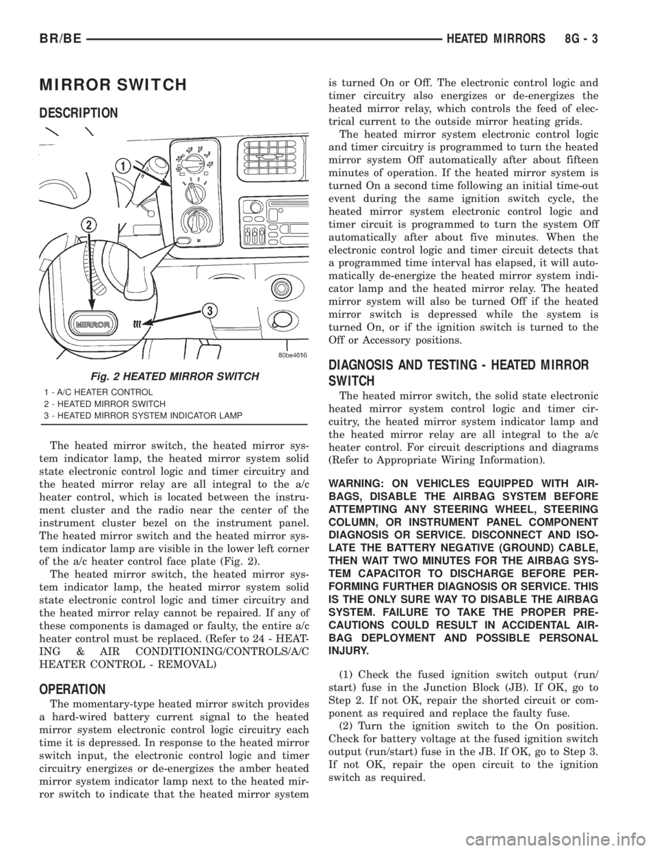
The heated mirror switch, the heated mirror sys-
tem indicator lamp, the heated mirror system solid
state electronic control logic and timer circuitry and
the heated mirror relay are all integral to the a/c
heater control, which is located between the instru-
ment cluster and the radio near the center of the
instrument cluster bezel on the instrument panel.
The heated mirror switch and the heated mirror sys-
tem indicator lamp are visible in the lower left corner
of the a/c heater control face plate (Fig. 2).
The heated mirror switch, the heated mirror sys-
tem indicator lamp, the heated mirror system solid
state electronic control logic and timer circuitry and
the heated mirror relay cannot be repaired. If any of
these components is damaged or faulty, the entire a/c
heater control must be replaced. (Refer to 24 - HEAT-
ING & AIR CONDITIONING/CONTROLS/A/C
HEATER CONTROL - REMOVAL)
OPERATION
The momentary-type heated mirror switch provides
a hard-wired battery current signal to the heated
mirror system electronic control logic circuitry each
time it is depressed. In response to the heated mirror
switch input, the electronic control logic and timer
circuitry energizes or de-energizes the amber heated
mirror system indicator lamp next to the heated mir-
ror switch to indicate that the heated mirror systemis turned On or Off. The electronic control logic and
timer circuitry also energizes or de-energizes the
heated mirror relay, which controls the feed of elec-
trical current to the outside mirror heating grids.
The heated mirror system electronic control logic
and timer circuitry is programmed to turn the heated
mirror system Off automatically after about fifteen
minutes of operation. If the heated mirror system is
turned On a second time following an initial time-out
event during the same ignition switch cycle, the
heated mirror system electronic control logic and
timer circuit is programmed to turn the system Off
automatically after about five minutes. When the
electronic control logic and timer circuit detects that
a programmed time interval has elapsed, it will auto-
matically de-energize the heated mirror system indi-
cator lamp and the heated mirror relay. The heated
mirror system will also be turned Off if the heated
mirror switch is depressed while the system is
turned On, or if the ignition switch is turned to the
Off or Accessory positions.
DIAGNOSIS AND TESTING - HEATED MIRROR
SWITCH
The heated mirror switch, the solid state electronic
heated mirror system control logic and timer cir-
cuitry, the heated mirror system indicator lamp and
the heated mirror relay are all integral to the a/c
heater control. For circuit descriptions and diagrams
(Refer to Appropriate Wiring Information).
WARNING: ON VEHICLES EQUIPPED WITH AIR-
BAGS, DISABLE THE AIRBAG SYSTEM BEFORE
ATTEMPTING ANY STEERING WHEEL, STEERING
COLUMN, OR INSTRUMENT PANEL COMPONENT
DIAGNOSIS OR SERVICE. DISCONNECT AND ISO-
LATE THE BATTERY NEGATIVE (GROUND) CABLE,
THEN WAIT TWO MINUTES FOR THE AIRBAG SYS-
TEM CAPACITOR TO DISCHARGE BEFORE PER-
FORMING FURTHER DIAGNOSIS OR SERVICE. THIS
IS THE ONLY SURE WAY TO DISABLE THE AIRBAG
SYSTEM. FAILURE TO TAKE THE PROPER PRE-
CAUTIONS COULD RESULT IN ACCIDENTAL AIR-
BAG DEPLOYMENT AND POSSIBLE PERSONAL
INJURY.
(1) Check the fused ignition switch output (run/
start) fuse in the Junction Block (JB). If OK, go to
Step 2. If not OK, repair the shorted circuit or com-
ponent as required and replace the faulty fuse.
(2) Turn the ignition switch to the On position.
Check for battery voltage at the fused ignition switch
output (run/start) fuse in the JB. If OK, go to Step 3.
If not OK, repair the open circuit to the ignition
switch as required.
Fig. 2 HEATED MIRROR SWITCH
1 - A/C HEATER CONTROL
2 - HEATED MIRROR SWITCH
3 - HEATED MIRROR SYSTEM INDICATOR LAMP
BR/BEHEATED MIRRORS 8G - 3
Page 662 of 2889
(3) Remove the nut that secures the power mirror
switch to the driver side front door trim panel.
(4) Remove the trim panel from the inside of the
driver side front door. (Refer to 23 - BODY/DOOR -
FRONT/TRIM PANEL - REMOVAL) for the proce-
dures.
(5) Pull the trim panel away from the inner door
far enough to access the power mirror switch wire
harness connector.
(6) Unplug the power mirror switch wire harness
connector.
(7) Remove the power mirror switch from the back
of the door trim panel.
INSTALLATION
(1) Insert the power mirror switch to the back of
the door trim panel.
(2) Connect the power mirror switch to the har-
ness connector.
(3) Install the trim panel to the inside of the
driver side door. (Refer to 23 - BODY/DOOR -
FRONT/TRIM PANEL - INSTALLATION).
(4) Install the nut that secures the power mirror
switch to the driver side front door.
(5) Push the control knob on to the power mirror
switch.
(6) Connect the battery negative cable.
SIDEVIEW MIRROR
DESCRIPTION
Each power mirror head contains two electric
motors, two drive mechanisms, and the mirror glass.
One motor and drive controls mirror up-and-down
movement, and the other controls right-and-left
movement.
OPERATION
The power mirrors in vehicles equipped with the
available heated mirror system option also include an
electric heating grid located behind the mirror glass.
This heating grid is energized by the heated mirror
relay in the heater and air conditioner control only
when the ignition switch is in the On position, and
the heated mirror system is turned on. (Refer to 8 -
ELECTRICAL/HEATED MIRRORS - DESCRIP-
TION) for more information.
The power mirror assembly cannot be repaired. If
any component of the power mirror unit is faulty or
damaged, the entire assembly must be replaced.
DIAGNOSIS AND TESTING - SIDEVIEW
MIRROR
For circuit descriptions and diagrams, refer to the
appropriate wiring information. The wiring informa-
tion includes wiring diagrams, proper wire and con-
nector repair procedures, details of wire harness
routing and retention, connector pin-out information
and location views for the various wire harness con-
nectors, splices and grounds.
(1) Check the fuses in the Power Distribution Cen-
ter (PDC) and the junction block. If OK, go to Step 2.
If not OK, repair the shorted circuit or component as
required and replace the faulty fuse(s).
(2) Check for battery voltage at the fuse in the
junction block. If OK, go to Step 3. If not OK, repair
the open circuit to the PDC as required.
(3) Disconnect and isolate the battery negative
cable. Remove the driver side door trim panel and
unplug the wire harness connector from the power
mirror switch. Connect the battery negative cable.
Check for battery voltage at the fused B(+) circuit
cavity in the door wire harness half of the power mir-
ror switch wire harness connector. If OK, go to Step
4. If not OK, repair the open circuit to the junction
block as required.
BR/BEPOWER MIRRORS 8N - 13
POWER MIRROR SWITCH (Continued)
Page 2747 of 2889
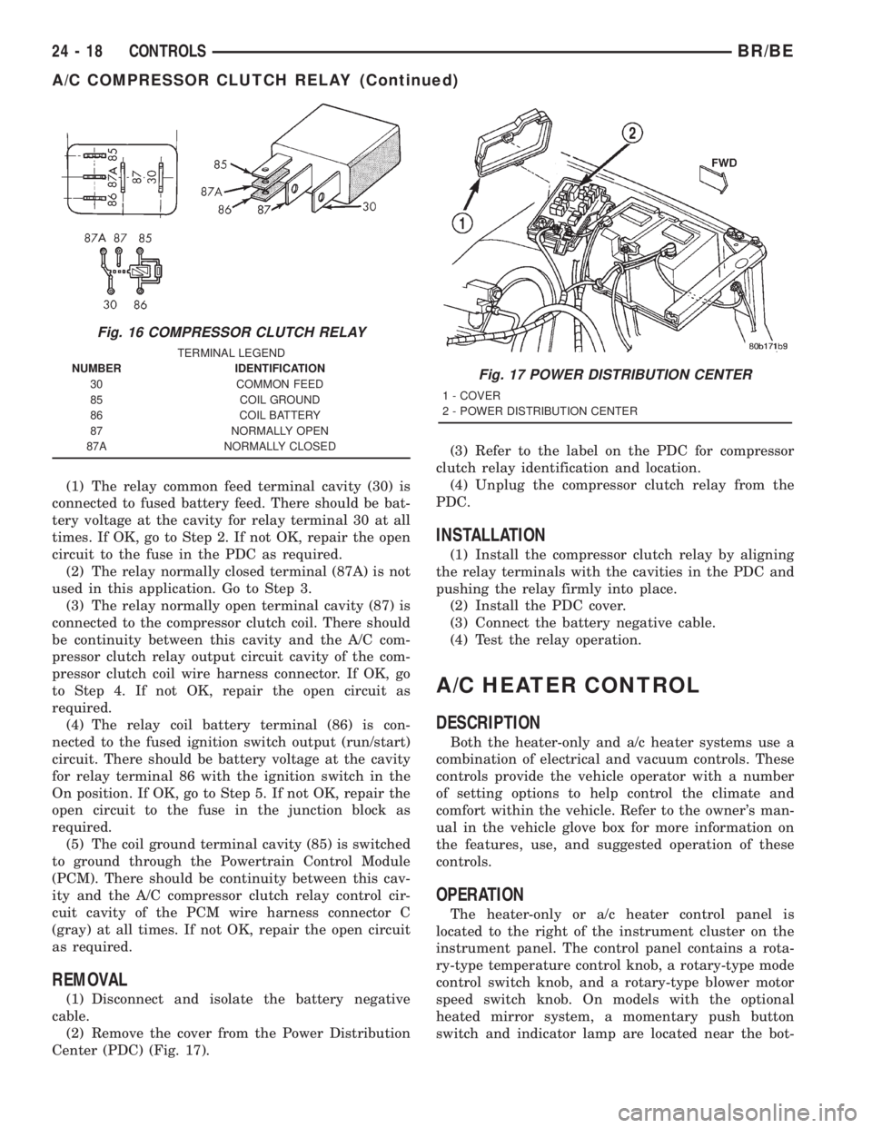
(1) The relay common feed terminal cavity (30) is
connected to fused battery feed. There should be bat-
tery voltage at the cavity for relay terminal 30 at all
times. If OK, go to Step 2. If not OK, repair the open
circuit to the fuse in the PDC as required.
(2) The relay normally closed terminal (87A) is not
used in this application. Go to Step 3.
(3) The relay normally open terminal cavity (87) is
connected to the compressor clutch coil. There should
be continuity between this cavity and the A/C com-
pressor clutch relay output circuit cavity of the com-
pressor clutch coil wire harness connector. If OK, go
to Step 4. If not OK, repair the open circuit as
required.
(4) The relay coil battery terminal (86) is con-
nected to the fused ignition switch output (run/start)
circuit. There should be battery voltage at the cavity
for relay terminal 86 with the ignition switch in the
On position. If OK, go to Step 5. If not OK, repair the
open circuit to the fuse in the junction block as
required.
(5) The coil ground terminal cavity (85) is switched
to ground through the Powertrain Control Module
(PCM). There should be continuity between this cav-
ity and the A/C compressor clutch relay control cir-
cuit cavity of the PCM wire harness connector C
(gray) at all times. If not OK, repair the open circuit
as required.
REMOVAL
(1) Disconnect and isolate the battery negative
cable.
(2) Remove the cover from the Power Distribution
Center (PDC) (Fig. 17).(3) Refer to the label on the PDC for compressor
clutch relay identification and location.
(4) Unplug the compressor clutch relay from the
PDC.
INSTALLATION
(1) Install the compressor clutch relay by aligning
the relay terminals with the cavities in the PDC and
pushing the relay firmly into place.
(2) Install the PDC cover.
(3) Connect the battery negative cable.
(4) Test the relay operation.
A/C HEATER CONTROL
DESCRIPTION
Both the heater-only and a/c heater systems use a
combination of electrical and vacuum controls. These
controls provide the vehicle operator with a number
of setting options to help control the climate and
comfort within the vehicle. Refer to the owner's man-
ual in the vehicle glove box for more information on
the features, use, and suggested operation of these
controls.
OPERATION
The heater-only or a/c heater control panel is
located to the right of the instrument cluster on the
instrument panel. The control panel contains a rota-
ry-type temperature control knob, a rotary-type mode
control switch knob, and a rotary-type blower motor
speed switch knob. On models with the optional
heated mirror system, a momentary push button
switch and indicator lamp are located near the bot-
Fig. 16 COMPRESSOR CLUTCH RELAY
TERMINAL LEGEND
NUMBER IDENTIFICATION
30 COMMON FEED
85 COIL GROUND
86 COIL BATTERY
87 NORMALLY OPEN
87A NORMALLY CLOSED
Fig. 17 POWER DISTRIBUTION CENTER
1 - COVER
2 - POWER DISTRIBUTION CENTER
24 - 18 CONTROLSBR/BE
A/C COMPRESSOR CLUTCH RELAY (Continued)
Page 2748 of 2889
tom of the a/c heater control panel. Refer to Heated
Mirrors for more information on this feature.
The heater-only or a/c heater control panel cannot
be repaired. If faulty or damaged, the entire unit
must be replaced. The control knobs and the illumi-
nation lamps are available for service replacement.
DIAGNOSIS AND TESTING - A/C HEATER
CONTROL
Satisfactory heater and air conditioner perfor-
mance depends upon proper operation and adjust-
ment of all operating controls and refrigeration
system components. For circuit descriptions and dia-
grams, (Refer to Appropriate Wiring Information).
These inspections, tests, and adjustments should be
used to locate the cause of a malfunction.
Operation must be tested as described in the fol-
lowing sequence:
(1) Inspect and adjust the serpentine drive belt.
Refer to Cooling for the procedures.
(2) Start the engine and hold the idle speed at
1,300 rpm.
(3) On vehicles with air conditioning, turn the
temperature control knob to the extreme counter-
clockwise (Cool) position, and set the mode control
switch knob to the Bi-Level (A/C) position. The out-
side (recirculation) air door should be open to outside
air. If not OK, (Refer to 24 - HEATING & AIR CON-
DITIONING/CONTROLS - DIAGNOSIS AND TEST-
ING - VACUUM SYSTEM).
(4) Open the vehicle windows. Test the blower
motor operation in all speeds. If not OK, (Refer to 24
- HEATING & AIR CONDITIONING/DISTRIBU-
TION/BLOWER MOTOR - DIAGNOSIS AND TEST-
ING).
(5) On vehicles with air conditioning, the compres-
sor should be running and the air conditioning sys-
tem in operation unless the ambient air temperature
is below about -1É C (30É F). If not OK, (Refer to 24 -
HEATING & AIR CONDITIONING - DIAGNOSIS
AND TESTING - A/C PERFORMANCE).
(6) Check the mode control switch operation. The
heater and air conditioner systems should respond as
described in the owner's manual in the vehicle glove
box to each mode selected. Reduce the engine speed
to normal idle. The vacuum will be high at low idle
and the vacuum actuators should respond quickly. If
not OK, (Refer to 24 - HEATING & AIR CONDI-
TIONING/CONTROLS - DIAGNOSIS AND TEST-
ING - VACUUM SYSTEM).
(7) If the vacuum tests, and the electrical compo-
nent and circuit tests reveal no problems, disassem-
ble the HVAC housing to inspect for mechanical
misalignment or binding of the mode doors. (Refer to
24 - HEATING & AIR CONDITIONING/DISTRIBU-
TION/HVAC HOUSING - DISASSEMBLY)
REMOVAL
WARNING: ON VEHICLES EQUIPPED WITH AIR-
BAGS, DISABLE THE AIRBAG SYSTEM BEFORE
ATTEMPTING ANY STEERING WHEEL, STEERING
COLUMN, OR INSTRUMENT PANEL COMPONENT
DIAGNOSIS OR SERVICE. DISCONNECT AND ISO-
LATE THE BATTERY NEGATIVE (GROUND) CABLE,
THEN WAIT TWO MINUTES FOR THE AIRBAG SYS-
TEM CAPACITOR TO DISCHARGE BEFORE PER-
FORMING FURTHER DIAGNOSIS OR SERVICE. THIS
IS THE ONLY SURE WAY TO DISABLE THE AIRBAG
SYSTEM. FAILURE TO TAKE THE PROPER PRE-
CAUTIONS COULD RESULT IN AN ACCIDENTAL
AIRBAG DEPLOYMENT AND POSSIBLE PERSONAL
INJURY.
(1) Disconnect and isolate the battery negative
cable.
(2) Reach under the instrument panel near the
driver side of the floor panel transmission tunnel and
unplug the a/c heater control to HVAC housing vac-
uum harness connector.
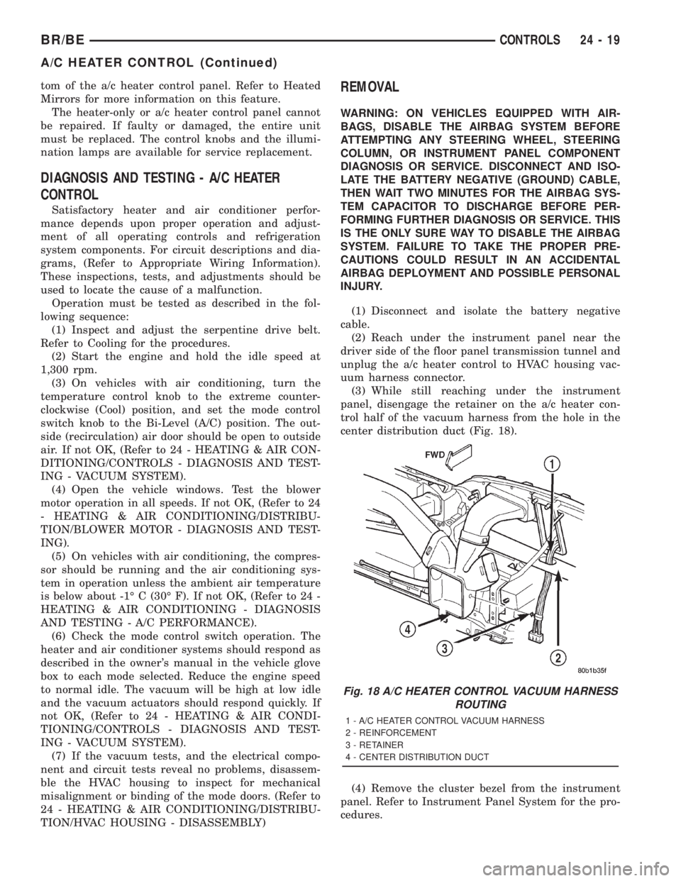
(3) While still reaching under the instrument
panel, disengage the retainer on the a/c heater con-
trol half of the vacuum harness from the hole in the
center distribution duct (Fig. 18).
(4) Remove the cluster bezel from the instrument
panel. Refer to Instrument Panel System for the pro-
cedures.
Fig. 18 A/C HEATER CONTROL VACUUM HARNESS
ROUTING
1 - A/C HEATER CONTROL VACUUM HARNESS
2 - REINFORCEMENT
3 - RETAINER
4 - CENTER DISTRIBUTION DUCT
BR/BECONTROLS 24 - 19
A/C HEATER CONTROL (Continued)
Page 2749 of 2889
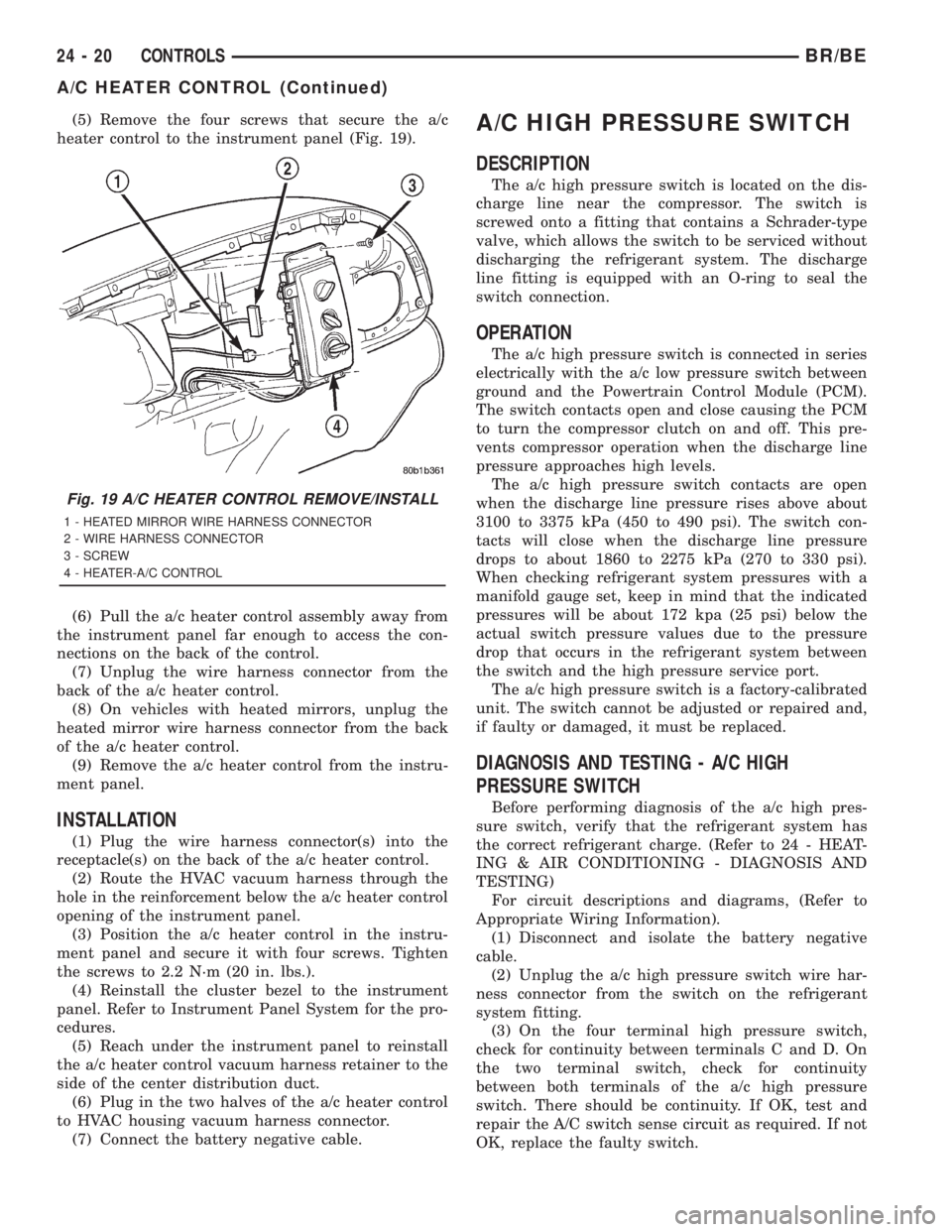
(5) Remove the four screws that secure the a/c
heater control to the instrument panel (Fig. 19).
(6) Pull the a/c heater control assembly away from
the instrument panel far enough to access the con-
nections on the back of the control.
(7) Unplug the wire harness connector from the
back of the a/c heater control.
(8) On vehicles with heated mirrors, unplug the
heated mirror wire harness connector from the back
of the a/c heater control.
(9) Remove the a/c heater control from the instru-
ment panel.
INSTALLATION
(1) Plug the wire harness connector(s) into the
receptacle(s) on the back of the a/c heater control.
(2) Route the HVAC vacuum harness through the
hole in the reinforcement below the a/c heater control
opening of the instrument panel.
(3) Position the a/c heater control in the instru-
ment panel and secure it with four screws. Tighten
the screws to 2.2 N´m (20 in. lbs.).
(4) Reinstall the cluster bezel to the instrument
panel. Refer to Instrument Panel System for the pro-
cedures.
(5) Reach under the instrument panel to reinstall
the a/c heater control vacuum harness retainer to the
side of the center distribution duct.
(6) Plug in the two halves of the a/c heater control
to HVAC housing vacuum harness connector.
(7) Connect the battery negative cable.
A/C HIGH PRESSURE SWITCH
DESCRIPTION
The a/c high pressure switch is located on the dis-
charge line near the compressor. The switch is
screwed onto a fitting that contains a Schrader-type
valve, which allows the switch to be serviced without
discharging the refrigerant system. The discharge
line fitting is equipped with an O-ring to seal the
switch connection.
OPERATION
The a/c high pressure switch is connected in series
electrically with the a/c low pressure switch between
ground and the Powertrain Control Module (PCM).
The switch contacts open and close causing the PCM
to turn the compressor clutch on and off. This pre-
vents compressor operation when the discharge line
pressure approaches high levels.
The a/c high pressure switch contacts are open
when the discharge line pressure rises above about
3100 to 3375 kPa (450 to 490 psi). The switch con-
tacts will close when the discharge line pressure
drops to about 1860 to 2275 kPa (270 to 330 psi).
When checking refrigerant system pressures with a
manifold gauge set, keep in mind that the indicated
pressures will be about 172 kpa (25 psi) below the
actual switch pressure values due to the pressure
drop that occurs in the refrigerant system between
the switch and the high pressure service port.
The a/c high pressure switch is a factory-calibrated
unit. The switch cannot be adjusted or repaired and,
if faulty or damaged, it must be replaced.
DIAGNOSIS AND TESTING - A/C HIGH
PRESSURE SWITCH
Before performing diagnosis of the a/c high pres-
sure switch, verify that the refrigerant system has
the correct refrigerant charge. (Refer to 24 - HEAT-
ING & AIR CONDITIONING - DIAGNOSIS AND
TESTING)
For circuit descriptions and diagrams, (Refer to
Appropriate Wiring Information).
(1) Disconnect and isolate the battery negative
cable.
(2) Unplug the a/c high pressure switch wire har-
ness connector from the switch on the refrigerant
system fitting.
(3) On the four terminal high pressure switch,
check for continuity between terminals C and D. On
the two terminal switch, check for continuity
between both terminals of the a/c high pressure
switch. There should be continuity. If OK, test and
repair the A/C switch sense circuit as required. If not
OK, replace the faulty switch.
Fig. 19 A/C HEATER CONTROL REMOVE/INSTALL
1 - HEATED MIRROR WIRE HARNESS CONNECTOR
2 - WIRE HARNESS CONNECTOR
3 - SCREW
4 - HEATER-A/C CONTROL
24 - 20 CONTROLSBR/BE
A/C HEATER CONTROL (Continued)