2001 DODGE RAM fuel cap
[x] Cancel search: fuel capPage 14 of 2889
LUBRICATION & MAINTENANCE
TABLE OF CONTENTS
page page
LUBRICATION & MAINTENANCE
DESCRIPTION............................1
INTERNATIONAL SYMBOLS
DESCRIPTION............................3
PARTS & LUBRICANT RECOMMENDATION
STANDARD PROCEDURE...................3
FLUID TYPES
DESCRIPTION............................3
OPERATION.............................5
FLUID CAPACITIES
SPECIFICATIONS.........................6MAINTENANCE SCHEDULES
DESCRIPTION............................7
JUMP STARTING
STANDARD PROCEDURE..................27
HOISTING
STANDARD PROCEDURE..................28
TOWING
STANDARD PROCEDURE..................29
LUBRICATION &
MAINTENANCE
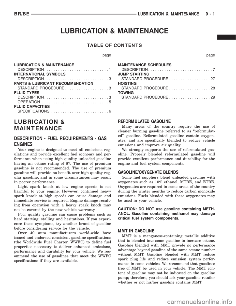
DESCRIPTION - FUEL REQUIREMENTS - GAS
ENGINES
Your engine is designed to meet all emissions reg-
ulations and provide excellent fuel economy and per-
formance when using high quality unleaded gasoline
having an octane rating of 87. The use of premium
gasoline is not recommended. The use of premium
gasoline will provide no benefit over high quality reg-
ular gasoline, and in some circumstances may result
in poorer performance.
Light spark knock at low engine speeds is not
harmful to your engine. However, continued heavy
spark knock at high speeds can cause damage and
immediate service is required. Engine damage result-
ing from operation with a heavy spark knock may
not be covered by the new vehicle warranty.
Poor quality gasoline can cause problems such as
hard starting, stalling and hesitations. If you experi-
ence these symptoms, try another brand of gasoline
before considering service for the vehicle.
Over 40 auto manufacturers world-wide have
issued and endorsed consistent gasoline specifications
(the Worldwide Fuel Charter, WWFC) to define fuel
properties necessary to deliver enhanced emissions,
performance and durability for your vehicle. We rec-
ommend the use of gasolines that meet the WWFC
specifications if they are available.
REFORMULATED GASOLINE
Many areas of the country require the use of
cleaner burning gasoline referred to as ªreformulat-
edº gasoline. Reformulated gasoline contain oxygen-
ates, and are specifically blended to reduce vehicle
emissions and improve air quality.
We strongly supports the use of reformulated gas-
oline. Properly blended reformulated gasoline will
provide excellent performance and durability for the
engine and fuel system components.
GASOLINE/OXYGENATE BLENDS
Some fuel suppliers blend unleaded gasoline with
oxygenates such as 10% ethanol, MTBE, and ETBE.
Oxygenates are required in some areas of the country
during the winter months to reduce carbon monoxide
emissions. Fuels blended with these oxygenates may
be used in your vehicle.
CAUTION: DO NOT use gasoline containing METH-
ANOL. Gasoline containing methanol may damage
critical fuel system components.
MMT IN GASOLINE
MMT is a manganese-containing metallic additive
that is blended into some gasoline to increase octane.
Gasoline blended with MMT provide no performance
advantage beyond gasoline of the same octane number
without MMT. Gasoline blended with MMT reduce
spark plug life and reduce emission system perfor-
mance in some vehicles. We recommend that gasolines
free of MMT be used in your vehicle. The MMT con-
tent of gasoline may not be indicated on the gasoline
pump; therefore, you should ask your gasoline retailer
whether or not his/her gasoline contains MMT.
BR/BELUBRICATION & MAINTENANCE 0 - 1
Page 19 of 2889
FLUID CAPACITIES
SPECIFICATIONS
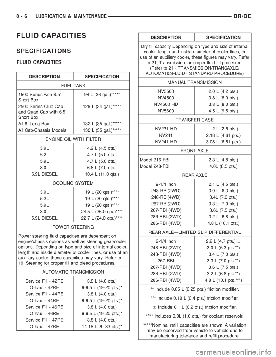
FLUID CAPACITIES
DESCRIPTION SPECIFICATION
FUEL TANK
1500 Series with 6.5'
Short Box98 L (26 gal.)*****
2500 Series Club Cab
and Quad Cab with 6.5'
Short Box129 L (34 gal.)*****
All 8' Long Box 132 L (35 gal.)*****
All Cab/Chassis Models 132 L (35 gal.)*****
ENGINE OIL WITH FILTER
3.9L 4.2 L (4.5 qts.)
5.2L 4.7 L (5.0 qts.)
5.9L 4.7 L (5.0 qts.)
8.0L 6.6 L (7.0 qts.)
5.9L DIESEL 10.4 L (11.0 qts.)
COOLING SYSTEM
3.9L 19 L (20 qts.)****
5.2L 19 L (20 qts.)****
5.9L 19 L (20 qts.)****
8.0L 24.5 L (26.0 qts.)****
5.9L DIESEL 22.7 L (24.0 qts.)****
POWER STEERING
Power steering fluid capacities are dependent on
engine/chassis options as well as steering gear/cooler
options. Depending on type and size of internal cooler,
length and inside diameter of cooler lines, or use of an
auxiliary cooler, these capacities may vary. Refer to
19, Steering for proper fill and bleed procedures.
AUTOMATIC TRANSMISSION
Service Fill - 42RE 3.8 L (4.0 qts.)
O-haul - 42RE 9-9.5 L (19-20 pts.)*
Service Fill - 44RE 3.8 L (4.0 qts.)
O-haul - 44RE 9-9.5 L (19-20 pts.)*
Service Fill - 46RE 3.8 L (4.0 qts.)
O-haul - 46RE 9-9.5 L (19-20 pts.)*
Service Fill - 47RE 3.8 L (4.0 qts.)
O-haul - 47RE 14-16 L 29-33 pts.)*
DESCRIPTION SPECIFICATION
Dry fill capacity Depending on type and size of internal
cooler, length and inside diameter of cooler lines, or
use of an auxiliary cooler, these figures may vary. Refer
to 21, Transmission for proper fluid fill procedure.
(Refer to 21 - TRANSMISSION/TRANSAXLE/
AUTOMATIC/FLUID - STANDARD PROCEDURE)
MANUAL TRANSMISSION
NV3500 2.0 L (4.2 pts.)
NV4500 3.8 L (8.0 pts.)
NV4500 HD 3.8 L (8.0 pts.)
NV5600 4.5 L (9.5 pts.)
TRANSFER CASE
NV231 HD 1.2 L (2.5 pts.)
NV241 2.18 L (4.61 pts.)
NV241 HD 3.08 L (6.51 pts.)
FRONT AXLE
Model 216-FBI 2.3 L (4.8 pts.)
Model 248-FBI 4.0L (8.5 pts.)
REAR AXLE
9-1/4 inch 2.1 L (4.5 pts.)
248-RBI(2WD) 3.0 L (6.3 pts.)
248-RBI(4WD) 3.4L (7.0 pts.)
267-RBI(2WD) 3.3 L (7.0 pts.)
267-RBI (4WD) 3.6L (7.5 pts.)
286-RBI (2WD) 3.2 L (6.8 pts.)
286-RBI (4WD) 4.8 L (10.1 pts.)
REAR AXLEÐLIMITED SLIP DIFFERENTIAL
9-1/4 inch 2.2 L (4.7 pts.)6
248-RBI (2WD) 3.0 L (6.3 pts.**)
248-RBI (4WD) 3.4 L (7.0 pts.)
267-RBI 3.3 L (7.0 pts.**)
267-RBI (4WD) 3.6 L (7.5 pts.)
286-RBI (2WD) 3.2 L (6.8 pts.**)
286-RBI (4WD) 4.8 L (10.1 pts.***)
** Include 0.05 L (0.25 pts.) friction modifier.
*** Include 0.19 L (0.4 pts.) friction modifier.
6Include 0.1 L (0.2 pts.) friction modifier.
**** Includes 0.9L (1.0 qts.) for coolant reservoir.
*****Nominal refill capacities are shown. A variation
may be observed from vehicle to vehicle due to
manufacturing tolerance and refill procedure.
0 - 6 LUBRICATION & MAINTENANCEBR/BE
Page 343 of 2889
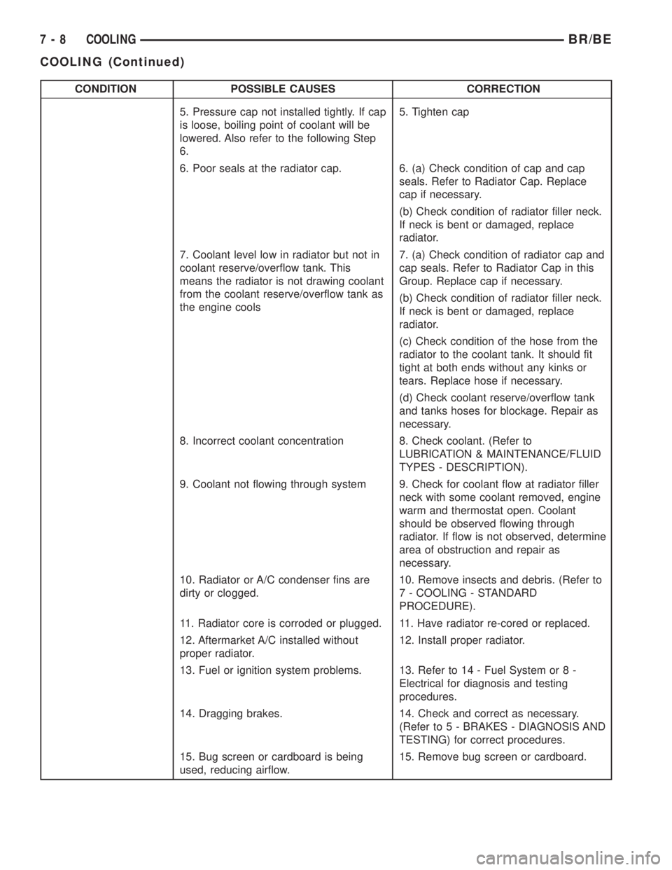
CONDITION POSSIBLE CAUSES CORRECTION
5. Pressure cap not installed tightly. If cap
is loose, boiling point of coolant will be
lowered. Also refer to the following Step
6.5. Tighten cap
6. Poor seals at the radiator cap. 6. (a) Check condition of cap and cap
seals. Refer to Radiator Cap. Replace
cap if necessary.
(b) Check condition of radiator filler neck.
If neck is bent or damaged, replace
radiator.
7. Coolant level low in radiator but not in
coolant reserve/overflow tank. This
means the radiator is not drawing coolant
from the coolant reserve/overflow tank as
the engine cools7. (a) Check condition of radiator cap and
cap seals. Refer to Radiator Cap in this
Group. Replace cap if necessary.
(b) Check condition of radiator filler neck.
If neck is bent or damaged, replace
radiator.
(c) Check condition of the hose from the
radiator to the coolant tank. It should fit
tight at both ends without any kinks or
tears. Replace hose if necessary.
(d) Check coolant reserve/overflow tank
and tanks hoses for blockage. Repair as
necessary.
8. Incorrect coolant concentration 8. Check coolant. (Refer to
LUBRICATION & MAINTENANCE/FLUID
TYPES - DESCRIPTION).
9. Coolant not flowing through system 9. Check for coolant flow at radiator filler
neck with some coolant removed, engine
warm and thermostat open. Coolant
should be observed flowing through
radiator. If flow is not observed, determine
area of obstruction and repair as
necessary.
10. Radiator or A/C condenser fins are
dirty or clogged.10. Remove insects and debris. (Refer to
7 - COOLING - STANDARD
PROCEDURE).
11. Radiator core is corroded or plugged. 11. Have radiator re-cored or replaced.
12. Aftermarket A/C installed without
proper radiator.12. Install proper radiator.
13. Fuel or ignition system problems. 13. Refer to 14 - Fuel System or 8 -
Electrical for diagnosis and testing
procedures.
14. Dragging brakes. 14. Check and correct as necessary.
(Refer to 5 - BRAKES - DIAGNOSIS AND
TESTING) for correct procedures.
15. Bug screen or cardboard is being
used, reducing airflow.15. Remove bug screen or cardboard.
7 - 8 COOLINGBR/BE
COOLING (Continued)
Page 447 of 2889
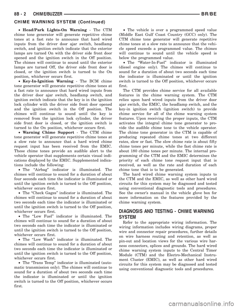
²Head/Park Lights-On Warning- The CTM
chime tone generator will generate repetitive chime
tones at a fast rate to announce that hard wired
inputs from the driver door ajar switch, headlamp
switch, and ignition switch indicate that the exterior
lamps are turned On with the driver side front door
opened and the ignition switch in the Off position.
The chimes will continue to sound until the exterior
lamps are turned Off, the driver side front door is
closed, or the ignition switch is turned to the On
position, whichever occurs first.
²Key-In-Ignition Warning- The BCM chime
tone generator will generate repetitive chime tones at
a fast rate to announce that hard wired inputs from
the driver door ajar switch, headlamp switch, and
ignition switch indicate that the key is in the ignition
lock cylinder with the driver side front door opened
and the ignition switch in the Off position. The
chimes will continue to sound until the key is
removed from the ignition lock cylinder, the driver
side front door is closed, or the ignition switch is
turned to the On position, whichever occurs first.
²Warning Chime Support- The CTM chime
tone generator will generate repetitive chime tones at
a slow rate to announce that a hard wired chime
request input has been received from the EMIC.
These chime tones provide an audible alert to the
vehicle operator that supplements certain visual indi-
cations displayed by the EMIC. Supplemented indica-
tions include the following:
²The ªAirbagº indicator is illuminated. The
chimes will continue to sound for a duration of about
four seconds each time the indicator is illuminated or
until the ignition switch is turned to the Off position,
whichever occurs first.
²The ªCheck Gagesº indicator is illuminated. The
chimes will continue to sound for a duration of about
two seconds each time the indicator is illuminated or
until the ignition switch is turned to the Off position,
whichever occurs first.
²The ªLow Fuelº indicator is illuminated. The
chimes will continue to sound for a duration of about
two seconds each time the indicator is illuminated or
until the ignition switch is turned to the Off position,
whichever occurs first.
²The ªLow Washº indicator is illuminated. The
chimes will continue to sound for a duration of about
two seconds each time the indicator is illuminated or
until the ignition switch is turned to the Off position,
whichever occurs first.
²The ªTrans Tempº indicator is illuminated (auto-
matic transmission only). The chimes will continue to
sound for a duration of about two seconds each time
the indicator is illuminated or until the ignition
switch is turned to the Off position, whichever occurs
first.²The vehicle is over a programmed speed value
(Middle East Gulf Coast Country (GCC) only). The
CTM chime tone generator will generate repetitive
chime tones at a slow rate to announce that the vehi-
cle speed exceeds a programmed value. The chimes
will continue to sound until the vehicle speed is
below the programmed value.
²The ªWater-In-Fuelº indicator is illuminated
(diesel engine only). The chimes will continue to
sound for a duration of about two seconds each time
the indicator is illuminated or until the ignition
switch is turned to the Off position, whichever occurs
first.
The CTM provides chime service for all available
features in the chime warning system. The CTM
relies upon hard wired inputs from the driver door
ajar switch, the EMIC, the headlamp switch, and the
key-in ignition switch (ignition switch) to provide
chime service for all of the chime warning system
features. Upon receiving the proper inputs, the CTM
activates the integral chime tone generator to pro-
vide the audible chime tone to the vehicle operator.
The chime tone generator in the CTM is capable of
producing repeated chime tones at two different
rates, slow or fast. The slow chime rate is about fifty
chime tones per minute, while the fast chime rate is
about 180 chime tones per minute. The internal pro-
gramming of the CTM and the EMIC determines the
priority of each chime tone request input that is
received, as well as the rate and duration of each
chime tone that is to be generated.
The hard wired chime warning system inputs to
the CTM and the EMIC, as well as other hard wired
circuits for this system may be diagnosed and tested
using conventional diagnostic tools and procedures.
See the owner's manual in the vehicle glove box for
more information on the features provided by the
chime warning system.
DIAGNOSIS AND TESTING - CHIME WARNING
SYSTEM
Refer to the appropriate wiring information. The
wiring information includes wiring diagrams, proper
wire and connector repair procedures, further details
on wire harness routing and retention, as well as
pin-out and location views for the various wire har-
ness connectors, splices and grounds. The hard wired
chime warning system inputs to the Central Timer
Module (CTM) and the Electro-Mechanical Instru-
ment Cluster (EMIC), as well as other hard wired
circuits for this system may be diagnosed and tested
using conventional diagnostic tools and procedures.
8B - 2 CHIME/BUZZERBR/BE
CHIME WARNING SYSTEM (Continued)
Page 492 of 2889
rosion or foreign material, then reassembled.
Following reassembly, check the voltage drop for the
battery cable connection and the battery cable again
to confirm repair.
When performing the voltage drop test, it is impor-
tant to remember that the voltage drop is giving an
indication of the resistance between the two points at
which the voltmeter probes are attached.EXAM-
PLE:When testing the resistance of the battery pos-
itive cable, touch the voltmeter leads to the battery
positive cable terminal clamp and to the battery pos-
itive cable eyelet terminal at the starter solenoid
B(+) terminal stud. If you probe the battery positive
terminal post and the battery positive cable eyelet
terminal at the starter solenoid B(+) terminal stud,
you are reading the combined voltage drop in the
battery positive cable terminal clamp-to-terminal
post connection and the battery positive cable.
VOLTAGE DROP TEST
WARNING: IF THE BATTERY SHOWS SIGNS OF
FREEZING, LEAKING, LOOSE POSTS, OR LOW
ELECTROLYTE LEVEL, DO NOT TEST, ASSIST-
BOOST, OR CHARGE. THE BATTERY MAY ARC
INTERNALLY AND EXPLODE. PERSONAL INJURY
AND/OR VEHICLE DAMAGE MAY RESULT.
WARNING: EXPLOSIVE HYDROGEN GAS FORMS IN
AND AROUND THE BATTERY. DO NOT SMOKE,
USE FLAME, OR CREATE SPARKS NEAR THE BAT-
TERY. PERSONAL INJURY AND/OR VEHICLE DAM-
AGE MAY RESULT.
WARNING: THE BATTERY CONTAINS SULFURIC
ACID, WHICH IS POISONOUS AND CAUSTIC. AVOID
CONTACT WITH THE SKIN, EYES, OR CLOTHING.
IN THE EVENT OF CONTACT, FLUSH WITH WATER
AND CALL A PHYSICIAN IMMEDIATELY. KEEP OUT
OF THE REACH OF CHILDREN.
WARNING: IF THE BATTERY IS EQUIPPED WITH
REMOVABLE CELL CAPS, BE CERTAIN THAT EACH
OF THE CELL CAPS IS IN PLACE AND TIGHT
BEFORE THE BATTERY IS RETURNED TO SER-
VICE. PERSONAL INJURY AND/OR VEHICLE DAM-
AGE MAY RESULT FROM LOOSE OR MISSING
CELL CAPS.
WARNING: MODELS EQUIPPED WITH THE DIESEL
ENGINE OPTION ALSO HAVE AN AUTOMATIC
SHUTDOWN (ASD) RELAY LOCATED IN THE
POWER DISTRIBUTION CENTER (PDC), IN THE
ENGINE COMPARTMENT. HOWEVER, REMOVAL OFTHE ASD RELAY MAY NOT PREVENT THE DIESEL
ENGINE FROM STARTING. BE CERTAIN TO ALSO
DISCONNECT THE FUEL SHUTDOWN SOLENOID
WIRE HARNESS CONNECTOR ON MODELS WITH A
DIESEL ENGINE. FAILURE TO DO SO MAY RESULT
IN PERSONAL INJURY.
The following operation will require a voltmeter
accurate to 1/10 (0.10) volt. Before performing this
test, be certain that the following procedures are
accomplished:
²The battery is fully-charged and load tested.
Refer toBattery Chargingin the index of this ser-
vice manual for the location of the proper battery
charging procedures. Refer toBatteryin the index of
this service manual for the location of the battery
diagnosis and testing procedures, including the
proper battery load test procedures.
²Fully engage the parking brake.
²If the vehicle is equipped with an automatic
transmission, place the gearshift selector lever in the
Park position. If the vehicle is equipped with a man-
ual transmission, place the gearshift selector lever in
the Neutral position and block the clutch pedal in the
fully depressed position.
²Verify that all lamps and accessories are turned
off.
²To prevent a gasoline engine from starting,
remove the Automatic ShutDown (ASD) relay. The
ASD relay is located in the Power Distribution Cen-
ter (PDC), in the engine compartment. See the fuse
and relay layout label affixed to the underside of the
PDC cover for ASD relay identification and location.
To prevent a diesel engine from starting, disconnect
the fuel shutdown solenoid wire harness connector
(Fig. 21).
(1) Connect the positive lead of the voltmeter to
the battery negative terminal post. Connect the neg-
ative lead of the voltmeter to the battery negative
cable terminal clamp (Fig. 22). Rotate and hold the
ignition switch in the Start position. Observe the
voltmeter. If voltage is detected, correct the poor con-
nection between the battery negative cable terminal
clamp and the battery negative terminal post.
NOTE: If the vehicle is equipped with a dual battery
system, Step 1 must be performed twice, once for
each battery.
(2) Connect the positive lead of the voltmeter to
the battery positive terminal post. Connect the nega-
tive lead of the voltmeter to the battery positive cable
terminal clamp (Fig. 23). Rotate and hold the ignition
switch in the Start position. Observe the voltmeter. If
voltage is detected, correct the poor connection
between the battery positive cable terminal clamp
and the battery positive terminal post.
BR/BEBATTERY SYSTEM 8F - 21
BATTERY CABLE (Continued)
Page 538 of 2889

IGNITION CONTROL
TABLE OF CONTENTS
page page
IGNITION CONTROL
DESCRIPTION............................1
OPERATION.............................1
SPECIFICATIONS.........................2
AUTOMATIC SHUT DOWN RELAY
DESCRIPTION............................3
OPERATION.............................3
DIAGNOSIS AND TESTING..................3
ASD AND FUEL PUMP RELAYS.............3
REMOVAL...............................4
INSTALLATION............................5
CAMSHAFT POSITION SENSOR
DESCRIPTION............................5
OPERATION.............................5
REMOVAL...............................7
INSTALLATION............................8
DISTRIBUTOR
DESCRIPTION...........................10
OPERATION.............................11
REMOVAL..............................11
INSTALLATION...........................11
DISTRIBUTOR CAP
DIAGNOSIS AND TESTING.................12
DISTRIBUTOR CAP.....................12DISTRIBUTOR ROTOR
DIAGNOSIS AND TESTING.................13
DISTRIBUTOR ROTOR...................13
IGNITION COIL
DESCRIPTION...........................13
OPERATION.............................14
REMOVAL..............................14
INSTALLATION...........................15
SPARK PLUG
DESCRIPTION...........................16
OPERATION.............................16
DIAGNOSIS AND TESTING.................16
SPARK PLUG CONDITIONS...............16
REMOVAL..............................18
CLEANING..............................19
INSTALLATION...........................19
SPARK PLUG CABLE
DESCRIPTION...........................19
OPERATION.............................19
DIAGNOSIS AND TESTING.................19
SPARK PLUG CABLES...................19
REMOVAL..............................20
INSTALLATION...........................20
IGNITION CONTROL
DESCRIPTION - 8.0L V-10
The ignition system used on the 8.0L V±10 engine
does not use a conventional mechanical distributor.
The system will be referred to as a distributor-less
ignition system.
DESCRIPTION - V-6/V-8
The ignition systems used on the 3.9L V-6, the
5.2L V-8 and the 5.9L V-8 are basically identical.
OPERATION - 8.0L V-10
The ignition coils are individually fired, but each
coil is a dual output. Refer to Ignition Coil for addi-
tional information.
The ignition system is controlled by the Powertrain
Control Module (PCM) on all engines.
The ignition system consists of:
²Spark Plugs
²Ignition Coil packs containing individual coils²Secondary Ignition Cables
²Powertrain Control Module (PCM)
²Also to be considered part of the ignition system
are certain inputs from the Crankshaft Position,
Camshaft Position, Throttle Position and MAP Sen-
sors
OPERATION - V-6/V-8
The ignition system is controlled by the Powertrain
Control Module (PCM) on all engines.
The ignition system consists of:
²Spark Plugs
²Ignition Coil
²Secondary Ignition Cables
²Distributor (contains rotor and camshaft position
sensor)
²Powertrain Control Module (PCM)
²Also to be considered part of the ignition system
are certain inputs from the Crankshaft Position,
Camshaft Position, Throttle Position and MAP Sen-
sors
BR/BEIGNITION CONTROL 8I - 1
Page 544 of 2889

REMOVAL - DIESEL
The camshaft position sensor (CMP) is located
below the fuel injection pump (Fig. 9). It is attached
to the back of the timing gear cover housing.
(1) Disconnect both negative cables from both bat-
teries.
(2) Clean area around CMP.
(3) Disconnect electrical at CMP (Fig. 9).
(4) Remove CMP mounting bolt. Bolt head is
female-hex (Fig. 10).
(5) Remove CMP from engine by twisting and pull-
ing straight back.
(6) Discard CMP o-ring (Fig. 10).
REMOVAL - 3.9L/5.2L/5.9L
The camshaft position sensor is located in the dis-
tributor (Fig. 11).
Distributor removal is not necessary to remove
camshaft position sensor.
(1) Remove air cleaner assembly.
(2) Disconnect negative cable from battery.
(3) Remove distributor cap from distributor (two
screws).
(4) Disconnect camshaft position sensor wiring
harness from main engine wiring harness.
(5) Remove distributor rotor from distributor shaft.(6) Lift the camshaft position sensor assembly
from the distributor housing (Fig. 11).
Fig. 8 CMP Sensor OperationÐ8.0L V-10 Engine
1 - CAM DRIVE GEAR
2 - LOW MACHINED AREA
3 - HIGH MACHINED AREA
4 - CAMSHAFT POSITION SENSOR
5 - AIR GAP
Fig. 9 CMP Location - Diesel
1 - CAMSHAFT POSITION SENSOR (CMP)
2 - BOTTOM OF FUEL INJECTION PUMP
Fig. 10 CMP R/I - Diesel
1 - GEAR HOUSING
2 - O-RING
3 - CMP SENSOR
4 - CMP HEX HEAD BOLT
BR/BEIGNITION CONTROL 8I - 7
CAMSHAFT POSITION SENSOR (Continued)
Page 548 of 2889

OPERATION
The camshaft position sensor provides fuel injec-
tion synchronization and cylinder identification.
The distributor does not have built in centrifugal
or vacuum assisted advance. Base ignition timing
and all timing advance is controlled by the Power-
train Control Module (PCM). Because ignition timing
is controlled by the PCM,base ignition timing is
not adjustable.
The distributor is held to the engine in the conven-
tional method using a holddown clamp and bolt.
Although the distributor can be rotated, it will
have no effect on ignition timing.
All distributors contain an internal oil seal that
prevents oil from entering the distributor housing.
The seal is not serviceable.
REMOVAL
CAUTION: Base ignition timing is not adjustable on
any engine. Distributors do not have built in centrif-
ugal or vacuum assisted advance. Base ignition
timing and timing advance are controlled by the
Powertrain Control Module (PCM). Because a con-
ventional timing light can not be used to adjust dis-
tributor position after installation, note position of
distributor before removal.
(1) Remove air cleaner assembly.
(2) Disconnect negative cable from battery.
(3) Remove distributor cap from distributor (two
screws).
(4) Mark the position of distributor housing in
relationship to engine or dash panel. This is done to
aid in installation.(5) Before distributor is removed, the number one
cylinder must be brought to the Top Dead Center
(TDC) firing position.
(6) Attach a socket to the Crankshaft Vibration
Damper mounting bolt.
(7) Slowly rotate engine clockwise, as viewed from
front, until indicating mark on crankshaft vibration
damper is aligned to 0 degree (TDC) mark on timing
chain cover (Fig. 18).
(8) The distributor rotor should now be aligned to
the CYL. NO. 1 alignment mark (stamped) into the
camshaft position sensor (Fig. 19). If not, rotate the
crankshaft through another complete 360 degree
turn. Note the position of the number one cylinder
spark plug cable (on the cap) in relation to rotor.
Rotor should now be aligned to this position.
(9) Disconnect camshaft position sensor wiring
harness from main engine wiring harness.
(10) Remove distributor rotor from distributor
shaft.
(11) Remove distributor holddown clamp bolt and
clamp (Fig. 20). Remove distributor from vehicle.
CAUTION: Do not crank engine with distributor
removed. Distributor/crankshaft relationship will be
lost.
INSTALLATION
If engine has been cranked while distributor is
removed, establish the relationship between distribu-
tor shaft and number one piston position as follows:
Rotate crankshaft in a clockwise direction, as
viewed from front, until number one cylinder piston
is at top of compression stroke (compression should
be felt on finger with number one spark plug
Fig. 17 Distributor and Camshaft Position Sensor
1 - SYNC SIGNAL GENERATOR
2 - CAMSHAFT POSITION SENSOR
3 - PULSE RING
4 - DISTRIBUTOR ASSEMBLY
Fig. 18 Damper-To-Cover Alignment MarksÐTypical
1 - ALIGNMENT MARK
2 - TIMING CHAIN COVER MARKS
3 - CRANKSHAFT VIBRATION DAMPER
BR/BEIGNITION CONTROL 8I - 11
DISTRIBUTOR (Continued)