2001 DODGE RAM power steering
[x] Cancel search: power steeringPage 1 of 2889

GROUP TAB LOCATOR
Introduction
0Lubrication & Maintenance
2Suspension
3Differential & Driveline
5Brakes
7Cooling
8AAudio
8BChime/Buzzer
8EElectronic Control Modules
8FEngine Systems
8GHeated Systems
8HHorn
8IIgnition Control
8JInstrument Cluster
8LLamps
8MMessage Systems
8NPower Systems
8ORestraints
8PSpeed Control
8QVehicle Theft Security
8RWipers/Washers
8WWiring
9Engine
11Exhaust System
13Frame & Bumpers
14Fuel System
19Steering
21Transmission/Transaxle
22Tires/Wheels
23Body
24Heating & Air Conditioning
25Emissions Control Systems
30New Vehicle Preparation
Component and System Index
Service Manual Comment Forms (Rear of Manual)
Page 19 of 2889
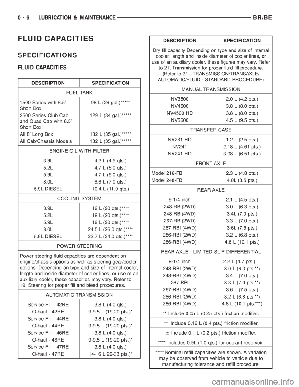
FLUID CAPACITIES
SPECIFICATIONS
FLUID CAPACITIES
DESCRIPTION SPECIFICATION
FUEL TANK
1500 Series with 6.5'
Short Box98 L (26 gal.)*****
2500 Series Club Cab
and Quad Cab with 6.5'
Short Box129 L (34 gal.)*****
All 8' Long Box 132 L (35 gal.)*****
All Cab/Chassis Models 132 L (35 gal.)*****
ENGINE OIL WITH FILTER
3.9L 4.2 L (4.5 qts.)
5.2L 4.7 L (5.0 qts.)
5.9L 4.7 L (5.0 qts.)
8.0L 6.6 L (7.0 qts.)
5.9L DIESEL 10.4 L (11.0 qts.)
COOLING SYSTEM
3.9L 19 L (20 qts.)****
5.2L 19 L (20 qts.)****
5.9L 19 L (20 qts.)****
8.0L 24.5 L (26.0 qts.)****
5.9L DIESEL 22.7 L (24.0 qts.)****
POWER STEERING
Power steering fluid capacities are dependent on
engine/chassis options as well as steering gear/cooler
options. Depending on type and size of internal cooler,
length and inside diameter of cooler lines, or use of an
auxiliary cooler, these capacities may vary. Refer to
19, Steering for proper fill and bleed procedures.
AUTOMATIC TRANSMISSION
Service Fill - 42RE 3.8 L (4.0 qts.)
O-haul - 42RE 9-9.5 L (19-20 pts.)*
Service Fill - 44RE 3.8 L (4.0 qts.)
O-haul - 44RE 9-9.5 L (19-20 pts.)*
Service Fill - 46RE 3.8 L (4.0 qts.)
O-haul - 46RE 9-9.5 L (19-20 pts.)*
Service Fill - 47RE 3.8 L (4.0 qts.)
O-haul - 47RE 14-16 L 29-33 pts.)*
DESCRIPTION SPECIFICATION
Dry fill capacity Depending on type and size of internal
cooler, length and inside diameter of cooler lines, or
use of an auxiliary cooler, these figures may vary. Refer
to 21, Transmission for proper fluid fill procedure.
(Refer to 21 - TRANSMISSION/TRANSAXLE/
AUTOMATIC/FLUID - STANDARD PROCEDURE)
MANUAL TRANSMISSION
NV3500 2.0 L (4.2 pts.)
NV4500 3.8 L (8.0 pts.)
NV4500 HD 3.8 L (8.0 pts.)
NV5600 4.5 L (9.5 pts.)
TRANSFER CASE
NV231 HD 1.2 L (2.5 pts.)
NV241 2.18 L (4.61 pts.)
NV241 HD 3.08 L (6.51 pts.)
FRONT AXLE
Model 216-FBI 2.3 L (4.8 pts.)
Model 248-FBI 4.0L (8.5 pts.)
REAR AXLE
9-1/4 inch 2.1 L (4.5 pts.)
248-RBI(2WD) 3.0 L (6.3 pts.)
248-RBI(4WD) 3.4L (7.0 pts.)
267-RBI(2WD) 3.3 L (7.0 pts.)
267-RBI (4WD) 3.6L (7.5 pts.)
286-RBI (2WD) 3.2 L (6.8 pts.)
286-RBI (4WD) 4.8 L (10.1 pts.)
REAR AXLEÐLIMITED SLIP DIFFERENTIAL
9-1/4 inch 2.2 L (4.7 pts.)6
248-RBI (2WD) 3.0 L (6.3 pts.**)
248-RBI (4WD) 3.4 L (7.0 pts.)
267-RBI 3.3 L (7.0 pts.**)
267-RBI (4WD) 3.6 L (7.5 pts.)
286-RBI (2WD) 3.2 L (6.8 pts.**)
286-RBI (4WD) 4.8 L (10.1 pts.***)
** Include 0.05 L (0.25 pts.) friction modifier.
*** Include 0.19 L (0.4 pts.) friction modifier.
6Include 0.1 L (0.2 pts.) friction modifier.
**** Includes 0.9L (1.0 qts.) for coolant reservoir.
*****Nominal refill capacities are shown. A variation
may be observed from vehicle to vehicle due to
manufacturing tolerance and refill procedure.
0 - 6 LUBRICATION & MAINTENANCEBR/BE
Page 20 of 2889
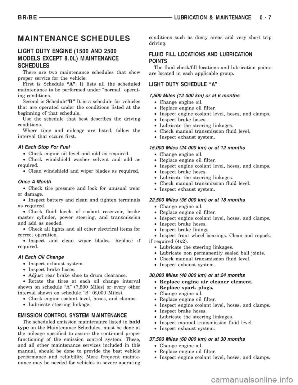
MAINTENANCE SCHEDULES
LIGHT DUTY ENGINE (1500 AND 2500
MODELS EXCEPT 8.0L) MAINTENANCE
SCHEDULES
There are two maintenance schedules that show
proper service for the vehicle.
First is ScheduleªAº. It lists all the scheduled
maintenance to be performed under ªnormalº operat-
ing conditions.
Second is ScheduleªBºIt is a schedule for vehicles
that are operated under the conditions listed at the
beginning of that schedule.
Use the schedule that best describes the driving
conditions.
Where time and mileage are listed, follow the
interval that occurs first.
At Each Stop For Fuel
²Check engine oil level and add as required.
²Check windshield washer solvent and add as
required.
²Clean windshield and wiper blades as required.
Once A Month
²Check tire pressure and look for unusual wear
or damage.
²Inspect battery and clean and tighten terminals
as required.
²Check fluid levels of coolant reservoir, brake
master cylinder, power steering, and transmission
and add as needed.
²Check all lights and all other electrical items for
correct operation.
²Inspect and clean wiper blades. Replace if
required.
At Each Oil Change
²Inspect exhaust system.
²Inspect brake hoses.
²Adjust rear brake shoe to drum clearance.
²Rotate the tires at each oil change interval
shown on schedule ªAº (7,500 Miles) or every other
interval shown on schedule ªBº (6,000 Miles).
²Check engine coolant level, hoses, and clamps.
²Lubricate steering linkage.
EMISSION CONTROL SYSTEM MAINTENANCE
The scheduled emission maintenance listed inbold
typeon the Maintenance Schedules, must be done at
the mileage specified to assure the continued proper
functioning of the emission control system. These,
and all other maintenance services included in this
manual, should be done to provide the best vehicle
performance and reliability. More frequent mainte-
nance may be needed for vehicles in severe operatingconditions such as dusty areas and very short trip
driving.
FLUID FILL LOCATIONS AND LUBRICATION
POINTS
The fluid check/fill locations and lubrication points
are located in each applicable group.
LIGHT DUTY SCHEDULE ªAº
7,500 Miles (12 000 km) or at 6 months
²Change engine oil.
²Replace engine oil filter.
²Inspect engine coolant level, hoses, and clamps.
²Inspect brake hoses.
²Lubricate the steering linkages.
²Check manual transmission fluid level.
²Inspect exhaust system.
15,000 Miles (24 000 km) or at 12 months
²Change engine oil.
²Replace engine oil filter.
²Inspect engine coolant level, hoses, and clamps.
²Inspect brake hoses.
²Lubricate the steering linkages.
²Check manual transmission fluid level.
²Inspect exhaust system.
22,500 Miles (36 000 km) or at 18 months
²Change engine oil.
²Replace engine oil filter.
²Inspect engine coolant level, hoses, and clamps.
²Inspect brake hoses.
²Inspect brake linings.
²Inspect front wheel bearings. Clean and repack,
if required (4x2).
²Lubricate the steering linkages.
²Lubricate non permanently sealed ball joints.
²Check manual transmission fluid level.
²Inspect exhaust system.
30,000 Miles (48 000 km) or at 24 months
²Replace engine air cleaner element.
²Replace spark plugs.
²Change engine oil.
²Replace engine oil filter.
²Inspect engine coolant level, hoses, and clamps.
²Inspect brake hoses.
²Lubricate the steering linkages.
²Inspect manual transmission fluid level.
²Inspect exhaust system.
37,500 Miles (60 000 km) or at 30 months
²Change engine oil.
²Replace engine oil filter.
²Inspect engine coolant level, hoses, and clamps.
BR/BELUBRICATION & MAINTENANCE 0 - 7
Page 26 of 2889
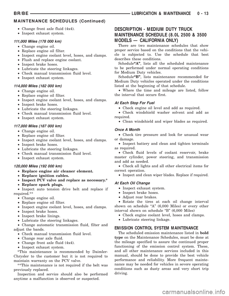
²Change front axle fluid (4x4).
²Inspect exhaust system.
111,000 Miles (178 000 km)
²Change engine oil.
²Replace engine oil filter.
²Inspect engine coolant level, hoses, and clamps.
²Flush and replace engine coolant.
²Inspect brake hoses.
²Lubricate the steering linkages.
²Check manual transmission fluid level.
²Inspect exhaust system.
114,000 Miles (182 000 km)
²Change engine oil.
²Replace engine oil filter.
²Inspect engine coolant level, hoses, and clamps.
²Inspect brake hoses.
²Lubricate the steering linkages.
²Check manual transmission fluid level.
²Inspect exhaust system.
117,000 Miles (187 000 km)
²Change engine oil.
²Replace engine oil filter.
²Inspect engine coolant level, hoses, and clamps.
²Inspect brake hoses.
²Lubricate the steering linkages.
²Check manual transmission fluid level.
²Inspect exhaust system.
120,000 Miles (192 000 km)
²Replace engine air cleaner element.
²Replace ignition cables.
²
Inspect PCV valve and replace as necessary.*
²Replace spark plugs.
²Inspect auto tension drive belt and replace if
required.**
²Change engine oil.
²Replace engine oil filter.
²Inspect engine coolant level, hoses, and clamps.
²Inspect brake hoses.
²Inspect brake linings.
²Lubricate the steering linkages.
²Change automatic transmission fluid, filter and
adjust the bands.
²Check manual transmission fluid level.
²Change rear axle fluid.
²Change front axle fluid (4x4).
²Inspect exhaust system.
*This maintenance is recommended by Daimler-
Chrysler to the customer but it is not required to
maintain warranty on the PCV valve.
**This maintenance is not required if the belt was
previously replaced.
Inspection and service should also be performed
anytime a malfunction is observed or suspected.
DESCRIPTION - MEDIUM DUTY TRUCK
MAINTENANCE SCHEDULE (8.0L 2500 & 3500
MODELS Ð CALIFORNIA ONLY)
There are two maintenance schedules that show
proper service based on the conditions that the vehi-
cle is subjected to. Use the schedule that best
describes these conditions.
ScheduleªAº, lists all the scheduled maintenance
to be performed under normal operating conditions
for Medium Duty vehicles.
ScheduleªBº, lists maintenance recommended for
Medium Duty vehicles operated under the conditions
listed at the beginning of that schedule.
²Where the time and mileage are listed, follow
the interval that occurs first.
At Each Stop For Fuel
²Check engine oil level and add as required.
²Check windshield washer solvent and add as
required.
²Clean windshield and wiper blades as required.
Once A Month
²Check tire pressure and look for unusual wear
or damage.
²Inspect battery and clean and tighten terminals
as required.
²Check fluid levels of coolant reservoir, brake
master cylinder, power steering, and transmission
and add as needed.
²Check all lights and all other electrical items for
correct operation.
²
Inspect and clean wiper blades. Replace if required.
At Each Oil Change
²Inspect exhaust system.
²Inspect brake hoses.
²Adjust rear brakes.
²Rotate the tires at each oil change interval
shown on schedule ªAº (6,000 Miles) or every other
interval shown on schedule ªBº (6,000 Miles)
²Check engine coolant level, hoses and clamps.
²Lubricate steering linkage.
EMISSION CONTROL SYSTEM MAINTENANCE
The scheduled emission maintenance listed inbold
typeon the Maintenance Schedules, must be done at
the mileage specified to assure the continued proper
functioning of the emission control system. These,
and all other maintenance services included in this
manual, should be done to provide the best vehicle
performance and reliability. More frequent mainte-
nance may be needed for vehicles in severe operating
conditions such as dusty areas and very short trip
driving.
BR/BELUBRICATION & MAINTENANCE 0 - 13
MAINTENANCE SCHEDULES (Continued)
Page 30 of 2889
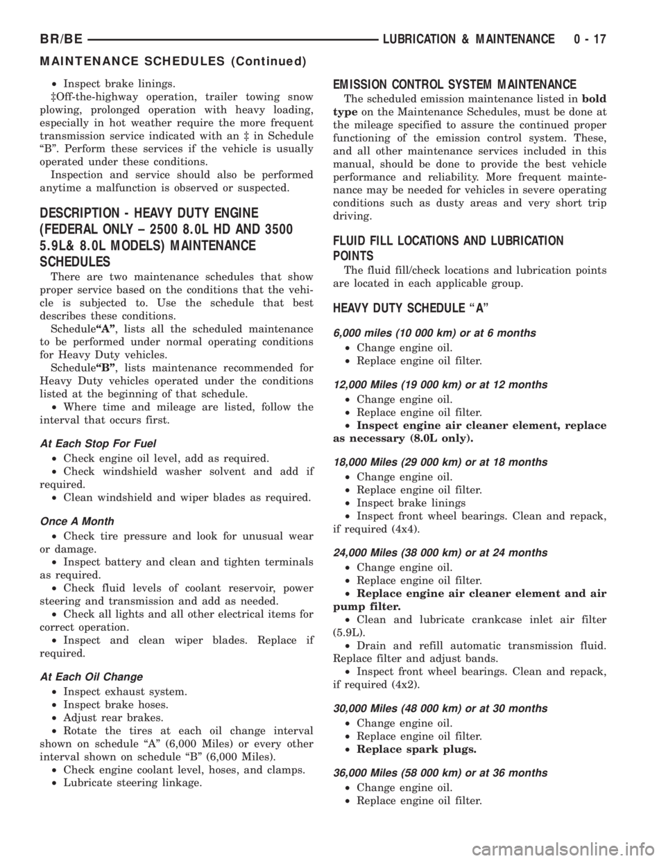
²Inspect brake linings.
³Off-the-highway operation, trailer towing snow
plowing, prolonged operation with heavy loading,
especially in hot weather require the more frequent
transmission service indicated with an ³ in Schedule
ªBº. Perform these services if the vehicle is usually
operated under these conditions.
Inspection and service should also be performed
anytime a malfunction is observed or suspected.
DESCRIPTION - HEAVY DUTY ENGINE
(FEDERAL ONLY ± 2500 8.0L HD AND 3500
5.9L& 8.0L MODELS) MAINTENANCE
SCHEDULES
There are two maintenance schedules that show
proper service based on the conditions that the vehi-
cle is subjected to. Use the schedule that best
describes these conditions.
ScheduleªAº, lists all the scheduled maintenance
to be performed under normal operating conditions
for Heavy Duty vehicles.
ScheduleªBº, lists maintenance recommended for
Heavy Duty vehicles operated under the conditions
listed at the beginning of that schedule.
²Where time and mileage are listed, follow the
interval that occurs first.
At Each Stop For Fuel
²Check engine oil level, add as required.
²Check windshield washer solvent and add if
required.
²Clean windshield and wiper blades as required.
Once A Month
²Check tire pressure and look for unusual wear
or damage.
²Inspect battery and clean and tighten terminals
as required.
²Check fluid levels of coolant reservoir, power
steering and transmission and add as needed.
²Check all lights and all other electrical items for
correct operation.
²Inspect and clean wiper blades. Replace if
required.
At Each Oil Change
²Inspect exhaust system.
²Inspect brake hoses.
²Adjust rear brakes.
²Rotate the tires at each oil change interval
shown on schedule ªAº (6,000 Miles) or every other
interval shown on schedule ªBº (6,000 Miles).
²Check engine coolant level, hoses, and clamps.
²Lubricate steering linkage.
EMISSION CONTROL SYSTEM MAINTENANCE
The scheduled emission maintenance listed inbold
typeon the Maintenance Schedules, must be done at
the mileage specified to assure the continued proper
functioning of the emission control system. These,
and all other maintenance services included in this
manual, should be done to provide the best vehicle
performance and reliability. More frequent mainte-
nance may be needed for vehicles in severe operating
conditions such as dusty areas and very short trip
driving.
FLUID FILL LOCATIONS AND LUBRICATION
POINTS
The fluid fill/check locations and lubrication points
are located in each applicable group.
HEAVY DUTY SCHEDULE ªAº
6,000 miles (10 000 km) or at 6 months
²Change engine oil.
²Replace engine oil filter.
12,000 Miles (19 000 km) or at 12 months
²Change engine oil.
²Replace engine oil filter.
²Inspect engine air cleaner element, replace
as necessary (8.0L only).
18,000 Miles (29 000 km) or at 18 months
²Change engine oil.
²Replace engine oil filter.
²Inspect brake linings
²Inspect front wheel bearings. Clean and repack,
if required (4x4).
24,000 Miles (38 000 km) or at 24 months
²Change engine oil.
²Replace engine oil filter.
²Replace engine air cleaner element and air
pump filter.
²Clean and lubricate crankcase inlet air filter
(5.9L).
²Drain and refill automatic transmission fluid.
Replace filter and adjust bands.
²Inspect front wheel bearings. Clean and repack,
if required (4x2).
30,000 Miles (48 000 km) or at 30 months
²Change engine oil.
²Replace engine oil filter.
²Replace spark plugs.
36,000 Miles (58 000 km) or at 36 months
²Change engine oil.
²Replace engine oil filter.
BR/BELUBRICATION & MAINTENANCE 0 - 17
MAINTENANCE SCHEDULES (Continued)
Page 35 of 2889
99,000 Miles (156 000 km)
²Change engine oil.
²Replace engine oil filter.
²Lubricate tie rod ends every 3,000 miles (5 000
km).
²Inspect front wheel bearings (4x2).
102,000 Miles (163 000 km)
²Change engine oil.
²Replace engine oil filter.
²Lubricate tie rod ends every 3,000 miles (5 000
km).
²Inspect front wheel bearings (4x4).
105,000 Miles (168 000 km)
²Change engine oil.
²Replace engine oil filter.
²Lubricate tie rod ends every 3,000 miles (5 000
km).
108,000 Miles (173 000 km)
²Change engine oil.
²Replace engine oil filter.
²Inspect engine air cleaner element and air
pump filter, replace as necessary.
²Drain and refill automatic transmission fluid.
Replace filter and adjust bands.³
²Drain and refill transfer case fluid (4x4).
²Change rear axle fluid.
²Change front axle fluid (4x4).
²Inspect brake linings.
²Flush and replace engine coolant if it has been
30,000 miles (48 000 km) since last change.
²Lubricate tie rod ends every 3,000 miles (5 000
km).
²Inspect front wheel bearings (4x4).
²Inspect front wheel bearings (4x2).
*Requires Service Reminder Indicator Light. If so
equipped, these parts are to be replaced at the indi-
cated mileage or when the service reminder indicator
light remains on continuously with the key in the
ªONº position, whichever occurs first.
³Off-the-highway operation, trailer towing, snow
plowing, prolonged operation with heavy loading,
especially in hot weather require the more frequent
transmission service indicated witha³inSchedule
ªBº. Perform these services if you usually operate
your Ram Truck under these conditions.
Inspection and service should also be performed
anytime a malfunction is observed or suspected.
DESCRIPTION - MAINTENANCE SCHEDULES
Ð 24±VALVE CUMMINS TURBO DIESEL
There are two maintenance schedules that show
proper service for the vehicle.First is ScheduleªA.ºIt lists all the scheduled
maintenance to be performed under ªnormalº operat-
ing conditions.
Second is ScheduleªB.ºIt is a schedule for vehicles
that are operated under the conditions listed at the
beginning of that schedule.
Use the schedule that best describes the driving
conditions.
Where time and mileage are listed, follow the
interval that occurs first.
At Each Stop For Fuel
²Check engine oil level and add as required.
²Check windshield washer solvent and add if
required.
²Clean windshield and wiper blades as required.
²Drain water from fuel filter.
Once A Month
²Check tire pressure and look for unusual wear
or damage.
²Inspect battery and clean and tighten terminals
as required.
²Check fluid levels of coolant reservoir, brake
master cylinder, power steering, and transmission.
Add fluid as required.
²Check all lights and all other electrical items for
correct operation.
²Check Filter Mindery. Replace air cleaner
element if necessary.
²Inspect and clean wiper blades. Replace if
required.
At Each Oil Change
²Inspect exhaust system.
²Inspect brake hoses.
²Adjust rear brakes.
²Rotate the tires at each oil change interval
shown at 7, 5000 miles (12 000 km) on schedule ªAº
or every other interval shown at 7,500 miles (12 000
km) on schedule ªBº.
²Check engine coolant level, hoses, and clamps.
²Lubricate steering linkage.
²Drain crankcase breather canister (if equipped).
EMISSION CONTROL SYSTEM MAINTENANCE
The scheduled emission maintenance listed inbold
typeon the Maintenance Schedules, must be done at
the mileage specified to assure the continued proper
functioning of the emission control system. These,
and all other maintenance services included in this
manual, should be done to provide the best vehicle
performance and reliability. More frequent mainte-
nance may be needed for vehicles in severe operating
conditions such as dusty areas and very short trip
driving.
0 - 22 LUBRICATION & MAINTENANCEBR/BE
MAINTENANCE SCHEDULES (Continued)
Page 85 of 2889
FRONT AXLE - 216FBI
TABLE OF CONTENTS
page page
FRONT AXLE - 216FBI
DESCRIPTION...........................12
OPERATION.............................12
DIAGNOSIS AND TESTING.................13
AXLE................................13
REMOVAL..............................16
INSTALLATION...........................17
ADJUSTMENTS..........................17
SPECIFICATIONS........................25
SPECIAL TOOLS.........................25
AXLE SHAFTS
REMOVAL..............................28
INSTALLATION...........................28
AXLE SHAFTS - INTERMEDIATE
REMOVAL..............................28
INSTALLATION...........................28
AXLE SHAFT SEALS
REMOVAL..............................29
INSTALLATION...........................29
AXLE VACUUM MOTOR
DESCRIPTION...........................29
OPERATION.............................30
DIAGNOSIS AND TESTING.................31VACUUM MOTOR.......................31
REMOVAL..............................33
DISASSEMBLY...........................33
ASSEMBLY.............................33
INSTALLATION...........................33
SINGLE CARDAN UNIVERSAL JOINTS
REMOVAL..............................33
INSTALLATION...........................34
PINION SEAL
REMOVAL..............................34
INSTALLATION...........................34
DIFFERENTIAL
REMOVAL..............................36
DISASSEMBLY...........................36
ASSEMBLY.............................37
INSTALLATION...........................37
DIFFERENTIAL CASE BEARINGS
REMOVAL..............................39
INSTALLATION...........................39
PINION GEAR/RING GEAR
REMOVAL..............................40
INSTALLATION...........................42
FRONT AXLE - 216FBI
DESCRIPTION
The housing for the 216 Front Beam-design Iron
(FBI) axles consists of an iron center casting with
tubes on each side. The tubes are pressed into and
welded to the differential housing.
The integral type housing, hypoid gear design has
the centerline of the pinion set below the centerline
of the ring gear.
The axle has a vent used to relieve internal pres-
sure caused by lubricant vaporization and internal
expansion.
The axles are equipped with semi-floating axle
shafts, meaning that loads are supported by the hub
bearings. The axle shafts are retained by nuts at the
hub bearings. The hub bearings are bolted to the
steering knuckle at the outboard end of the axle tube
yoke. The hub bearings are serviced as an assembly.
The axles are equipped with ABS brake sensors.
The sensors are attached to the knuckle assemblies
and the tone rings are pressed onto the axle shaft.
Use care when removing axle shafts as NOT to
damage the tone wheel or the sensor.The stamped steel cover provides a means for
inspection and servicing the differential.
The 216 axle have the assembly part number and
gear ratio listed on a tag. The tag is attached to the
housing cover by one of the cover bolts. Build date
identification codes are stamped on the cover side of
a axle tube.
The differential case is a one-piece design. The dif-
ferential pinion mate shaft is retained with a roll
pin. Differential bearing preload and ring gear back-
lash is adjusted by the use of shims. The shims are
located between the differential bearing cones and
case. Pinion bearing preload is set and maintained by
the use of a collapsible spacer.
The axle differential covers can be used for identi-
fication of the axle (Fig. 1). A tag is also attached to
the cover.
OPERATION
The axle receives power from the transfer case
through the front propeller shaft. The front propeller
shaft is connected to the pinion gear which rotates
the differential through the gear mesh with the ring
gear bolted to the differential case. The engine power
is transmitted to the axle shafts through the pinion
3 - 12 FRONT AXLE - 216FBIBR/BE
Page 118 of 2889
FRONT AXLE - 248FBI
TABLE OF CONTENTS
page page
FRONT AXLE - 248FBI
DESCRIPTION...........................45
OPERATION.............................45
DIAGNOSIS AND TESTING.................46
AXLE................................46
REMOVAL..............................50
INSTALLATION...........................50
ADJUSTMENTS..........................50
SPECIFICATIONS........................58
SPECIAL TOOLS.........................58
AXLE SHAFTS
REMOVAL..............................60
INSTALLATION...........................60
AXLE SHAFTS - INTERMEDIATE
REMOVAL..............................60
INSTALLATION...........................61
AXLE SHAFT SEALS
REMOVAL..............................61
INSTALLATION...........................61
AXLE VACUUM MOTOR
DESCRIPTION...........................62
OPERATION.............................62
DIAGNOSIS AND TESTING.................63VACUUM MOTOR.......................63
REMOVAL..............................65
DISASSEMBLY...........................65
ASSEMBLY.............................65
INSTALLATION...........................65
SINGLE CARDAN UNIVERSAL JOINTS
REMOVAL..............................65
INSTALLATION...........................66
PINION SEAL
REMOVAL..............................66
INSTALLATION...........................66
DIFFERENTIAL
REMOVAL..............................68
DISASSEMBLY...........................68
ASSEMBLY.............................69
INSTALLATION...........................69
DIFFERENTIAL CASE BEARINGS
REMOVAL..............................71
INSTALLATION...........................71
PINION GEAR/RING GEAR
REMOVAL..............................72
INSTALLATION...........................74
FRONT AXLE - 248FBI
DESCRIPTION
The housing for the 248 Front Beam-design Iron
(FBI) axle consists of an iron center casting with
tubes on each side. The tubes are pressed into and
welded to the differential housing.
The integral type housing, hypoid gear design has
the centerline of the pinion set below the centerline
of the ring gear.
The axle has a vent used to relieve internal pres-
sure caused by lubricant vaporization and internal
expansion.
The axles are equipped with semi-floating axle
shafts, meaning that loads are supported by the hub
bearings. The axle shafts are retained by nuts at the
hub bearings. The hub bearings are bolted to the
steering knuckle at the outboard end of the axle tube
yoke. The hub bearings are serviced as an assembly.
The axles are equipped with ABS brake sensors.
The sensors are attached to the knuckle assemblies
and the tone rings are pressed onto the axle shaft.
Use care when removing axle shafts as NOT to
damage the tone wheel or the sensor.The stamped steel cover provides a means for
inspection and servicing the differential.
The 248 FBI axle have the assembly part number
and gear ratio listed on a tag. The tag is attached to
the housing cover by one of the cover bolts. Build
date identification codes are stamped on the cover
side of a axle tube.
The differential case is a one-piece design. The dif-
ferential pinion mate shaft is retained with a roll
pin. Differential bearing preload and ring gear back-
lash is adjusted by the use of shims. The shims are
located between the differential bearing cones and
case. Pinion bearing preload is set and maintained by
the use of a collapsible spacer.
The axle differential covers can be used for identi-
fication of the axle (Fig. 1). A tag is also attached to
the cover.
OPERATION
The axle receives power from the transfer case
through the front propeller shaft. The front propeller
shaft is connected to the pinion gear which rotates
the differential through the gear mesh with the ring
gear bolted to the differential case. The engine power
is transmitted to the axle shafts through the pinion
BR/BEFRONT AXLE - 248FBI 3 - 45