2001 DODGE RAM lumbar support
[x] Cancel search: lumbar supportPage 664 of 2889
POWER SEAT SYSTEM
TABLE OF CONTENTS
page page
POWER SEAT SYSTEM
DESCRIPTION...........................15
OPERATION.............................15
DIAGNOSIS AND TESTING.................15
POWER SEAT SYSTEM..................15
DRIVER POWER SEAT SWITCH
DESCRIPTION...........................16
OPERATION.............................16
DIAGNOSIS AND TESTING.................16
DRIVER POWER SEAT SWITCH...........16
REMOVAL..............................17
INSTALLATION...........................17
LUMBAR CONTROL SWITCH
DESCRIPTION...........................17
OPERATION.............................18
REMOVAL..............................18
LUMBAR MOTOR
DESCRIPTION...........................18
OPERATION.............................18
DIAGNOSIS AND TESTING.................18POWER LUMBAR ADJUSTER.............18
PASSENGER POWER SEAT SWITCH
DESCRIPTION...........................19
OPERATION.............................19
DIAGNOSIS AND TESTING.................19
PASSENGER POWER SEAT SWITCH.......19
REMOVAL..............................20
INSTALLATION...........................20
RECLINER MOTOR
DESCRIPTION...........................20
OPERATION.............................21
DIAGNOSIS AND TESTING.................21
POWER SEAT RECLINER................21
POWER SEAT TRACK
DESCRIPTION...........................21
OPERATION.............................21
DIAGNOSIS AND TESTING.................21
POWER SEAT TRACK...................21
REMOVAL..............................22
INSTALLATION...........................22
POWER SEAT SYSTEM
DESCRIPTION
The power seat system option allows the driver (or
passenger on SLT Plus with power seats) to electri-
cally adjust the seat position for optimum control and
comfort using the power seat switches located on the
outboard seat cushion side shield. The power seat
system allows the seating position to be adjusted for-
ward, rearward, front up, front down, rear up, or
rear down. The power seat system receives battery
current through a fuse in the Power Distribution
Center and a circuit breaker in the junction block,
regardless of the ignition switch position.
Extended cab (club cab and quad cab) models
equipped with the power seat option also feature a
power operated lumbar support in the seat back. The
power lumbar support allows the user to inflate or
deflate a bladder located in the lower seat back to
achieve optimum comfort and support in the lower lum-
bar region of the spinal column. The power lumbar sup-
port shares the battery feed circuit of the power seat
system.
The power seat system includes the power seat
adjuster and motors unit, the power lumbar support
bladder and electric pump (extended cab only), the
power seat switch, and the circuit breaker. Followingare general descriptions of the major components in
the power seat system. Refer to the owner's manual
in the vehicle glove box for more information on the
features, use and operation of the power seat system.
OPERATION
The power seat system allows the driver and/or
front passenger seating positions to be adjusted elec-
trically and independently using the separate power
seat switches found on the outboard seat cushion
side shield of each front seat. See the owner's manual
in the vehicle glove box for more information on the
features, use and operation of the power seat system.
DIAGNOSIS & TESTING - POWER SEAT
SYSTEM
Before any testing of the power seat system is
attempted, the battery should be fully-charged and all
wire harness connections and pins cleaned and tightened
to ensure proper continuity and grounds. For circuit
descriptions and diagrams, refer to Wiring Diagrams.
With the dome lamp on, apply the power seat
switch in the direction of the failure. If the dome
lamp dims, the seat may be jamming. Check under
and behind the seat for binding or obstructions. If
the dome lamp does not dim, proceed with testing of
the individual components and circuits.
BR/BEPOWER SEAT SYSTEM 8N - 15
Page 665 of 2889
DRIVER POWER SEAT SWITCH
DESCRIPTION
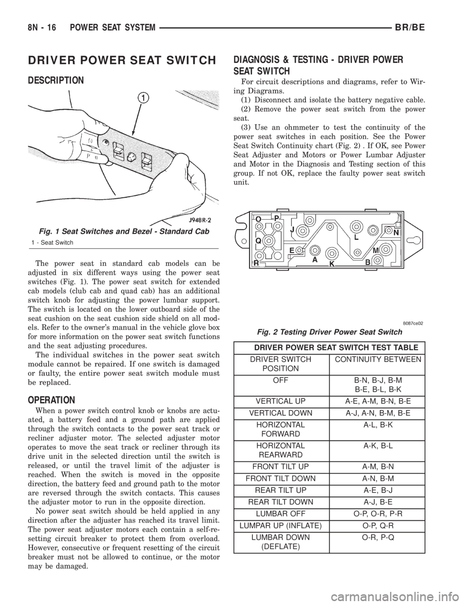
The power seat in standard cab models can be
adjusted in six different ways using the power seat
switches (Fig. 1). The power seat switch for extended
cab models (club cab and quad cab) has an additional
switch knob for adjusting the power lumbar support.
The switch is located on the lower outboard side of the
seat cushion on the seat cushion side shield on all mod-
els. Refer to the owner's manual in the vehicle glove box
for more information on the power seat switch functions
and the seat adjusting procedures.
The individual switches in the power seat switch
module cannot be repaired. If one switch is damaged
or faulty, the entire power seat switch module must
be replaced.
OPERATION
When a power switch control knob or knobs are actu-
ated, a battery feed and a ground path are applied
through the switch contacts to the power seat track or
recliner adjuster motor. The selected adjuster motor
operates to move the seat track or recliner through its
drive unit in the selected direction until the switch is
released, or until the travel limit of the adjuster is
reached. When the switch is moved in the opposite
direction, the battery feed and ground path to the motor
are reversed through the switch contacts. This causes
the adjuster motor to run in the opposite direction.
No power seat switch should be held applied in any
direction after the adjuster has reached its travel limit.
The power seat adjuster motors each contain a self-re-
setting circuit breaker to protect them from overload.
However, consecutive or frequent resetting of the circuit
breaker must not be allowed to continue, or the motor
may be damaged.
DIAGNOSIS & TESTING - DRIVER POWER
SEAT SWITCH
For circuit descriptions and diagrams, refer to Wir-
ing Diagrams.
(1)
Disconnect and isolate the battery negative cable.
(2)Remove the power seat switch from the power
seat.
(3)Use an ohmmeter to test the continuity of the
power seat switches in each position. See the Power
Seat Switch Continuity chart (Fig. 2) . If OK, see Power
Seat Adjuster and Motors or Power Lumbar Adjuster
and Motor in the Diagnosis and Testing section of this
group. If not OK, replace the faulty power seat switch
unit.
DRIVER POWER SEAT SWITCH TEST TABLE
DRIVER SWITCH
POSITIONCONTINUITY BETWEEN
OFF B-N, B-J, B-M
B-E, B-L, B-K
VERTICAL UP A-E, A-M, B-N, B-E
VERTICAL DOWN A-J, A-N, B-M, B-E
HORIZONTAL
FORWARDA-L, B-K
HORIZONTAL
REARWARDA-K, B-L
FRONT TILT UP A-M, B-N
FRONT TILT DOWN A-N, B-M
REAR TILT UP A-E, B-J
REAR TILT DOWN A-J, B-E
LUMBAR OFF O-P, O-R, P-R
LUMPAR UP (INFLATE) O-P, Q-R
LUMBAR DOWN
(DEFLATE)O-R, P-Q
Fig. 1 Seat Switches and Bezel - Standard Cab
1 - Seat Switch
Fig. 2 Testing Driver Power Seat Switch
8N - 16 POWER SEAT SYSTEMBR/BE
Page 666 of 2889
REMOVAL
(1) Disconnect and isolate the battery negative
cable.
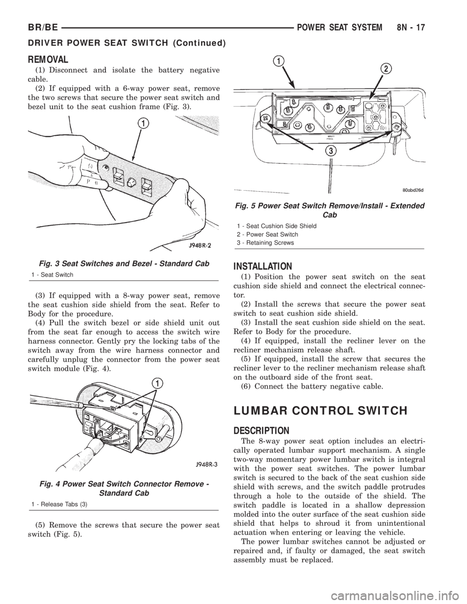
(2) If equipped with a 6-way power seat, remove
the two screws that secure the power seat switch and
bezel unit to the seat cushion frame (Fig. 3).
(3) If equipped with a 8-way power seat, remove
the seat cushion side shield from the seat. Refer to
Body for the procedure.
(4) Pull the switch bezel or side shield unit out
from the seat far enough to access the switch wire
harness connector. Gently pry the locking tabs of the
switch away from the wire harness connector and
carefully unplug the connector from the power seat
switch module (Fig. 4).
(5) Remove the screws that secure the power seat
switch (Fig. 5).
INSTALLATION
(1) Position the power seat switch on the seat
cushion side shield and connect the electrical connec-
tor.
(2) Install the screws that secure the power seat
switch to seat cushion side shield.
(3) Install the seat cushion side shield on the seat.
Refer to Body for the procedure.
(4) If equipped, install the recliner lever on the
recliner mechanism release shaft.
(5) If equipped, install the screw that secures the
recliner lever to the recliner mechanism release shaft
on the outboard side of the front seat.
(6) Connect the battery negative cable.
LUMBAR CONTROL SWITCH
DESCRIPTION
The 8-way power seat option includes an electri-
cally operated lumbar support mechanism. A single
two-way momentary power lumbar switch is integral
with the power seat switches. The power lumbar
switch is secured to the back of the seat cushion side
shield with screws, and the switch paddle protrudes
through a hole to the outside of the shield. The
switch paddle is located in a shallow depression
molded into the outer surface of the seat cushion side
shield that helps to shroud it from unintentional
actuation when entering or leaving the vehicle.
The power lumbar switches cannot be adjusted or
repaired and, if faulty or damaged, the seat switch
assembly must be replaced.
Fig. 3 Seat Switches and Bezel - Standard Cab
1 - Seat Switch
Fig. 4 Power Seat Switch Connector Remove -
Standard Cab
1 - Release Tabs (3)
Fig. 5 Power Seat Switch Remove/Install - Extended
Cab
1 - Seat Cushion Side Shield
2 - Power Seat Switch
3 - Retaining Screws
BR/BEPOWER SEAT SYSTEM 8N - 17
DRIVER POWER SEAT SWITCH (Continued)
Page 667 of 2889
OPERATION
When the power lumbar switch paddle is actuated,
a battery feed and a ground path are applied through
the switch contacts to the power lumbar adjuster
motor. The motor operates to move the lumbar
adjuster through its drive unit in the selected direc-
tion until the switch is released, or until the travel
limit of the adjuster is reached. When the switch is
moved in the opposite direction, the battery feed and
ground path to the motor are reversed through the
switch contacts. This causes the motor to run in the
opposite direction.
The power lumbar switch should not be held
applied in either direction after the adjuster has
reached its travel limit. The power lumbar adjuster
motor contains a self-resetting circuit breaker to pro-
tect it from overload. However, consecutive or fre-
quent resetting of the circuit breaker must not be
allowed to continue, or the motor may be damaged.
REMOVAL
The power lumbar switch is integral with the other
power seat switches. Refer to the appropriate driver
or passenger power front seat switch removal and/or
installation procedure.
LUMBAR MOTOR
DESCRIPTION
The 8-way power seat option includes an electri-
cally operated lumbar support mechanism. The only
visible evidence of this option is the separate power
lumbar switch control paddle that is located on the
outboard seat cushion side shield, next to the other
power seat switch control knobs. The power lumbar
adjuster and motor are concealed beneath the seat
back trim cover and padding, where they are secured
to a molded plastic back panel and to the seat back
frame.
The power lumbar adjuster cannot be repaired, and
is serviced only as a unit with the seat back frame. If
the power lumbar adjuster or the seat back frame
are damaged or faulty, the entire seat back frame
unit must be replaced. Refer toBucket Seat Back
in Body for the seat back frame service procedures.
OPERATION
The power lumbar adjuster mechanism includes a
reversible electric motor that is secured to the
inboard side of the seat back panel and is connected
to a worm-drive gearbox. The motor and gearbox
operate the lumbar adjuster mechanism in the center
of the seat back by extending and retracting a cable
that actuates a lever. The action of this lever com-
presses or relaxes a grid of flexible slats. The morethis grid is compressed, the more the slats bow out-
ward against the center of the seat back padding,
providing additional lumbar support.
DIAGNOSIS & TESTING - POWER LUMBAR
ADJUSTER
Actuate the power lumbar switch to move the
power lumbar adjuster in each direction. The power
lumbar adjuster should move in both directions. It
should be noted that the power lumber adjuster nor-
mally operates very quietly and exhibits little visible
movement. If the power lumbar adjuster fails to oper-
ate in only one direction, move the adjuster a short
distance in the opposite direction and test again to be
certain that the adjuster is not at its travel limit. If
the power lumbar adjuster still fails to operate in
only one direction, refer toPower Lumbar Switch
in the Diagnosis and Testing section of this group. If
the power lumbar adjuster fails to operate in either
direction, perform the following tests. For complete
circuit diagrams, refer toPower Seatin Wiring Dia-
grams.
(1) Check the power seat circuit breaker in the
junction block. If OK, go to Step 2. If not OK, replace
the faulty power seat circuit breaker.
(2) Check for battery voltage at the power seat cir-
cuit breaker in the junction block. If OK, go to Step
3. If not OK, repair the open fused B(+) circuit to the
fuse in the Power Distribution Center as required.
(3) Remove the outboard seat cushion side shield
from the seat. Disconnect the seat wire harness con-
nector from the power lumbar switch connector
receptacle. Check for battery voltage at the fused
B(+) circuit cavity of the power seat wire harness
connector for the power lumbar switch. If OK, go to
Step 4. If not OK, repair the open fused B(+) circuit
to the power seat circuit breaker in the junction
block as required.
(4) Check for continuity between the ground cir-
cuit cavity of the power seat wire harness connector
for the power lumbar switch and a good ground.
There should be continuity. If OK, go to Step 5. If not
OK, repair the open ground circuit to ground as
required.
(5) Test the power lumbar switch. Refer toPower
Lumbar Switchin the Diagnosis and Testing sec-
tion of this group. If the switch tests OK, test the cir-
cuits of the power seat wire harness between the
power lumbar adjuster motor and the power lumbar
switch for shorts or opens. If the circuits check OK,
replace the faulty seat back frame assembly. If the
circuits are not OK, repair the power seat wire har-
ness as required.
8N - 18 POWER SEAT SYSTEMBR/BE
LUMBAR CONTROL SWITCH (Continued)
Page 668 of 2889
PASSENGER POWER SEAT
SWITCH
DESCRIPTION
The power seat in standard cab models can be
adjusted in six different ways using the power seat
switches (Fig. 6). The power seat switch for extended
cab models (club cab and quad cab) has an additional
switch knob for adjusting the power lumbar support.
The switch is located on the lower outboard side of
the seat cushion on the seat cushion side shield on
all models. Refer to the owner's manual in the vehi-
cle glove box for more information on the power seat
switch functions and the seat adjusting procedures.
The individual switches in the power seat switch mod-
ule cannot be repaired. If one switch is damaged or
faulty, the entire power seat switch module must be
replaced.
OPERATION
When a power switch control knob or knobs are actu-
ated, a battery feed and a ground path are applied
through the switch contacts to the power seat track or
recliner adjuster motor. The selected adjuster motor
operates to move the seat track or recliner through its
drive unit in the selected direction until the switch is
released, or until the travel limit of the adjuster is
reached. When the switch is moved in the opposite direc-
tion, the battery feed and ground path to the motor are
reversed through the switch contacts. This causes the
adjuster motor to run in the opposite direction.
No power seat switch should be held applied in any
direction after the adjuster has reached its travel
limit. The power seat adjuster motors each contain a
self-resetting circuit breaker to protect them from
overload. However, consecutive or frequent resettingof the circuit breaker must not be allowed to con-
tinue, or the motor may be damaged.
DIAGNOSIS & TESTING - PASSENGER POWER
SEAT SWITCH
For circuit descriptions and diagrams, refer to Wir-
ing Diagrams.
(1)
Disconnect and isolate the battery negative cable.
(2)Remove the power seat switch from the power
seat.
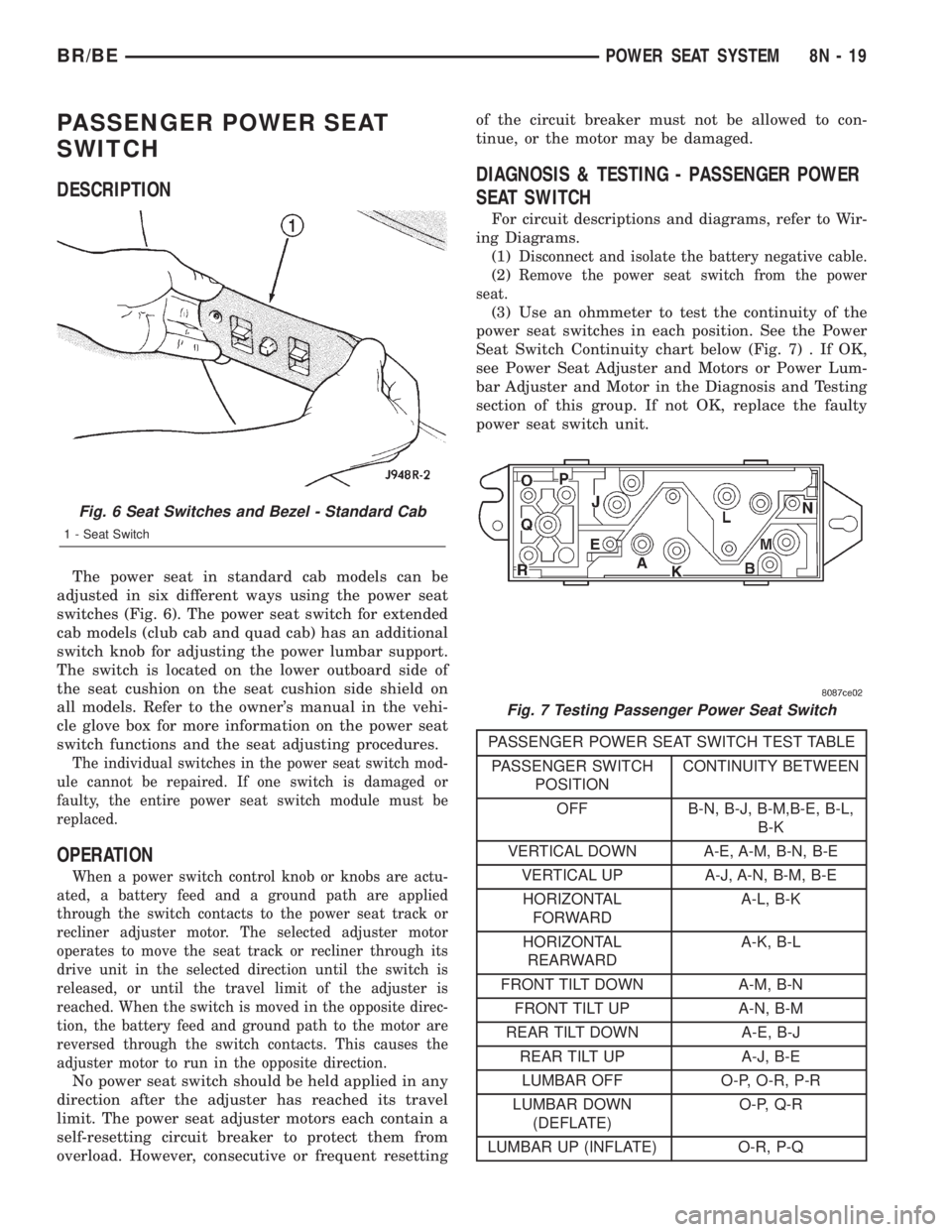
(3) Use an ohmmeter to test the continuity of the
power seat switches in each position. See the Power
Seat Switch Continuity chart below (Fig. 7) . If OK,
see Power Seat Adjuster and Motors or Power Lum-
bar Adjuster and Motor in the Diagnosis and Testing
section of this group. If not OK, replace the faulty
power seat switch unit.
PASSENGER POWER SEAT SWITCH TEST TABLE
PASSENGER SWITCH
POSITIONCONTINUITY BETWEEN
OFF B-N, B-J, B-M,B-E, B-L,
B-K
VERTICAL DOWN A-E, A-M, B-N, B-E
VERTICAL UP A-J, A-N, B-M, B-E
HORIZONTAL
FORWARDA-L, B-K
HORIZONTAL
REARWARDA-K, B-L
FRONT TILT DOWN A-M, B-N
FRONT TILT UP A-N, B-M
REAR TILT DOWN A-E, B-J
REAR TILT UP A-J, B-E
LUMBAR OFF O-P, O-R, P-R
LUMBAR DOWN
(DEFLATE)O-P, Q-R
LUMBAR UP (INFLATE) O-R, P-Q
Fig. 6 Seat Switches and Bezel - Standard Cab
1 - Seat Switch
Fig. 7 Testing Passenger Power Seat Switch
BR/BEPOWER SEAT SYSTEM 8N - 19
Page 1097 of 2889
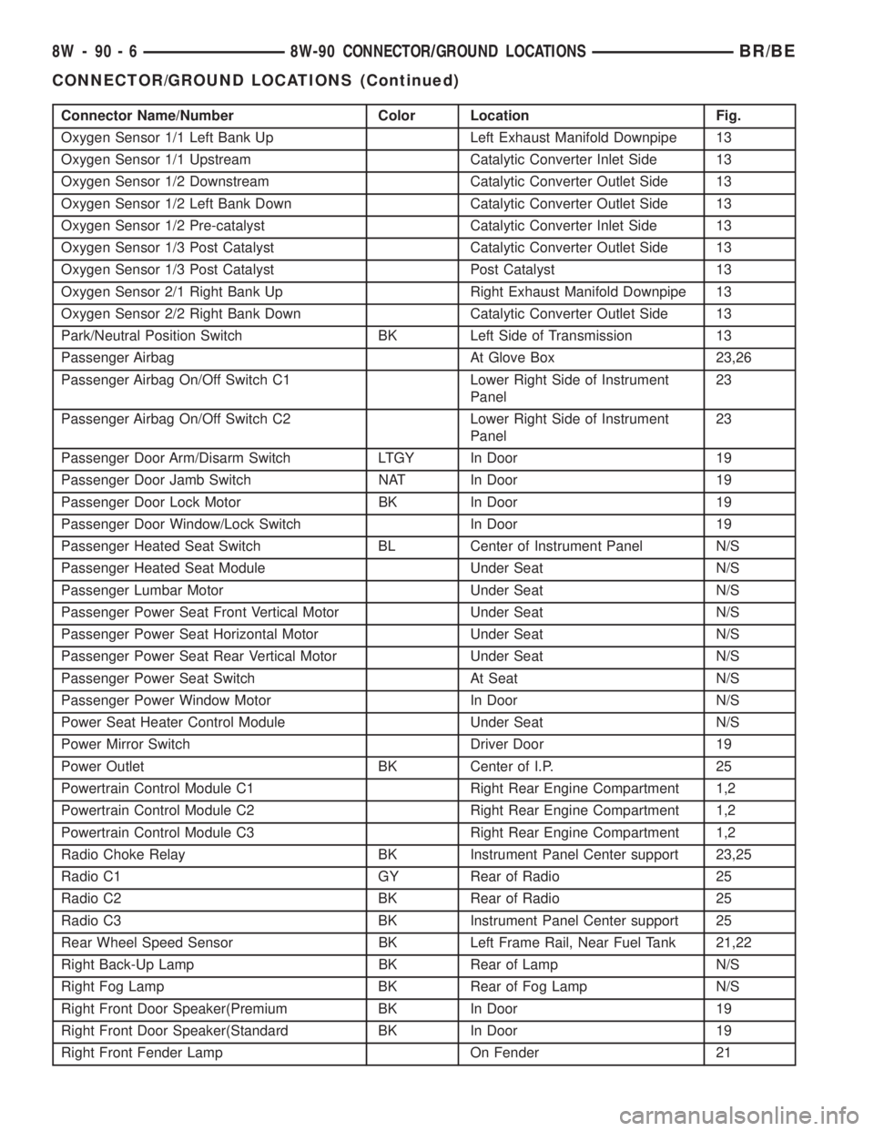
Connector Name/Number Color Location Fig.
Oxygen Sensor 1/1 Left Bank Up Left Exhaust Manifold Downpipe 13
Oxygen Sensor 1/1 Upstream Catalytic Converter Inlet Side 13
Oxygen Sensor 1/2 Downstream Catalytic Converter Outlet Side 13
Oxygen Sensor 1/2 Left Bank Down Catalytic Converter Outlet Side 13
Oxygen Sensor 1/2 Pre-catalyst Catalytic Converter Inlet Side 13
Oxygen Sensor 1/3 Post Catalyst Catalytic Converter Outlet Side 13
Oxygen Sensor 1/3 Post Catalyst Post Catalyst 13
Oxygen Sensor 2/1 Right Bank Up Right Exhaust Manifold Downpipe 13
Oxygen Sensor 2/2 Right Bank Down Catalytic Converter Outlet Side 13
Park/Neutral Position Switch BK Left Side of Transmission 13
Passenger Airbag At Glove Box 23,26
Passenger Airbag On/Off Switch C1 Lower Right Side of Instrument
Panel23
Passenger Airbag On/Off Switch C2 Lower Right Side of Instrument
Panel23
Passenger Door Arm/Disarm Switch LTGY In Door 19
Passenger Door Jamb Switch NAT In Door 19
Passenger Door Lock Motor BK In Door 19
Passenger Door Window/Lock Switch In Door 19
Passenger Heated Seat Switch BL Center of Instrument Panel N/S
Passenger Heated Seat Module Under Seat N/S
Passenger Lumbar Motor Under Seat N/S
Passenger Power Seat Front Vertical Motor Under Seat N/S
Passenger Power Seat Horizontal Motor Under Seat N/S
Passenger Power Seat Rear Vertical Motor Under Seat N/S
Passenger Power Seat Switch At Seat N/S
Passenger Power Window Motor In Door N/S
Power Seat Heater Control Module Under Seat N/S
Power Mirror Switch Driver Door 19
Power Outlet BK Center of I.P. 25
Powertrain Control Module C1 Right Rear Engine Compartment 1,2
Powertrain Control Module C2 Right Rear Engine Compartment 1,2
Powertrain Control Module C3 Right Rear Engine Compartment 1,2
Radio Choke Relay BK Instrument Panel Center support 23,25
Radio C1 GY Rear of Radio 25
Radio C2 BK Rear of Radio 25
Radio C3 BK Instrument Panel Center support 25
Rear Wheel Speed Sensor BK Left Frame Rail, Near Fuel Tank 21,22
Right Back-Up Lamp BK Rear of Lamp N/S
Right Fog Lamp BK Rear of Fog Lamp N/S
Right Front Door Speaker(Premium BK In Door 19
Right Front Door Speaker(Standard BK In Door 19
Right Front Fender Lamp On Fender 21
8W - 90 - 6 8W-90 CONNECTOR/GROUND LOCATIONSBR/BE
CONNECTOR/GROUND LOCATIONS (Continued)
Page 2704 of 2889
SEATS
TABLE OF CONTENTS
page page
SEATS
DESCRIPTION..........................131
OPERATION............................131
CENTER CONSOLE LID
REMOVAL.............................131
INSTALLATION..........................132
CENTER SEAT ARMREST/CONSOLE
REMOVAL.............................132
INSTALLATION..........................132
CENTER SEAT ARMREST/LATCH COVER
REMOVAL.............................132
INSTALLATION..........................132
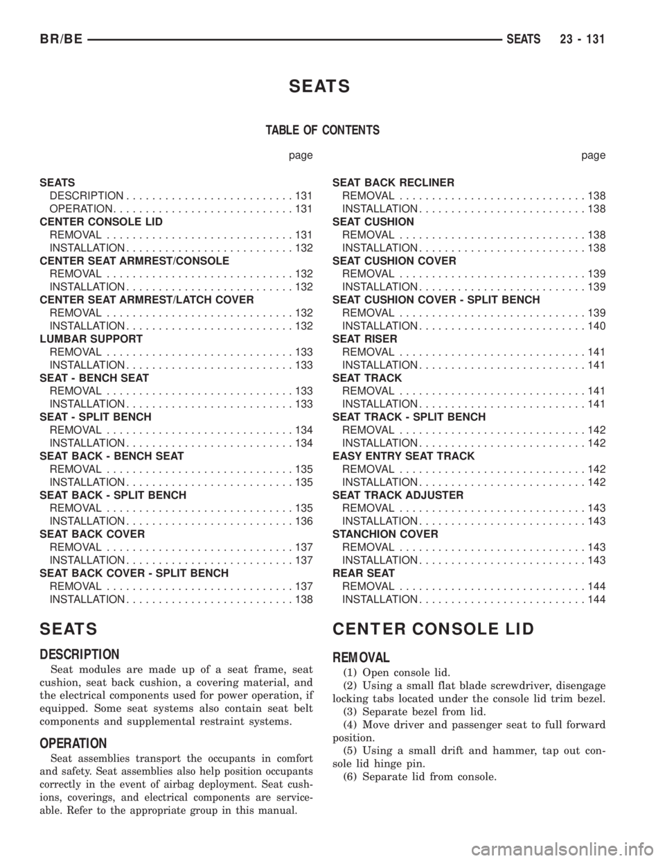
LUMBAR SUPPORT
REMOVAL.............................133
INSTALLATION..........................133
SEAT - BENCH SEAT
REMOVAL.............................133
INSTALLATION..........................133
SEAT - SPLIT BENCH
REMOVAL.............................134
INSTALLATION..........................134
SEAT BACK - BENCH SEAT
REMOVAL.............................135
INSTALLATION..........................135
SEAT BACK - SPLIT BENCH
REMOVAL.............................135
INSTALLATION..........................136
SEAT BACK COVER
REMOVAL.............................137
INSTALLATION..........................137
SEAT BACK COVER - SPLIT BENCH
REMOVAL.............................137
INSTALLATION..........................138SEAT BACK RECLINER
REMOVAL.............................138
INSTALLATION..........................138
SEAT CUSHION
REMOVAL.............................138
INSTALLATION..........................138
SEAT CUSHION COVER
REMOVAL.............................139
INSTALLATION..........................139
SEAT CUSHION COVER - SPLIT BENCH
REMOVAL.............................139
INSTALLATION..........................140
SEAT RISER
REMOVAL.............................141
INSTALLATION..........................141
SEAT TRACK
REMOVAL.............................141
INSTALLATION..........................141
SEAT TRACK - SPLIT BENCH
REMOVAL.............................142
INSTALLATION..........................142
EASY ENTRY SEAT TRACK
REMOVAL.............................142
INSTALLATION..........................142
SEAT TRACK ADJUSTER
REMOVAL.............................143
INSTALLATION..........................143
STANCHION COVER
REMOVAL.............................143
INSTALLATION..........................143
REAR SEAT
REMOVAL.............................144
INSTALLATION..........................144
SEATS
DESCRIPTION
Seat modules are made up of a seat frame, seat
cushion, seat back cushion, a covering material, and
the electrical components used for power operation, if
equipped. Some seat systems also contain seat belt
components and supplemental restraint systems.
OPERATION
Seat assemblies transport the occupants in comfort
and safety. Seat assemblies also help position occupants
correctly in the event of airbag deployment. Seat cush-
ions, coverings, and electrical components are service-
able. Refer to the appropriate group in this manual.
CENTER CONSOLE LID
REMOVAL
(1) Open console lid.
(2) Using a small flat blade screwdriver, disengage
locking tabs located under the console lid trim bezel.
(3) Separate bezel from lid.
(4) Move driver and passenger seat to full forward
position.
(5) Using a small drift and hammer, tap out con-
sole lid hinge pin.
(6) Separate lid from console.
BR/BESEATS 23 - 131
Page 2706 of 2889
LUMBAR SUPPORT
REMOVAL
(1) Remove the seat back cover. (Refer to 23 -
BODY/SEATS/SEAT BACK COVER - REMOVAL).
(2) Disengage the heated seat connectors.
(3) Partially separate the seat back foam to access
the lumbar frame clips.
(4) Separate the lumbar assembly from the seat
frame.
INSTALLATION
(1) Position the lumbar assembly on the seat back
frame.
(2) Engage the retaining clips on the seat frame.
(3) Route the lumbar wire harness through seat
assembly.
(4) Engage the heated seat wire connectors.
(5) Install the seat back cover. (Refer to 23 -
BODY/SEATS/SEAT BACK COVER - INSTALLA-
TION).
(6) Perform a function check on the seat opera-
tions.
SEAT - BENCH SEAT
REMOVAL
(1) Move seat track to forward position.
(2) Hinge seat backs forward.
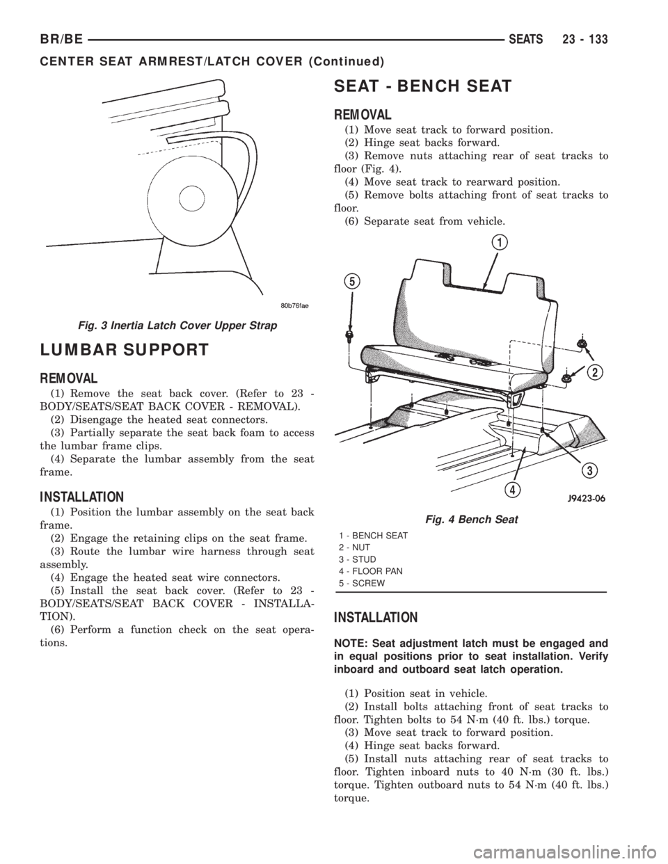
(3) Remove nuts attaching rear of seat tracks to
floor (Fig. 4).
(4) Move seat track to rearward position.
(5) Remove bolts attaching front of seat tracks to
floor.
(6) Separate seat from vehicle.
INSTALLATION
NOTE: Seat adjustment latch must be engaged and
in equal positions prior to seat installation. Verify
inboard and outboard seat latch operation.
(1) Position seat in vehicle.
(2) Install bolts attaching front of seat tracks to
floor. Tighten bolts to 54 N´m (40 ft. lbs.) torque.
(3) Move seat track to forward position.
(4) Hinge seat backs forward.
(5) Install nuts attaching rear of seat tracks to
floor. Tighten inboard nuts to 40 N´m (30 ft. lbs.)
torque. Tighten outboard nuts to 54 N´m (40 ft. lbs.)
torque.
Fig. 3 Inertia Latch Cover Upper Strap
Fig. 4 Bench Seat
1 - BENCH SEAT
2 - NUT
3 - STUD
4 - FLOOR PAN
5 - SCREW
BR/BESEATS 23 - 133
CENTER SEAT ARMREST/LATCH COVER (Continued)