2001 DODGE RAM remove seats
[x] Cancel search: remove seatsPage 54 of 2889
(5) Install the steering knuckle on the lower ball
joint. Install the lower ball joint nut and tighten to:
²LD: 129 N´m (95 ft. lbs.)
²HD: 136 N´m (110 ft. lbs.)
(5) Install the lower ball joint cotter pin.
(6) Install the stabilizer bar link on the lower sus-
pension arm. Install the grommet, retainer and nut
and tighten to 37 N´m (27 ft. lbs.).
(7) Install the tie rod end on the steering knuckle
and tighten nut to 108 N´m (80 ft. lbs.). Install cotter
pin.
(8) Install the brake rotor and caliper assembly,
(Refer to 5 - BRAKES/HYDRAULIC/MECHANICAL/
ROTORS - INSTALLATION).
(9) Install the tire and wheel assembly, (Refer to
22 - TIRES/WHEELS/WHEELS - STANDARD PRO-
CEDURE).
(10) Remove the support and lower the vehicle.
(11) Tighten the suspension arm crossmember
nuts to 169 N´m (125 ft. lbs.).
SHOCK
DESCRIPTION
The top of the shocks mounts on frame brackets
using grommets. The bottom of the shock is bolted to
the lower suspension arms.
OPERATION
The shock absorbers dampen jounce and rebound
of the vehicle over various road conditions.
DIAGNOSIS AND TESTING - SHOCK
A knocking or rattling noise from a shock absorber
may be caused by movement between mounting
bushings and metal brackets or attaching compo-
nents. These noises can usually be stopped by tight-
ening the attaching nuts. If the noise persists,
inspect for damaged and worn bushings, and attach-
ing components. Repair as necessary if any of these
conditions exist.
A squeaking noise from the shock absorber may be
caused by the hydraulic valving and may be intermit-
tent. This condition is not repairable and the shock
absorber must be replaced.
The shock absorbers are not refillable or adjust-
able. If a malfunction occurs, the shock absorber
must be replaced. To test a shock absorber, hold it in
an upright position and force the piston in and out of
the cylinder four or five times. The action throughout
each stroke should be smooth and even.
The shock absorber bushings do not require any
type of lubrication. Do not attempt to stop bushing
noise by lubricating them. Grease and mineral oil-
base lubricants will deteriorate the bushing.
REMOVAL
(1) Raise and support vehicle.
(2) Remove shock upper nut and remove retainer
and grommet.
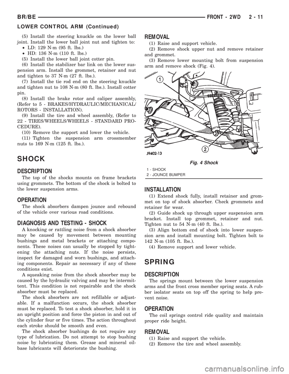
(3) Remove lower mounting bolt from suspension
arm and remove shock (Fig. 4).
INSTALLATION
(1) Extend shock fully, install retainer and grom-
met on top of shock absorber. Check grommets and
retainer for wear.
(2) Guide shock up through upper suspension arm
bracket. Install top grommet, retainer and nut.
Tighten nut to 54 N´m (40 ft. lbs.).
(3) Align bottom end of shock into lower suspen-
sion arm and install mounting bolt. Tighten bolt to
142 N´m (105 ft. lbs.).
(4) Remove support and lower vehicle.
SPRING
DESCRIPTION
The springs mount between the lower suspension
arms and the front cross member spring seats. A rub-
ber isolator seats on top off the spring to help pre-
vent noise.
OPERATION
The coil springs control ride quality and maintain
proper ride height.
REMOVAL
(1) Raise and support the vehicle.
(2) Remove the tire and wheel assembly.
Fig. 4 Shock
1 - SHOCK
2 - JOUNCE BUMPER
BR/BEFRONT - 2WD 2 - 11
LOWER CONTROL ARM (Continued)
Page 65 of 2889
(4) Install upper grommet and retainer. Install
upper shock nut and tighten to 47 N´m (35 ft. lbs).
SPRING
DESCRIPTION
The springs use a rubber isolators between the
frame bracket and spring. The isolators help prevent
road noise. The bottom of the spring sits on a seat
mounted to the axle.
OPERATION
The coil springs control ride quality and maintain
proper ride height.
REMOVAL
(1) Raise and support the vehicle. Position a
hydraulic jack under the axle to support it.
(2) Paint or scribe alignment marks on lower sus-
pension arm cam adjusters and axle bracket for
installation reference.
(3) Remove the upper suspension arm and loosen
lower suspension arm bolts.
(4) Mark and disconnect the front propeller shaft
from the axle 4x4 models.
(5) Disconnect the track bar from the frame rail
bracket.
(6) Disconnect the drag link from pitman arm.
(7) Disconnect the stabilizer bar link and shock
absorber from the axle.(8) Lower the axle until the spring is free from the
upper mount. Remove the coil spring.
INSTALLATION
(1) Position the coil spring on the axle pad.
(2) Raise the axle into position until the spring
seats in the upper mount.
(3) Connect the stabilizer bar links and shock
absorbers to the axle bracket. Connect the track bar
to the frame rail bracket.
(4) Install the upper suspension arm.
(5) Install the front propeller shaft to the axle 4x4
model.
(6) Install drag link to pitman arm and tighten
nut to specifications. Install new cotter pin.
(7) Remove the supports and lower the vehicle.
(8) Tighten the following suspension components
to specifications:
²Link to stabilizer bar nut.
²Lower shock bolt.
²Track bar bolt at axle shaft tube bracket.
²Upper suspension arm nut at axle bracket.
²Upper suspension nut at frame bracket.
²Align lower suspension arm reference marks and
tighten cam nut.
²Lower suspension nut at frame bracket.
STABILIZER BAR
DESCRIPTION
The stabilizer bar extends across the front under-
side of the chassis and connects to the frame rails.
Links are connected from the bar to the axle brack-
ets. Stabilizer bar mounts are isolated by teflon lined
rubber bushings.
OPERATION
The stabilizer bar is used to minimize vehicle front
sway during turns. The spring steel bar helps to con-
trol the vehicle body in relationship to the suspen-
sion.
REMOVAL
(1) Raise and support the vehicle.
(2) Hold the stabilizer link shafts with a wrench
and remove the link nuts at the stabilizer bar.
(3) Remove the retainers and grommets from the
stabilizer bar links.
(4) Remove the stabilizer bar link nuts from the
axle brackets.
(5) Remove the links from the axle brackets with
Puller C-3894-A (Fig. 18).
(6) Remove the stabilizer bar clamps from the
frame rails and remove the stabilizer bar.
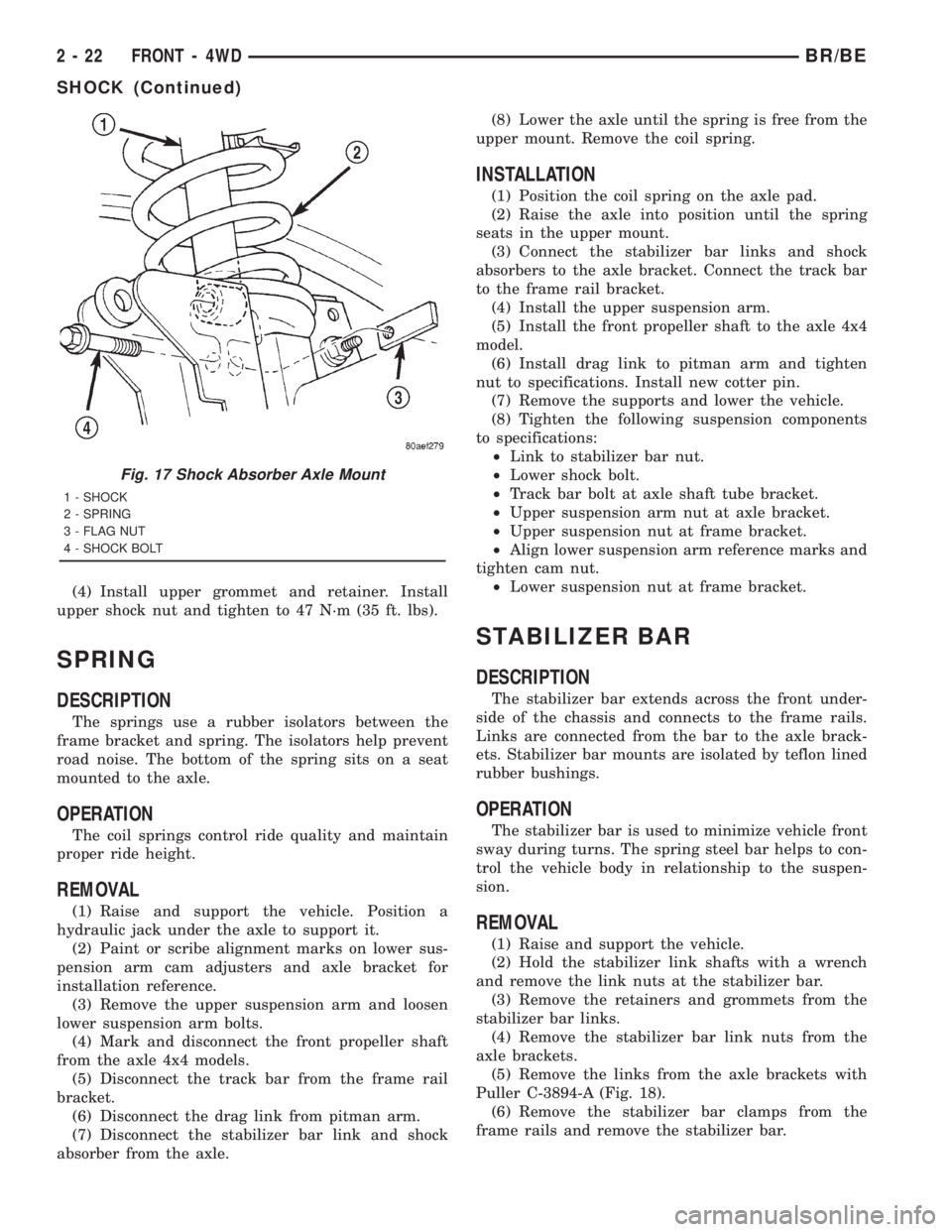
Fig. 17 Shock Absorber Axle Mount
1 - SHOCK
2 - SPRING
3 - FLAG NUT
4 - SHOCK BOLT
2 - 22 FRONT - 4WDBR/BE
SHOCK (Continued)
Page 693 of 2889
INSTALLATION
The following procedure is for replacement of a
faulty or damaged driver airbag. If the driver airbag
has been deployed, the clockspring and the steering
column assembly must also be replaced. (Refer to 8 -
ELECTRICAL/RESTRAINTS/CLOCKSPRING -
REMOVAL) and (Refer to 19 - STEERING/COLUMN
- REMOVAL).
WARNING: DISABLE THE AIRBAG SYSTEM
BEFORE ATTEMPTING ANY STEERING WHEEL,
STEERING COLUMN, OR INSTRUMENT PANEL
COMPONENT DIAGNOSIS OR SERVICE. DISCON-
NECT AND ISOLATE THE BATTERY NEGATIVE
(GROUND) CABLE, THEN WAIT TWO MINUTES FOR
THE AIRBAG SYSTEM CAPACITOR TO DISCHARGE
BEFORE PERFORMING FURTHER DIAGNOSIS OR
SERVICE. THIS IS THE ONLY SURE WAY TO DIS-
ABLE THE AIRBAG SYSTEM. FAILURE TO TAKE
THE PROPER PRECAUTIONS COULD RESULT IN
ACCIDENTAL AIRBAG DEPLOYMENT AND POSSI-
BLE PERSONAL INJURY.
WARNING: USE EXTREME CARE TO PREVENT ANY
FOREIGN MATERIAL FROM ENTERING THE DRIVER
AIRBAG, OR BECOMING ENTRAPPED BETWEEN
THE DRIVER AIRBAG CUSHION AND THE DRIVER
AIRBAG TRIM COVER. FAILURE TO OBSERVE THIS
WARNING COULD RESULT IN OCCUPANT INJURIES
UPON AIRBAG DEPLOYMENT.
WARNING: THE DRIVER AIRBAG TRIM COVER
MUST NEVER BE PAINTED. REPLACEMENT TRIM
COVERS ARE SERVICED IN THE ORIGINAL COL-
ORS. PAINT MAY CHANGE THE WAY IN WHICH THE
MATERIAL OF THE TRIM COVER RESPONDS TO AN
AIRBAG DEPLOYMENT. FAILURE TO OBSERVE
THIS WARNING COULD RESULT IN OCCUPANT
INJURIES UPON AIRBAG DEPLOYMENT.
(1) Assemble the driver airbag trim cover onto the
airbag housing. (Refer to 8 - ELECTRICAL/RE-
STRAINTS/DRIVER AIRBAG - ASSEMBLY).
(2) When installing the driver airbag, reconnect
the clockspring driver airbag pigtail wire harness
connector to the airbag inflator connector receptacle
by pressing straight in on the connector (Fig. 10). You
can be certain that the connector is fully engaged by
listening carefully for a distinct, audible click as the
connector snaps into place.
(3) Reconnect the clockspring horn switch pigtail
wire harness connector to the horn switch feed pig-
tail wire connector, which is located on the back of
the driver airbag.(4) Carefully position the driver airbag in the
steering wheel. Be certain that the clockspring pig-
tail wires in the steering wheel hub area are not
pinched between the driver airbag and the steering
wheel.
(5) From the underside of the steering wheel,
install and tighten the two screws that secure the
driver airbag to the steering wheel armature.
Tighten the screws to 10.2 N´m (90 in. lbs.).
(6) Do not reconnect the battery negative cable at
this time. The airbag system verification test proce-
dure should be performed following service of any
airbag system component. (Refer to 8 - ELECTRI-
CAL/RESTRAINTS - STANDARD PROCEDURE -
VERIFICATION TEST).
FRONT SEAT BELT &
RETRACTOR
REMOVAL - STANDARD CAB
WARNING: DURING AND FOLLOWING ANY SEAT
BELT SERVICE, CAREFULLY INSPECT ALL SEAT
BELTS, BUCKLES, MOUNTING HARDWARE, AND
RETRACTORS FOR PROPER INSTALLATION,
OPERATION, OR DAMAGE. REPLACE ANY BELT
THAT IS CUT, FRAYED, OR TORN. STRAIGHTEN
ANY BELT THAT IS TWISTED. TIGHTEN ANY
LOOSE FASTENERS. REPLACE ANY BELT THAT
HAS A DAMAGED OR INOPERATIVE BUCKLE OR
RETRACTOR. REPLACE ANY BELT THAT HAS A
BENT OR DAMAGED LATCH PLATE OR ANCHOR
PLATE. NEVER ATTEMPT TO REPAIR A SEAT BELT
COMPONENT. ALWAYS REPLACE DAMAGED OR
FAULTY SEAT BELT COMPONENTS WITH THE COR-
RECT, NEW AND UNUSED REPLACEMENT PARTS
LISTED IN THE MOPAR PARTS CATALOG.
(1) Move the front seats to their most forward
position for easiest access to the front shoulder belt
lower seat belt anchor plate, the retractor, and the
B-pillar.
(2) Remove the screw that secures the lower seat
belt anchor plate to the floor panel near the base of
the B-pillar.
(3) Unsnap and lift the front shoulder belt turning
loop cover to access the screw that secures the turn-
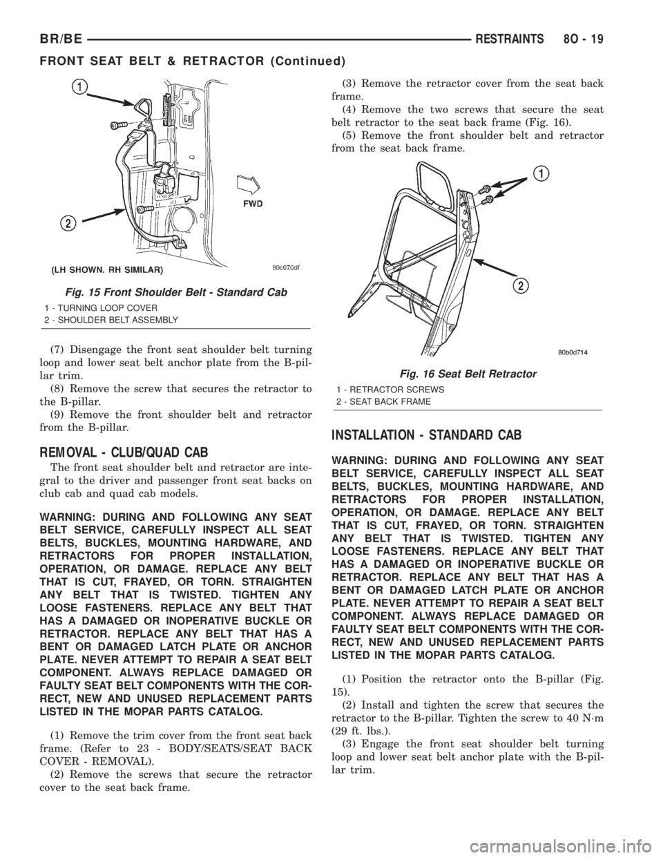
ing loop to the height adjuster (Fig. 15).
(4) Remove the screw that secures the shoulder
belt turning loop to the height adjuster.
(5) Remove the shoulder belt turning loop from the
height adjuster.
(6) Remove the trim from the B-pillar. (Refer to 23
- BODY/INTERIOR/B-PILLAR TRIM - REMOVAL).
8O - 18 RESTRAINTSBR/BE
DRIVER AIRBAG (Continued)
Page 694 of 2889
(7) Disengage the front seat shoulder belt turning
loop and lower seat belt anchor plate from the B-pil-
lar trim.
(8) Remove the screw that secures the retractor to
the B-pillar.
(9) Remove the front shoulder belt and retractor
from the B-pillar.
REMOVAL - CLUB/QUAD CAB
The front seat shoulder belt and retractor are inte-
gral to the driver and passenger front seat backs on
club cab and quad cab models.
WARNING: DURING AND FOLLOWING ANY SEAT
BELT SERVICE, CAREFULLY INSPECT ALL SEAT
BELTS, BUCKLES, MOUNTING HARDWARE, AND
RETRACTORS FOR PROPER INSTALLATION,
OPERATION, OR DAMAGE. REPLACE ANY BELT
THAT IS CUT, FRAYED, OR TORN. STRAIGHTEN
ANY BELT THAT IS TWISTED. TIGHTEN ANY
LOOSE FASTENERS. REPLACE ANY BELT THAT
HAS A DAMAGED OR INOPERATIVE BUCKLE OR
RETRACTOR. REPLACE ANY BELT THAT HAS A
BENT OR DAMAGED LATCH PLATE OR ANCHOR
PLATE. NEVER ATTEMPT TO REPAIR A SEAT BELT
COMPONENT. ALWAYS REPLACE DAMAGED OR
FAULTY SEAT BELT COMPONENTS WITH THE COR-
RECT, NEW AND UNUSED REPLACEMENT PARTS
LISTED IN THE MOPAR PARTS CATALOG.
(1) Remove the trim cover from the front seat back
frame. (Refer to 23 - BODY/SEATS/SEAT BACK
COVER - REMOVAL).
(2) Remove the screws that secure the retractor
cover to the seat back frame.(3) Remove the retractor cover from the seat back
frame.
(4) Remove the two screws that secure the seat
belt retractor to the seat back frame (Fig. 16).
(5) Remove the front shoulder belt and retractor
from the seat back frame.
INSTALLATION - STANDARD CAB
WARNING: DURING AND FOLLOWING ANY SEAT
BELT SERVICE, CAREFULLY INSPECT ALL SEAT
BELTS, BUCKLES, MOUNTING HARDWARE, AND
RETRACTORS FOR PROPER INSTALLATION,
OPERATION, OR DAMAGE. REPLACE ANY BELT
THAT IS CUT, FRAYED, OR TORN. STRAIGHTEN
ANY BELT THAT IS TWISTED. TIGHTEN ANY
LOOSE FASTENERS. REPLACE ANY BELT THAT
HAS A DAMAGED OR INOPERATIVE BUCKLE OR
RETRACTOR. REPLACE ANY BELT THAT HAS A
BENT OR DAMAGED LATCH PLATE OR ANCHOR
PLATE. NEVER ATTEMPT TO REPAIR A SEAT BELT
COMPONENT. ALWAYS REPLACE DAMAGED OR
FAULTY SEAT BELT COMPONENTS WITH THE COR-
RECT, NEW AND UNUSED REPLACEMENT PARTS
LISTED IN THE MOPAR PARTS CATALOG.
(1) Position the retractor onto the B-pillar (Fig.
15).
(2) Install and tighten the screw that secures the
retractor to the B-pillar. Tighten the screw to 40 N´m
(29 ft. lbs.).
(3) Engage the front seat shoulder belt turning
loop and lower seat belt anchor plate with the B-pil-
lar trim.
Fig. 15 Front Shoulder Belt - Standard Cab
1 - TURNING LOOP COVER
2 - SHOULDER BELT ASSEMBLY
Fig. 16 Seat Belt Retractor
1 - RETRACTOR SCREWS
2 - SEAT BACK FRAME
BR/BERESTRAINTS 8O - 19
FRONT SEAT BELT & RETRACTOR (Continued)
Page 695 of 2889
(4) Reinstall the trim onto the B-pillar. (Refer to
23 - BODY/INTERIOR/B-PILLAR TRIM - INSTAL-
LATION).
(5) Position the shoulder belt turning loop onto the
height adjuster.
(6) Install and tighten the screw that secures the
shoulder belt turning loop to the height adjuster.
Tighten the screw to 30 N´m (22 ft. lbs.).
(7) Fold and snap the cover over the front shoulder
belt turning loop to conceal the screw that secures
the turning loop to the height adjuster.
(8) Install and tighten the screw that secures the
lower seat belt anchor plate to the floor panel near
the base of the B-pillar. Tighten the screw to 40 N´m
(29 ft. lbs.).
INSTALLATION - CLUB/QUAD CAB
The front seat shoulder belt and retractor are inte-
gral to the driver and passenger front seat backs on
club cab and quad cab models.
WARNING: DURING AND FOLLOWING ANY SEAT
BELT SERVICE, CAREFULLY INSPECT ALL SEAT
BELTS, BUCKLES, MOUNTING HARDWARE, AND
RETRACTORS FOR PROPER INSTALLATION,
OPERATION, OR DAMAGE. REPLACE ANY BELT
THAT IS CUT, FRAYED, OR TORN. STRAIGHTEN
ANY BELT THAT IS TWISTED. TIGHTEN ANY
LOOSE FASTENERS. REPLACE ANY BELT THAT
HAS A DAMAGED OR INOPERATIVE BUCKLE OR
RETRACTOR. REPLACE ANY BELT THAT HAS A
BENT OR DAMAGED LATCH PLATE OR ANCHOR
PLATE. NEVER ATTEMPT TO REPAIR A SEAT BELT
COMPONENT. ALWAYS REPLACE DAMAGED OR
FAULTY SEAT BELT COMPONENTS WITH THE COR-
RECT, NEW AND UNUSED REPLACEMENT PARTS
LISTED IN THE MOPAR PARTS CATALOG.
(1) Position the front shoulder belt and retractor
onto the seat back frame.
(2) Install and tighten the two screws that secure
the seat belt retractor to the seat back frame (Fig.
16). Tighten the screws to 16 N´m (12 ft. lbs.).
(3) Position the retractor cover onto the seat back
frame.
(4) Install and tighten the screws that secure the
retractor cover to the seat back frame. Tighten the
screws to 2 N´m (17 in. lbs.).
(5) Reinstall the trim cover onto the front seat
back frame. (Refer to 23 - BODY/SEATS/SEAT BACK
COVER - INSTALLATION).
FRONT SEAT BELT BUCKLE
REMOVAL
WARNING: DURING AND FOLLOWING ANY SEAT
BELT SERVICE, CAREFULLY INSPECT ALL SEAT
BELTS, BUCKLES, MOUNTING HARDWARE, AND
RETRACTORS FOR PROPER INSTALLATION,
OPERATION, OR DAMAGE. REPLACE ANY BELT
THAT IS CUT, FRAYED, OR TORN. STRAIGHTEN
ANY BELT THAT IS TWISTED. TIGHTEN ANY
LOOSE FASTENERS. REPLACE ANY BELT THAT
HAS A DAMAGED OR INOPERATIVE BUCKLE OR
RETRACTOR. REPLACE ANY BELT THAT HAS A
BENT OR DAMAGED LATCH PLATE OR ANCHOR
PLATE. NEVER ATTEMPT TO REPAIR A SEAT BELT
COMPONENT. ALWAYS REPLACE DAMAGED OR
FAULTY SEAT BELT COMPONENTS WITH THE COR-
RECT, NEW AND UNUSED REPLACEMENT PARTS
LISTED IN THE MOPAR PARTS CATALOG.
(1) Move the front seat to its most forward position
for easiest access to the front seat belt buckle
anchors.
(2) Tilt both front seat backs forward far enough to
access the seat belt buckle anchor screws.
(3) On the driver's side only, disconnect the body
wire harness connector for the seat belt switch from
the seat belt switch pigtail wire connector on the seat
belt buckle.
(4) Remove the screw that secures the seat belt
buckle to the anchor on the seat cushion frame.
(5) Remove the front seat belt buckle from the seat
cushion frame.
INSTALLATION
WARNING: DURING AND FOLLOWING ANY SEAT
BELT SERVICE, CAREFULLY INSPECT ALL SEAT
BELTS, BUCKLES, MOUNTING HARDWARE, AND
RETRACTORS FOR PROPER INSTALLATION,
OPERATION, OR DAMAGE. REPLACE ANY BELT
THAT IS CUT, FRAYED, OR TORN. STRAIGHTEN
ANY BELT THAT IS TWISTED. TIGHTEN ANY
LOOSE FASTENERS. REPLACE ANY BELT THAT
HAS A DAMAGED OR INOPERATIVE BUCKLE OR
RETRACTOR. REPLACE ANY BELT THAT HAS A
BENT OR DAMAGED LATCH PLATE OR ANCHOR
PLATE. NEVER ATTEMPT TO REPAIR A SEAT BELT
COMPONENT. ALWAYS REPLACE DAMAGED OR
FAULTY SEAT BELT COMPONENTS WITH THE COR-
RECT, NEW AND UNUSED REPLACEMENT PARTS
LISTED IN THE MOPAR PARTS CATALOG.
(1) Position the front seat belt buckle onto the seat
cushion frame.
8O - 20 RESTRAINTSBR/BE
FRONT SEAT BELT & RETRACTOR (Continued)
Page 701 of 2889
(5) Position the passenger airbag on/off switch and
face plate unit to the opening in the instrument
panel (Fig. 21).
(6) Install and tighten the three screws that secure
the passenger airbag on/off switch face plate to the
instrument panel. Tighten the screws to 2.2 N´m (20
in. lbs.).
(7) Reinstall the glove box onto the instrument
panel. (Refer to 23 - BODY/INSTRUMENT PANEL/
GLOVE BOX - INSTALLATION).
(8) Reinstall the cluster bezel onto the instrument
panel. (Refer to 23 - BODY/INSTRUMENT PANEL/
CLUSTER BEZEL - INSTALLATION).
(9) Do not reconnect the battery negative cable at
this time. The airbag system verification test proce-
dure should be performed following service of any
airbag system component. (Refer to 8 - ELECTRI-
CAL/RESTRAINTS - STANDARD PROCEDURE -
VERIFICATION TEST).
REAR SEAT BELT &
RETRACTOR
REMOVAL
WARNING: DURING AND FOLLOWING ANY SEAT
BELT SERVICE, CAREFULLY INSPECT ALL SEAT
BELTS, BUCKLES, MOUNTING HARDWARE, AND
RETRACTORS FOR PROPER INSTALLATION,
OPERATION, OR DAMAGE. REPLACE ANY BELT
THAT IS CUT, FRAYED, OR TORN. STRAIGHTEN
ANY BELT THAT IS TWISTED. TIGHTEN ANY
LOOSE FASTENERS. REPLACE ANY BELT THAT
HAS A DAMAGED OR INOPERATIVE BUCKLE OR
RETRACTOR. REPLACE ANY BELT THAT HAS A
BENT OR DAMAGED LATCH PLATE OR ANCHOR
PLATE. NEVER ATTEMPT TO REPAIR A SEAT BELT
COMPONENT. ALWAYS REPLACE DAMAGED OR
FAULTY SEAT BELT COMPONENTS WITH THE COR-
RECT, NEW AND UNUSED REPLACEMENT PARTS
LISTED IN THE MOPAR PARTS CATALOG.
(1) Remove the rear seat from the passenger com-
partment. (Refer to 23 - BODY/SEATS/REAR SEAT -
REMOVAL).
(2) Remove the trim cover from the door sill.
(Refer to 23 - BODY/INTERIOR/DOOR SILL TRIM -
REMOVAL).
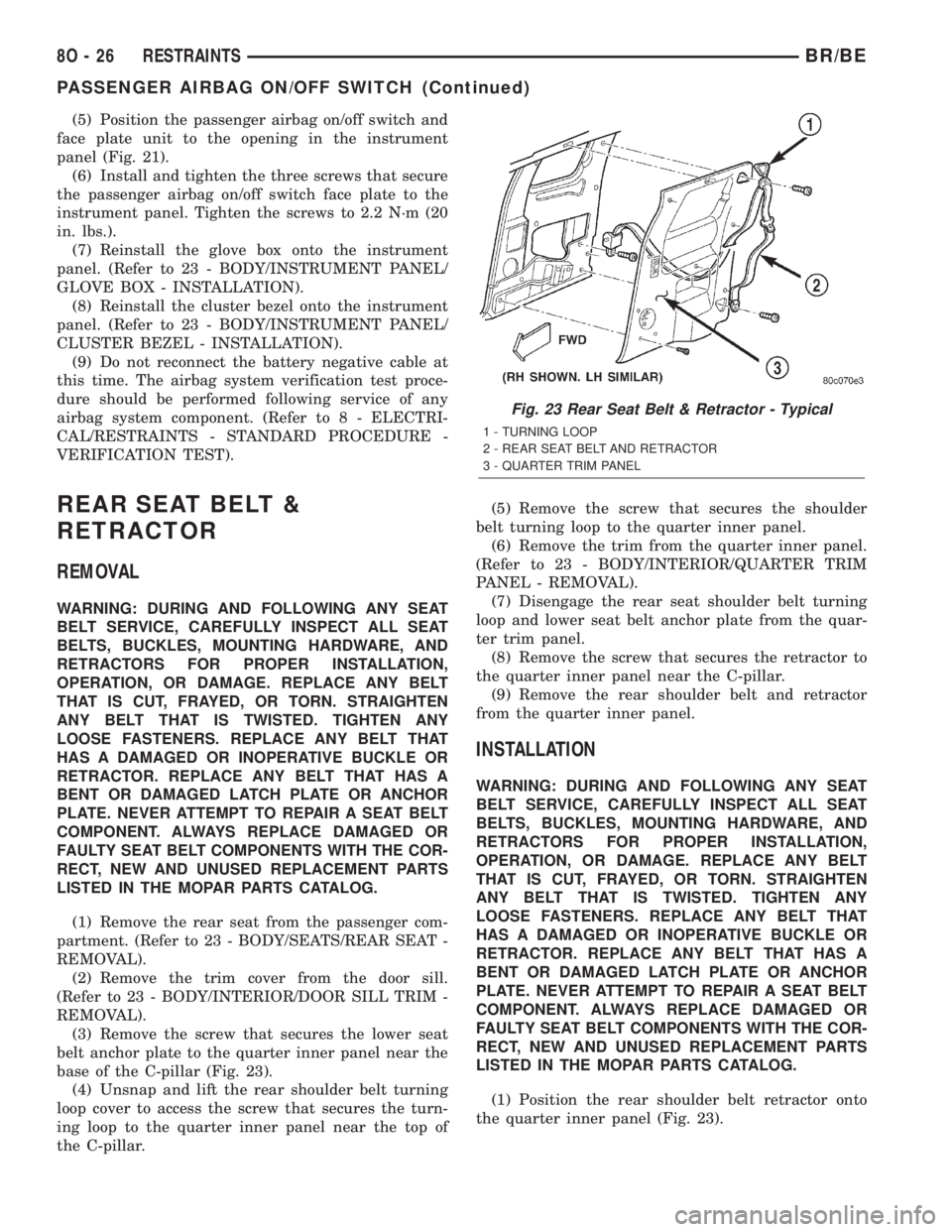
(3) Remove the screw that secures the lower seat
belt anchor plate to the quarter inner panel near the
base of the C-pillar (Fig. 23).
(4) Unsnap and lift the rear shoulder belt turning
loop cover to access the screw that secures the turn-
ing loop to the quarter inner panel near the top of
the C-pillar.(5) Remove the screw that secures the shoulder
belt turning loop to the quarter inner panel.
(6) Remove the trim from the quarter inner panel.
(Refer to 23 - BODY/INTERIOR/QUARTER TRIM
PANEL - REMOVAL).
(7) Disengage the rear seat shoulder belt turning
loop and lower seat belt anchor plate from the quar-
ter trim panel.
(8) Remove the screw that secures the retractor to
the quarter inner panel near the C-pillar.
(9) Remove the rear shoulder belt and retractor
from the quarter inner panel.
INSTALLATION
WARNING: DURING AND FOLLOWING ANY SEAT
BELT SERVICE, CAREFULLY INSPECT ALL SEAT
BELTS, BUCKLES, MOUNTING HARDWARE, AND
RETRACTORS FOR PROPER INSTALLATION,
OPERATION, OR DAMAGE. REPLACE ANY BELT
THAT IS CUT, FRAYED, OR TORN. STRAIGHTEN
ANY BELT THAT IS TWISTED. TIGHTEN ANY
LOOSE FASTENERS. REPLACE ANY BELT THAT
HAS A DAMAGED OR INOPERATIVE BUCKLE OR
RETRACTOR. REPLACE ANY BELT THAT HAS A
BENT OR DAMAGED LATCH PLATE OR ANCHOR
PLATE. NEVER ATTEMPT TO REPAIR A SEAT BELT
COMPONENT. ALWAYS REPLACE DAMAGED OR
FAULTY SEAT BELT COMPONENTS WITH THE COR-
RECT, NEW AND UNUSED REPLACEMENT PARTS
LISTED IN THE MOPAR PARTS CATALOG.
(1) Position the rear shoulder belt retractor onto
the quarter inner panel (Fig. 23).
Fig. 23 Rear Seat Belt & Retractor - Typical
1 - TURNING LOOP
2 - REAR SEAT BELT AND RETRACTOR
3 - QUARTER TRIM PANEL
8O - 26 RESTRAINTSBR/BE
PASSENGER AIRBAG ON/OFF SWITCH (Continued)
Page 702 of 2889
(2) Install and tighten the screw that secures the
retractor to the quarter inner panel. Tighten the
screw to 40 N´m (29 ft. lbs.).
(3) Engage the rear seat shoulder belt turning loop
and lower seat belt anchor plate with the quarter
trim panel.
(4) Reinstall the trim onto the quarter inner panel.
(Refer to 23 - BODY/INTERIOR/QUARTER TRIM
PANEL - INSTALLATION).
(5) Position the shoulder belt turning loop onto the
quarter inner panel near the top of the C-pillar.
(6) Install and tighten the screw that secures the
shoulder belt turning loop to the quarter inner panel.
Tighten the screw to 40 N´m (29 ft. lbs.).
(7) Fold and snap the cover over the rear shoulder
belt turning loop to conceal the screw that secures
the turning loop to the quarter inner panel.
(8) Position the lower seat belt anchor plate onto
the quarter inner panel near the base of the C-pillar.
(9) Install and tighten the screw that secures the
lower seat belt anchor plate to the quarter inner
panel near the base of the C-pillar. Tighten the screw
to 40 N´m (29 ft. lbs.).
(10) Reinstall the trim cover onto the door sill.
(Refer to 23 - BODY/INTERIOR/DOOR SILL TRIM -
INSTALLATION).
(11) Reinstall the rear seat into the passenger
compartment. (Refer to 23 - BODY/SEATS/REAR
SEAT - INSTALLATION).
REAR SEAT BELT BUCKLE
REMOVAL
WARNING: DURING AND FOLLOWING ANY SEAT
BELT SERVICE, CAREFULLY INSPECT ALL SEAT
BELTS, BUCKLES, MOUNTING HARDWARE, AND
RETRACTORS FOR PROPER INSTALLATION,
OPERATION, OR DAMAGE. REPLACE ANY BELT
THAT IS CUT, FRAYED, OR TORN. STRAIGHTEN
ANY BELT THAT IS TWISTED. TIGHTEN ANY
LOOSE FASTENERS. REPLACE ANY BELT THAT
HAS A DAMAGED OR INOPERATIVE BUCKLE OR
RETRACTOR. REPLACE ANY BELT THAT HAS A
BENT OR DAMAGED LATCH PLATE OR ANCHOR
PLATE. NEVER ATTEMPT TO REPAIR A SEAT BELT
COMPONENT. ALWAYS REPLACE DAMAGED OR
FAULTY SEAT BELT COMPONENTS WITH THE COR-
RECT, NEW AND UNUSED REPLACEMENT PARTS
LISTED IN THE MOPAR PARTS CATALOG.
(1) Disengage the rear seat latch by pulling the
release handle on the underside of the rear seat
cushion.(2) Fold the rear seat unit up and back against the
cab back panel (stowed position) for access to the
rear seat belt buckle anchors.
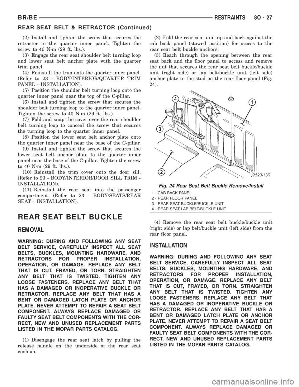
(3) Reach through the opening between the rear
seat back and the floor panel to access and remove
the nut that secures the rear seat belt buckle/buckle
unit (right side) or lap belt/buckle unit (left side)
anchor plate to the stud on the rear floor panel (Fig.
24).
(4) Remove the rear seat belt buckle/buckle unit
(right side) or lap belt/buckle unit (left side) from the
rear floor panel.INSTALLATION
WARNING: DURING AND FOLLOWING ANY SEAT
BELT SERVICE, CAREFULLY INSPECT ALL SEAT
BELTS, BUCKLES, MOUNTING HARDWARE, AND
RETRACTORS FOR PROPER INSTALLATION,
OPERATION, OR DAMAGE. REPLACE ANY BELT
THAT IS CUT, FRAYED, OR TORN. STRAIGHTEN
ANY BELT THAT IS TWISTED. TIGHTEN ANY
LOOSE FASTENERS. REPLACE ANY BELT THAT
HAS A DAMAGED OR INOPERATIVE BUCKLE OR
RETRACTOR. REPLACE ANY BELT THAT HAS A
BENT OR DAMAGED LATCH PLATE OR ANCHOR
PLATE. NEVER ATTEMPT TO REPAIR A SEAT BELT
COMPONENT. ALWAYS REPLACE DAMAGED OR
FAULTY SEAT BELT COMPONENTS WITH THE COR-
RECT, NEW AND UNUSED REPLACEMENT PARTS
LISTED IN THE MOPAR PARTS CATALOG.
Fig. 24 Rear Seat Belt Buckle Remove/Install
1 - CAB BACK PANEL
2 - REAR FLOOR PANEL
3 - REAR SEAT BUCKLE/BUCKLE UNIT
4 - REAR SEAT LAP BELT/BUCKLE UNIT
BR/BERESTRAINTS 8O - 27
REAR SEAT BELT & RETRACTOR (Continued)
Page 1172 of 2889
INTAKE/EXHAUST VALVES &
SEATS
DESCRIPTION
Both the intake and exhaust valves are made of
steel. The intake valve is 48.768 mm (1.92 inches) in
diameter and the exhaust valve is 41.148 mm (1.62
inches) in diameter and has a 2.032 mm (0.080 inch)
wafer interia welded to the tip for durability. These
valves are not splayed.
STANDARD PROCEDUREÐVALVES, GUIDES
AND SPRINGS
VALVE CLEANING
Clean valves thoroughly. Discard burned, warped,
or cracked valves.
Remove carbon and varnish deposits from inside of
valve guides with a reliable guide cleaner.
VALVE GUIDES
Measure valve stems for wear. If wear exceeds
0.051 mm (0.002 in.), replace the valve.
Measure valve stem guide clearance as follows:
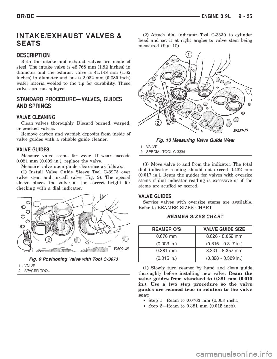
(1) Install Valve Guide Sleeve Tool C-3973 over
valve stem and install valve (Fig. 9). The special
sleeve places the valve at the correct height for
checking with a dial indicator.(2) Attach dial indicator Tool C-3339 to cylinder
head and set it at right angles to valve stem being
measured (Fig. 10).
(3) Move valve to and from the indicator. The total
dial indicator reading should not exceed 0.432 mm
(0.017 in.). Ream the guides for valves with oversize
stems if dial indicator reading is excessive or if the
stems are scuffed or scored.
VALVE GUIDES
Service valves with oversize stems are available.
Refer to REAMER SIZES CHART
REAMER SIZES CHART
REAMER O/S VALVE GUIDE SIZE
0.076 mm 8.026 - 8.052 mm
(0.003 in.) (0.316 - 0.317 in.)
0.381 mm 8.331 - 8.357 mm
(0.015 in.) (0.328 - 0.329 in.)
(1) Slowly turn reamer by hand and clean guide
thoroughly before installing new valve.Ream the
valve guides from standard to 0.381 mm (0.015
in.). Use a two step procedure so the valve
guides are reamed true in relation to the valve
seat:
²Step 1ÐReam to 0.0763 mm (0.003 inch).
²Step 2ÐReam to 0.381 mm (0.015 inch).
Fig. 9 Positioning Valve with Tool C-3973
1 - VALVE
2 - SPACER TOOL
Fig. 10 Measuring Valve Guide Wear
1 - VALVE
2 - SPECIAL TOOL C-3339
BR/BEENGINE 3.9L 9 - 25