2001 DODGE RAM turn signal bulb
[x] Cancel search: turn signal bulbPage 522 of 2889
²If both indicator lamps for a heated seat switch
operate, but the heated seat elements do not heat,
refer toHeated Seat Modulein Electronic Control
Modules for the location of the proper heated seat
module diagnosis and testing procedures. Also refer
to the Body Diagnostic Manual for additional diagno-
sis and testing procedures.
²If none of the indicator lamps for both heated
seat switches will operate and the heated seat ele-
ments for both seats do not heat, refer toHeated
Seat Relayin this section for the location of the
proper heated seat relay diagnosis and testing proce-
dures.
²If the an indicator lamp on either heated seat
switch remains illuminated after the heated seat has
been turned Off, refer toHeated Seat Modulein
Electronic Control Modules for the location of the
proper heated seat module diagnosis and testing pro-
cedures. Also refer to the Body Diagnostic Manual for
additional diagnosis and testing procedures.
DRIVER SEAT HEATER
SWITCH
DESCRIPTION
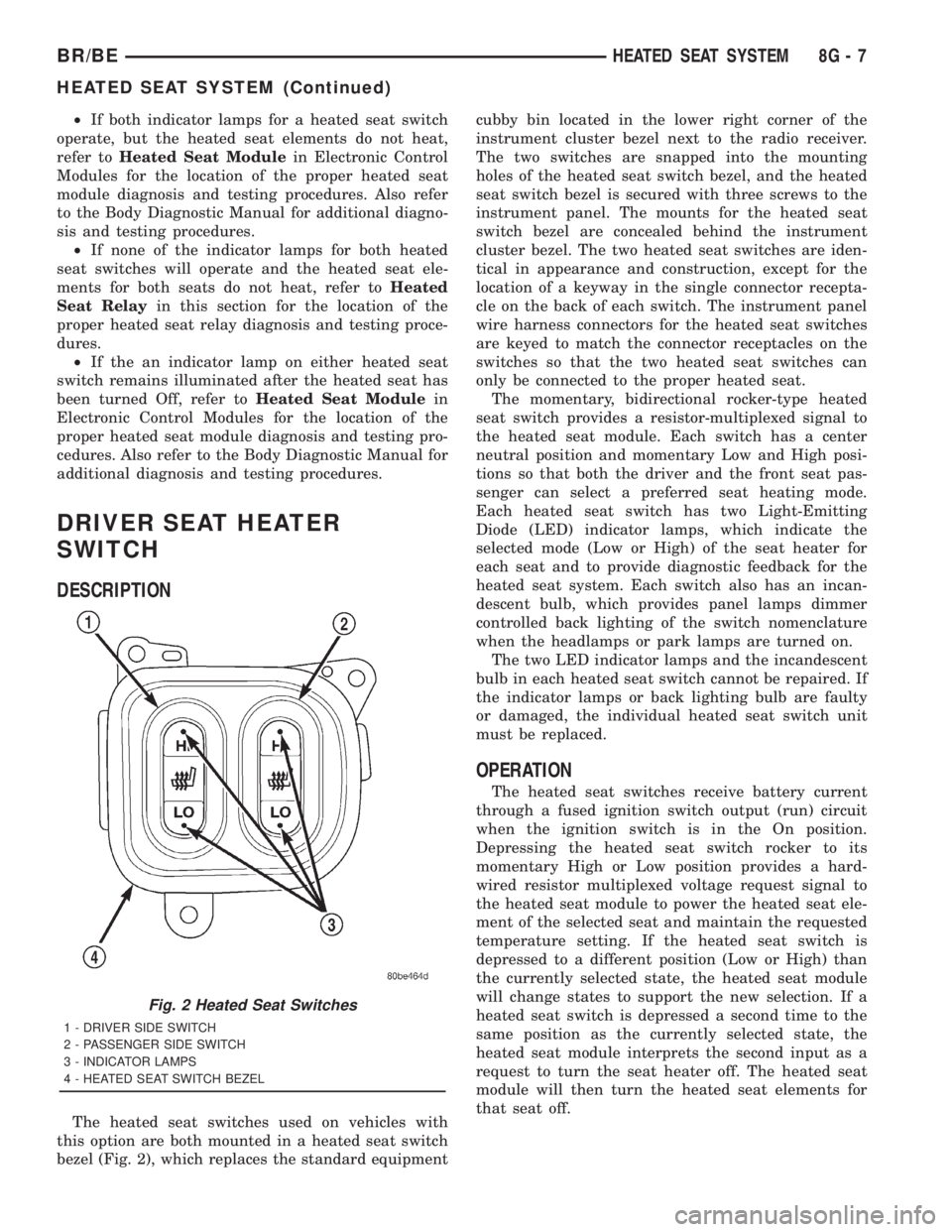
The heated seat switches used on vehicles with
this option are both mounted in a heated seat switch
bezel (Fig. 2), which replaces the standard equipmentcubby bin located in the lower right corner of the
instrument cluster bezel next to the radio receiver.
The two switches are snapped into the mounting
holes of the heated seat switch bezel, and the heated
seat switch bezel is secured with three screws to the
instrument panel. The mounts for the heated seat
switch bezel are concealed behind the instrument
cluster bezel. The two heated seat switches are iden-
tical in appearance and construction, except for the
location of a keyway in the single connector recepta-
cle on the back of each switch. The instrument panel
wire harness connectors for the heated seat switches
are keyed to match the connector receptacles on the
switches so that the two heated seat switches can
only be connected to the proper heated seat.
The momentary, bidirectional rocker-type heated
seat switch provides a resistor-multiplexed signal to
the heated seat module. Each switch has a center
neutral position and momentary Low and High posi-
tions so that both the driver and the front seat pas-
senger can select a preferred seat heating mode.
Each heated seat switch has two Light-Emitting
Diode (LED) indicator lamps, which indicate the
selected mode (Low or High) of the seat heater for
each seat and to provide diagnostic feedback for the
heated seat system. Each switch also has an incan-
descent bulb, which provides panel lamps dimmer
controlled back lighting of the switch nomenclature
when the headlamps or park lamps are turned on.
The two LED indicator lamps and the incandescent
bulb in each heated seat switch cannot be repaired. If
the indicator lamps or back lighting bulb are faulty
or damaged, the individual heated seat switch unit
must be replaced.
OPERATION
The heated seat switches receive battery current
through a fused ignition switch output (run) circuit
when the ignition switch is in the On position.
Depressing the heated seat switch rocker to its
momentary High or Low position provides a hard-
wired resistor multiplexed voltage request signal to
the heated seat module to power the heated seat ele-
ment of the selected seat and maintain the requested
temperature setting. If the heated seat switch is
depressed to a different position (Low or High) than
the currently selected state, the heated seat module
will change states to support the new selection. If a
heated seat switch is depressed a second time to the
same position as the currently selected state, the
heated seat module interprets the second input as a
request to turn the seat heater off. The heated seat
module will then turn the heated seat elements for
that seat off.
Fig. 2 Heated Seat Switches
1 - DRIVER SIDE SWITCH
2 - PASSENGER SIDE SWITCH
3 - INDICATOR LAMPS
4 - HEATED SEAT SWITCH BEZEL
BR/BEHEATED SEAT SYSTEM 8G - 7
HEATED SEAT SYSTEM (Continued)
Page 523 of 2889
The indicator lamps in the heated seat switches
receive battery current through a fused ignition
switch output (run) circuit when the ignition switch
is in the On position. The ground side of each indi-
cator lamp is controlled by a separate (high or low/
driver or passenger) indicator lamp driver circuit by
the heated seat module. The heated seat module con-
trol of the switch indicator lamps also allows the
module to provide diagnostic feedback to the vehicle
operator to indicate monitored heated seat system
faults by flashing the indicator lamps on and off. One
side of the incandescent back lighting bulb in each
heated seat switch is connected to ground at all
times. The other side of the incandescent bulb is con-
nected to the fused panel lamps dimmer switch sig-
nal circuit. These bulbs are energized when the park
lamps or headlamps are turned on, and their illumi-
nation intensity is controlled by the panel lamps dim-
mer switch.
DIAGNOSIS & TESTING - HEATED SEAT
SWITCH
Refer toWiring Diagramsfor the location of com-
plete heated seat system wiring diagrams.
WARNING: ON VEHICLES EQUIPPED WITH AIR-
BAGS, DISABLE THE AIRBAG SYSTEM BEFORE
ATTEMPTING ANY STEERING WHEEL, STEERING
COLUMN, OR INSTRUMENT PANEL COMPONENT
DIAGNOSIS OR SERVICE. DISCONNECT AND ISO-
LATE THE BATTERY NEGATIVE (GROUND) CABLE,
THEN WAIT TWO MINUTES FOR THE AIRBAG SYS-
TEM CAPACITOR TO DISCHARGE BEFORE PER-
FORMING FURTHER DIAGNOSIS OR SERVICE. THIS
IS THE ONLY SURE WAY TO DISABLE THE AIRBAG
SYSTEM. FAILURE TO TAKE THE PROPER PRE-
CAUTIONS COULD RESULT IN ACCIDENTAL AIR-
BAG DEPLOYMENT AND POSSIBLE PERSONAL
INJURY.
(1) If the problem being diagnosed involves inoper-
ative heated seat switch back lighting and the cluster
illumination lamps operate, go to Step 2. If the prob-
lem being diagnosed involves inoperative heated seat
switch back lighting and the cluster illumination
lamps are also inoperative, refer toInstrument
Clusterin the index of this service manual for the
proper cluster illumination lamps diagnosis and test-
ing procedures. If the problem being diagnosed
involves inoperative heated seat switch indicator
lamps and the heated seat elements do not heat,
refer to Step 4. If the problem being diagnosed
involves inoperative heated seat switch indicator
lamps and the heated seat elements do heat, go to
Step 8. If the problem being diagnosed involves a
heated seat switch indicator lamp that remains illu-minated after the heated seat has been turned Off,
refer toHeated Seat Modulein Electronic Control
Modules for the location of the proper heated seat
module diagnosis and testing procedures. Also refer
to the Body Diagnostic Manual for additional diagno-
sis and testing procedures.
(2) Disconnect and isolate the battery negative
cable. Remove the heated seat switch and bezel unit
from the instrument panel. Disconnect the instru-
ment panel wire harness connector from the connec-
tor receptacle on the back of the heated seat switch
to be tested. Check for continuity between the ground
circuit cavity of the instrument panel wire harness
connector for the heated seat switch and a good
ground. There should be continuity. If OK, go to Step
3. If not OK, repair the open ground circuit to ground
as required.
(3) Reconnect the battery negative cable. Turn the
park lamps on with the headlamp switch. Rotate the
panel lamps dimmer thumbwheel on the headlamp
switch upward to just before the interior lamps
detent. Check for battery voltage at the fused panel
lamps dimmer switch signal circuit cavity of the
instrument panel wire harness connector for the
heated seat switch. If OK, replace the faulty heated
seat switch. If not OK, repair the open fused panel
lamps dimmer switch signal circuit to the fuse in the
Junction Block (JB) as required.
(4) Check the fused ignition switch output (run)
fuse in the Junction Block (JB). If OK, go to Step 5.
If not OK, repair the shorted circuit or component as
required and replace the faulty fuse.
(5) Turn the ignition switch to the On position.
Check for battery voltage at the fused ignition switch
output (run) fuse in the JB. If OK, go to Step 6. If
not OK, repair the open fused ignition switch output
(run) circuit to the ignition switch as required.
(6) Disconnect and isolate the battery negative
cable. Remove the heated seat switch and bezel unit
from the instrument panel. Disconnect the instru-
ment panel wire harness connector from the connec-
tor receptacle on the back of the heated seat switch
to be tested. Reconnect the battery negative cable.
Turn the ignition switch to the On position. Check
for battery voltage at the fused ignition switch out-
put (run) circuit cavity of the instrument panel wire
harness connector for the heated seat switch. If OK,
go to Step 7. If not OK, repair the open fused ignition
switch output (run) circuit to the JB fuse as required.
(7) Check the continuity and resistance values of
the heated seat switch in the Neutral, Low and High
positions as shown in the Heated Seat Switch Conti-
nuity chart (Fig. 3). If OK, refer toHeated Seat
Modulein Electronic Control Modules for the loca-
tion of the proper heated seat module diagnosis and
testing procedures. Also refer to the Body Diagnostic
8G - 8 HEATED SEAT SYSTEMBR/BE
DRIVER SEAT HEATER SWITCH (Continued)
Page 529 of 2889
The momentary, bidirectional rocker-type heated
seat switch provides a resistor-multiplexed signal to
the heated seat module. Each switch has a center
neutral position and momentary Low and High posi-
tions so that both the driver and the front seat pas-
senger can select a preferred seat heating mode.
Each heated seat switch has two Light-Emitting
Diode (LED) indicator lamps, which indicate the
selected mode (Low or High) of the seat heater for
each seat and to provide diagnostic feedback for the
heated seat system. Each switch also has an incan-
descent bulb, which provides panel lamps dimmer
controlled back lighting of the switch nomenclature
when the headlamps or park lamps are turned on.
The two LED indicator lamps and the incandescent
bulb in each heated seat switch cannot be repaired. If
the indicator lamps or back lighting bulb are faulty
or damaged, the individual heated seat switch unit
must be replaced.
OPERATION
The heated seat switches receive battery current
through a fused ignition switch output (run) circuit
when the ignition switch is in the On position.
Depressing the heated seat switch rocker to its
momentary High or Low position provides a hard-
wired resistor multiplexed voltage request signal to
the heated seat module to power the heated seat ele-
ment of the selected seat and maintain the requestedtemperature setting. If the heated seat switch is
depressed to a different position (Low or High) than
the currently selected state, the heated seat module
will change states to support the new selection. If a
heated seat switch is depressed a second time to the
same position as the currently selected state, the
heated seat module interprets the second input as a
request to turn the seat heater off. The heated seat
module will then turn the heated seat elements for
that seat off.
The indicator lamps in the heated seat switches
receive battery current through a fused ignition
switch output (run) circuit when the ignition switch
is in the On position. The ground side of each indi-
cator lamp is controlled by a separate (high or low/
driver or passenger) indicator lamp driver circuit by
the heated seat module. The heated seat module con-
trol of the switch indicator lamps also allows the
module to provide diagnostic feedback to the vehicle
operator to indicate monitored heated seat system
faults by flashing the indicator lamps on and off. One
side of the incandescent back lighting bulb in each
heated seat switch is connected to ground at all
times. The other side of the incandescent bulb is con-
nected to the fused panel lamps dimmer switch sig-
nal circuit. These bulbs are energized when the park
lamps or headlamps are turned on, and their illumi-
nation intensity is controlled by the panel lamps dim-
mer switch.
DIAGNOSIS & TESTING - HEATED SEAT
SWITCH
Refer toWiring Diagramsfor the location of com-
plete heated seat system wiring diagrams.
WARNING: ON VEHICLES EQUIPPED WITH AIR-
BAGS, DISABLE THE AIRBAG SYSTEM BEFORE
ATTEMPTING ANY STEERING WHEEL, STEERING
COLUMN, OR INSTRUMENT PANEL COMPONENT
DIAGNOSIS OR SERVICE. DISCONNECT AND ISO-
LATE THE BATTERY NEGATIVE (GROUND) CABLE,
THEN WAIT TWO MINUTES FOR THE AIRBAG SYS-
TEM CAPACITOR TO DISCHARGE BEFORE PER-
FORMING FURTHER DIAGNOSIS OR SERVICE. THIS
IS THE ONLY SURE WAY TO DISABLE THE AIRBAG
SYSTEM. FAILURE TO TAKE THE PROPER PRE-
CAUTIONS COULD RESULT IN ACCIDENTAL AIR-
BAG DEPLOYMENT AND POSSIBLE PERSONAL
INJURY.
(1) If the problem being diagnosed involves inoper-
ative heated seat switch back lighting and the cluster
illumination lamps operate, go to Step 2. If the prob-
lem being diagnosed involves inoperative heated seat
switch back lighting and the cluster illumination
lamps are also inoperative, refer toInstrument
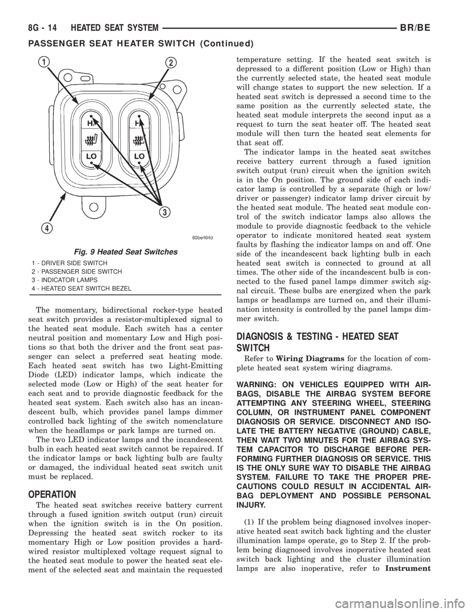
Fig. 9 Heated Seat Switches
1 - DRIVER SIDE SWITCH
2 - PASSENGER SIDE SWITCH
3 - INDICATOR LAMPS
4 - HEATED SEAT SWITCH BEZEL
8G - 14 HEATED SEAT SYSTEMBR/BE
PASSENGER SEAT HEATER SWITCH (Continued)
Page 562 of 2889
²Check Gauges Indicator
²Cruise Indicator (Odometer VFD)
²Four-Wheel Drive Indicator
²High Beam Indicator
²Low Fuel Indicator
²Washer Fluid Indicator
²Malfunction Indicator Lamp (MIL)
²Overdrive-Off Indicator
²Seatbelt Indicator
²Service Reminder Indicator (SRI)
²Transmission Overtemp Indicator
²Turn Signal (Right and Left) Indicators
²Upshift Indicator
²Wait-To-Start Indicator (Diesel Only)
²Water-In-Fuel Indicator (Diesel Only)
Some of these indicators are either programmable
or automatically configured when the EMIC is con-
nected to the vehicle electrical system. This feature
allows those indicators to be activated or deactivated
for compatibility with certain optional equipment.
The EMIC also includes a provision for mounting the
automatic transmission gear selector indicator in the
lower right corner of the cluster. The spring-loaded,
cable driven, mechanical gear selector indicator gives
an indication of the transmission gear that has been
selected with the automatic transmission gear selec-
tor lever. The gear selector indicator pointer is easily
visible through an opening provided in the front of
the cluster overlay, and is also lighted by the cluster
illumination lamps for visibility at night. Models
equipped with a manual transmission have a block-
out plate installed in place of the gear selector indi-
cator.
Cluster illumination is accomplished by adjustable
incandescent back lighting, which illuminates the
gauges for visibility when the exterior lighting is
turned on. The EMIC high beam indicator, turn sig-
nal indicators, and wait-to-start indicator are also
illuminated by dedicated incandescent bulbs. The
remaining indicators in the EMIC are each illumi-
nated by a dedicated Light Emitting Diode (LED)
that is soldered onto the electronic circuit board.
Each of the incandescent bulbs is secured by an inte-
gral bulb holder to the electronic circuit board from
the back of the cluster housing.
Hard wired circuitry connects the EMIC to the
electrical system of the vehicle. These hard wired cir-
cuits are integral to several wire harnesses, which
are routed throughout the vehicle and retained by
many different methods. These circuits may be con-
nected to each other, to the vehicle electrical system
and to the EMIC through the use of a combination of
soldered splices, splice block connectors, and many
different types of wire harness terminal connectors
and insulators. Refer to the appropriate wiring infor-
mation. The wiring information includes wiring dia-grams, proper wire and connector repair procedures,
further details on wire harness routing and reten-
tion, as well as pin-out and location views for the
various wire harness connectors, splices and grounds.
The EMIC modules for this model are serviced only
as complete units. The EMIC module cannot be
adjusted or repaired. If a gauge, an LED indicator,
the VFD, the electronic circuit board, the circuit
board hardware, the cluster overlay, or the EMIC
housing are damaged or faulty, the entire EMIC mod-
ule must be replaced. The cluster lens and hood unit,
the rear cluster housing cover, the automatic trans-
mission gear selector indicator, and the incandescent
lamp bulbs with holders are available for individual
service replacement.
OPERATION
The ElectroMechanical Instrument Cluster (EMIC)
is designed to allow the vehicle operator to monitor
the conditions of many of the vehicle components and
operating systems. The gauges and indicators in the
EMIC provide valuable information about the various
standard and optional powertrains, fuel and emis-
sions systems, cooling systems, lighting systems,
safety systems and many other convenience items.
The EMIC is installed in the instrument panel so
that all of these monitors can be easily viewed by the
vehicle operator when driving, while still allowing
relative ease of access for service. The microproces-
sor-based EMIC hardware and software uses various
inputs to control the gauges and indicators visible on
the face of the cluster. Some of these inputs are hard
wired, but most are in the form of electronic mes-
sages that are transmitted by other electronic mod-
ules over the Chrysler Collision Detection (CCD) data
bus network. (Refer to 8 - ELECTRICAL/ELEC-
TRONIC CONTROL MODULES/COMMUNICATION
- OPERATION).
The EMIC microprocessor smooths the input data
using algorithms to provide gauge readings that are
accurate, stable and responsive to operating condi-
tions. These algorithms are designed to provide
gauge readings during normal operation that are con-
sistent with customer expectations. However, when
abnormal conditions exist, such as low/high battery
voltage, low oil pressure, or high coolant tempera-
ture, the algorithm drives the gauge pointer to an
extreme position and the microprocessor turns on the
Check Gauges indicator to provide a distinct visual
indication of a problem to the vehicle operator. The
instrument cluster circuitry may also generate a
hard wired chime tone request to the Central Timer
Module (CTM) when it monitors certain conditions or
inputs, in order to provide the vehicle operator with
an audible alert.
BR/BEINSTRUMENT CLUSTER 8J - 3
INSTRUMENT CLUSTER (Continued)
Page 564 of 2889
The VFD is diagnosed using the EMIC self-diag-
nostic actuator test. (Refer to 8 - ELECTRICAL/IN-
STRUMENT CLUSTER - DIAGNOSIS AND
TESTING). Proper testing of the CCD data bus and
the data bus message inputs to the EMIC that con-
trol some of the VFD functions requires the use of a
DRBIIItscan tool. Refer to the appropriate diagnos-
tic information. Specific operation details for the
odometer and trip odometer functions of the VFD
may be found elsewhere in this service manual.
INDICATORS
Indicators are located in various positions within
the EMIC and are all connected to the EMIC circuit
board. The four-wheel drive indicator, high beam
indicator, washer fluid indicator, turn signal indica-
tors, and wait-to-start indicator are hard wired. The
brake indicator is controlled by CCD data bus mes-
sages from the Controller Anti-lock Brake (CAB) and
the hard wired park brake switch input to the EMIC.
The seatbelt indicator is controlled by the EMIC pro-
gramming, CCD data bus messages from the Airbag
Control Module (ACM), and the hard wired seat belt
switch input to the EMIC. The Malfunction Indicator
Lamp (MIL) is normally controlled by CCD data bus
messages from the Powertrain Control Module
(PCM); however, if the EMIC loses CCD data bus
communications, the EMIC circuitry will automati-
cally turn the MIL on, and flash the odometer VFD
on and off repeatedly until CCD data bus communi-
cation is restored. The EMIC uses CCD data bus
messages from the Powertrain Control Module
(PCM), the diesel engine only Engine Control Module
(ECM), the ACM, and the CAB to control all of the
remaining indicators. Different indicators are con-
trolled by different strategies; some receive fused
ignition switch output from the EMIC circuitry clus-
ter and have a switched ground, while others are
grounded through the EMIC circuitry and have a
switched battery feed.
In addition, certain indicators in this instrument
cluster are programmable or configurable. This fea-
ture allows the programmable indicators to be acti-
vated or deactivated with a DRBIIItscan tool, while
the configurable indicators will be automatically
enabled or disabled by the EMIC circuitry for com-
patibility with certain optional equipment. The only
programmable indicator for this model is the upshift
indicator. The cruise indicator, four-wheel drive indi-
cator, overdrive-off indicator, service reminder indica-
tor, and the transmission overtemp indicator are
automatically configured, either electronically or
mechanically.The hard wired indicators are diagnosed using con-
ventional diagnostic methods. The EMIC and CCD
bus message controlled indicator lamps are diagnosed
using the EMIC self-diagnostic actuator test. (Refer
to 8 - ELECTRICAL/INSTRUMENT CLUSTER -
DIAGNOSIS AND TESTING). Proper testing of the
CCD data bus and the data bus message inputs to
the EMIC that control each indicator lamp require
the use of a DRBIIItscan tool. Refer to the appro-
priate diagnostic information. Specific operation
details for each indicator may be found elsewhere in
this service manual.
CLUSTER ILLUMINATION
The EMIC has several illumination lamps that are
illuminated when the exterior lighting is turned on
with the headlamp switch. The illumination bright-
ness of these lamps is adjusted by the panel lamps
dimmer rheostat when the headlamp switch thumb-
wheel is rotated (down to dim, up to brighten). The
illumination lamps receive battery current through
the panel lamps dimmer rheostat and a fuse in the
JB on a fused panel lamps dimmer switch signal cir-
cuit. The illumination lamps are grounded at all
times.
In addition, an analog/digital (A/D) converter in
the EMIC converts the analog panel lamps dimmer
rheostat input from the headlamp switch to a digital
dimming level signal for controlling the lighting level
of the VFD. The EMIC also broadcasts this digital
dimming information as a message over the CCD
data bus for use by the Compass Mini-Trip Computer
(CMTC) in synchronizing the lighting level of its
VFD with that of the EMIC. The headlamp switch
thumbwheel also has a Parade position to provide a
parade mode. The EMIC monitors the request for
this mode through a hard wired day brightness sense
circuit input from the headlamp switch. In this mode,
the EMIC will override the selected panel dimmer
switch signal and send a message over the CCD data
bus to illuminate all vacuum fluorescent displays at
full brightness for easier visibility when driving in
daylight with the exterior lighting turned on. The
parade mode has no effect on the incandescent bulb
illumination intensity.
The hard wired cluster illumination lamps are
diagnosed using conventional diagnostic methods.
Proper testing of the VFD dimming level and the
CCD data bus dimming level message functions
requires the use of a DRBIIItscan tool. Refer to the
appropriate diagnostic information.
BR/BEINSTRUMENT CLUSTER 8J - 5
INSTRUMENT CLUSTER (Continued)
Page 569 of 2889
(2) Turn the exterior lamps On with the headlamp
switch. Rotate the headlamp switch panel lamps dim-
mer thumbwheel upward to just before the interior
lamps detent. Check for battery voltage at the panel
lamps dimmer fuse (Fuse5-5ampere) in the JB.
Rotate the panel lamps dimmer thumbwheel down-
ward while observing the test voltmeter. The reading
should go from battery voltage to zero volts. If OK,
go to Step 3. If not OK, repair the open panel lamps
dimmer switch signal circuit between the headlamp
switch and the JB as required.
(3) Turn the exterior lamps Off. Disconnect and
isolate the battery negative cable. Remove the instru-
ment cluster. Remove the instrument panel dimmer
fuse (Fuse5-5ampere) from the JB. Probe the
fused panel lamps dimmer switch signal circuit cav-
ity of the instrument panel wire harness connector
(Connector C2) for the instrument cluster. Check for
continuity to a good ground. There should be no con-
tinuity. If OK, go to Step 4. If not OK, repair the
shorted fused panel lamps dimmer switch signal cir-
cuit between the instrument cluster and the JB as
required.
(4) Reinstall the instrument panel dimmer fuse
(Fuse5-5ampere) in the JB. Reconnect the battery
negative cable. Turn the exterior lamps On with the
headlamp switch. Rotate the headlamp switch panel
lamps dimmer thumbwheel upward to just before the
interior lamps detent. Check for battery voltage at
the fused panel lamps dimmer switch signal circuit
cavity of the instrument panel wire harness connec-
tor (Connector C2) for the instrument cluster. If OK,
replace the faulty bulb and bulb holder units. If not
OK, repair the open fused panel lamps dimmer
switch signal circuit between the instrument cluster
and the JB as required.
REMOVAL
WARNING: ON VEHICLES EQUIPPED WITH AIR-
BAGS, DISABLE THE AIRBAG SYSTEM BEFORE
ATTEMPTING ANY STEERING WHEEL, STEERING
COLUMN, OR INSTRUMENT PANEL COMPONENT
DIAGNOSIS OR SERVICE. DISCONNECT AND ISO-
LATE THE BATTERY NEGATIVE (GROUND) CABLE,
THEN WAIT TWO MINUTES FOR THE AIRBAG SYS-
TEM CAPACITOR TO DISCHARGE BEFORE PER-
FORMING FURTHER DIAGNOSIS OR SERVICE. THIS
IS THE ONLY SURE WAY TO DISABLE THE AIRBAG
SYSTEM. FAILURE TO TAKE THE PROPER PRE-
CAUTIONS COULD RESULT IN ACCIDENTAL AIR-
BAG DEPLOYMENT AND POSSIBLE PERSONAL
INJURY.(1) Disconnect and isolate the battery negative
cable.
(2) Remove the cluster bezel from the instrument
panel. (Refer to 23 - BODY/INSTRUMENT PANEL/
CLUSTER BEZEL - REMOVAL).
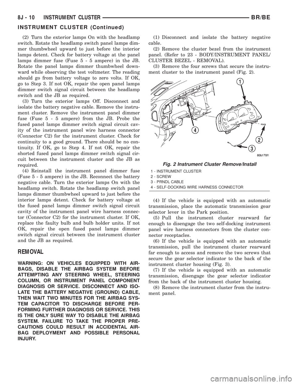
(3) Remove the four screws that secure the instru-
ment cluster to the instrument panel (Fig. 2).
(4) If the vehicle is equipped with an automatic
transmission, place the automatic transmission gear
selector lever in the Park position.
(5) Pull the instrument cluster rearward far
enough to disengage the two self-docking instrument
panel wire harness connectors from the cluster con-
nector receptacles.
(6) If the vehicle is equipped with an automatic
transmission, pull the instrument cluster rearward
far enough to access and remove the two screws that
secure the gear selector indicator to the back of the
instrument cluster housing (Fig. 3).
(7) If the vehicle is equipped with an automatic
transmission, disengage the gear selector indicator
from the back of the instrument cluster housing.
(8) Remove the instrument cluster from the instru-
ment panel.
Fig. 2 Instrument Cluster Remove/Install
1 - INSTRUMENT CLUSTER
2 - SCREW
3 - PRNDL CABLE
4 - SELF-DOCKING WIRE HARNESS CONNECTOR
8J - 10 INSTRUMENT CLUSTERBR/BE
INSTRUMENT CLUSTER (Continued)
Page 591 of 2889

(st-run) circuit whenever the ignition switch is in the
On or Start positions; therefore, the LED will always
be off when the ignition switch is in any position
except On or Start. The LED bulb only illuminates
when it is provided a path to ground by the instru-
ment cluster transistor. The instrument cluster will
turn on the transmission over-temperature indicator
for the following reasons:
²Bulb Test- Each time the ignition switch is
turned to the On position the transmission over-tem-
perature indicator is illuminated for about two sec-
onds as a bulb test.
²Trans Over-Temp Lamp-On Message- Each
time the cluster receives a trans over-temp lamp-on
message from the PCM indicating that the transmis-
sion fluid temperature is 135É C (275É F) or higher,
the indicator will be illuminated and a single chime
tone is sounded. The lamp remains illuminated until
the cluster receives a trans over-temp lamp-off mes-
sage from the PCM, or until the ignition switch is
turned to the Off position, whichever occurs first.
The chime tone feature will only repeat during the
same ignition cycle if the transmission over-tempera-
ture indicator is cycled off and then on again by the
appropriate trans over-temp messages from the PCM.
²Actuator Test- Each time the cluster is put
through the actuator test, the indicator will be
turned on during the bulb check portion of the test to
confirm the functionality of the LED and the cluster
control circuitry.
The PCM continually monitors the transmission
temperature sensor to determine the transmission
operating condition, then sends the proper messages
to the instrument cluster. If the instrument cluster
turns on the transmission over-temperature indicator
due to a high transmission oil temperature condition,
it may indicate that the transmission and/or the
transmission cooling system are being overloaded or
that they require service. For further diagnosis of the
transmission over-temperature indicator or the
instrument cluster circuitry that controls the LED,
(Refer to 8 - ELECTRICAL/INSTRUMENT CLUS-
TER - DIAGNOSIS AND TESTING). For proper
diagnosis of the transmission temperature sensor, the
PCM, the CCD data bus, or the message inputs to
the instrument cluster that control the transmission
over-temperature indicator, a DRBIIItscan tool is
required. Refer to the appropriate diagnostic infor-
mation.
TURN SIGNAL INDICATORS
DESCRIPTION
Two turn signal indicators are standard equipment
on all instrument clusters. The turn signal indicatorsare located near the upper edge of the instrument
cluster overlay, between the speedometer and the
tachometer. Each turn signal indicator consists of a
stenciled cutout of the International Control and Dis-
play Symbol icon for ªTurn Warningº in the opaque
layer of the instrument cluster overlay. The dark
outer layer of the overlay prevents these icons from
being clearly visible when their lamps are not illumi-
nated. The icons appear in green through the trans-
lucent outer layer of the overlay when the indicator
is illuminated from behind by a replaceable incandes-
cent bulb and bulb holder unit located on the instru-
ment cluster electronic circuit board. The turn signal
indicators are serviced as a unit with the instrument
cluster.
OPERATION
The turn signal indicators give an indication to the
vehicle operator that the turn signal (left or right
indicator flashing) or hazard warning (both left and
right indicators flashing) have been selected. These
indicators are controlled by two individual hard
wired inputs to the instrument cluster electronic cir-
cuit board. The turn signal indicator bulbs are
grounded on the instrument cluster electronic circuit
board at all times. The turn signal indicator bulbs
only illuminate when they are provided with battery
current by the turn signal and hazard warning
switch circuitry of the left multi-function switch on
the steering column through separate left and right
turn signal inputs to the instrument cluster; there-
fore, these indicators can be illuminated, regardless
of the ignition switch position.
The turn signal indicators are connected in series
between ground and the output of the turn signal
and hazard warning switch circuitry, but in parallel
with the other turn signal circuits. This arrangement
allows the turn signal indicators to remain functional
regardless of the condition of the other circuits in the
turn signal and hazard warning system. For more
information on the turn signal and hazard warning
system, (Refer to 8 - ELECTRICAL/LAMPS/LIGHT-
ING - EXTERIOR - OPERATION - TURN SIGNAL &
HAZARD WARNING SYSTEM). The turn signal
indicators can be diagnosed using conventional diag-
nostic tools and methods.
DIAGNOSIS AND TESTING - TURN SIGNAL
INDICATORS
The diagnosis found here addresses an inoperative
turn signal indicator lamp condition. If the problem
being diagnosed is related to inoperative turn signals
or hazard warning lamps, be certain to repair the
turn signal and hazard warning system before
attempting to diagnose or repair the turn signal indi-
cators. If no turn signal or hazard warning system
8J - 32 INSTRUMENT CLUSTERBR/BE
TRANSMISSION OVERTEMP INDICATOR (Continued)
Page 592 of 2889
problems are found, the following procedure will help
locate a short or open in the left or right turn signal
indicator circuit. Refer to the appropriate wiring
information. The wiring information includes wiring
diagrams, proper wire and connector repair proce-
dures, details of wire harness routing and retention,
connector pin-out information and location views for
the various wire harness connectors, splices and
grounds.
(1) Disconnect and isolate the battery negative
cable. Remove the instrument cluster.
(2) Connect the battery negative cable. Activate
the hazard warning system by moving the hazard
warning switch button to the On position. Check for
battery voltage at the inoperative (right or left) turn
signal circuit cavity of the instrument panel wire
harness connector (Connector C2) for the instrument
cluster. There should be a switching (on and off) bat-
tery voltage signal. If OK, replace the faulty turn sig-
nal indicator bulb. If not OK, repair the open (right
or left) turn signal circuit to the left multi-function
switch as required.
UPSHIFT INDICATOR
DESCRIPTION
An upshift indicator is standard equipment on all
instrument clusters. However, on vehicles not
equipped with a manual transmission, this indicator
is disabled. The upshift indicator is located near the
fuel gauge in the instrument cluster overlay, to the
left of center. The upshift indicator consists of an
upward pointed arrow icon that is a stenciled cutout
in the opaque layer of the instrument cluster overlay.
The dark outer layer of the overlay prevents the indi-
cator from being clearly visible when it is not illumi-
nated. An amber lens behind the cutout in the
opaque layer of the overlay causes the icon to appear
in amber through the translucent outer layer of the
overlay when the indicator is illuminated from
behind by a replaceable incandescent bulb and bulb
holder unit located on the instrument cluster elec-
tronic circuit board. The upshift indicator is serviced
as a unit with the instrument cluster.
OPERATION
The upshift indicator gives an indication to the
vehicle operator when the transmission should be
shifted to the next highest gear in order to achieve
the best fuel economy. This indicator is controlled by
a transistor on the instrument cluster circuit board
based upon the cluster programming and electronic
messages received by the cluster from the Powertrain
Control Module (PCM) over the Chrysler Collision
Detection (CCD) data bus. The upshift indicator bulbreceives battery current on the instrument cluster
electronic circuit board through the fused ignition
switch output (st-run) circuit whenever the ignition
switch is in the On or Start positions; therefore, the
lamp will always be off when the ignition switch is in
any position except On or Start. The bulb only illu-
minates when it is provided a path to ground by the
instrument cluster transistor. On models not
equipped with a manual transmission, the incandes-
cent bulb and bulb holder unit are not installed at
the factory when the vehicle is built. The instrument
cluster will turn on the upshift indicator for the fol-
lowing reasons:
²Upshift Lamp-On Message- Each time the
cluster receives an upshift lamp-on message from the
PCM indicating the engine speed and load conditions
are right for a transmission upshift to occur, the
upshift indicator is illuminated. The indicator
remains illuminated until the cluster receives an
upshift lamp-off message from the PCM or until the
ignition switch is turned to the Off position, which-
ever occurs first. The PCM will normally send an
upshift lamp-off message three to five seconds after a
lamp-on message, if an upshift is not performed. The
indicator will then remain off until the vehicle stops
accelerating and is brought back into the range of
indicator operation, or until the transmission is
shifted into another gear.
²Actuator Test- Each time the cluster is put
through the actuator test, the indicator will be
turned on during the bulb check portion of the test to
confirm the functionality of the indicator and the
cluster control circuitry.
The PCM continually monitors the engine speed
and load conditions to determine the proper fuel and
ignition requirements. The PCM then sends the
proper messages to the instrument cluster. If the
upshift indicator fails to light during normal vehicle
operation, replace the bulb with a known good unit.
For further diagnosis of the upshift indicator or the
instrument cluster circuitry that controls the indica-
tor, (Refer to 8 - ELECTRICAL/INSTRUMENT
CLUSTER - DIAGNOSIS AND TESTING). For
proper diagnosis of the PCM, the CCD data bus, or
the message inputs to the instrument cluster that
control the upshift indicator, a DRBIIItscan tool is
required. Refer to the appropriate diagnostic infor-
mation.
VOLTAGE GAUGE
DESCRIPTION
A voltage gauge is standard equipment on all
instrument clusters. The voltage gauge is located in
the upper left quadrant of the instrument cluster,
BR/BEINSTRUMENT CLUSTER 8J - 33
TURN SIGNAL INDICATORS (Continued)