2001 DODGE RAM power steering
[x] Cancel search: power steeringPage 371 of 2889
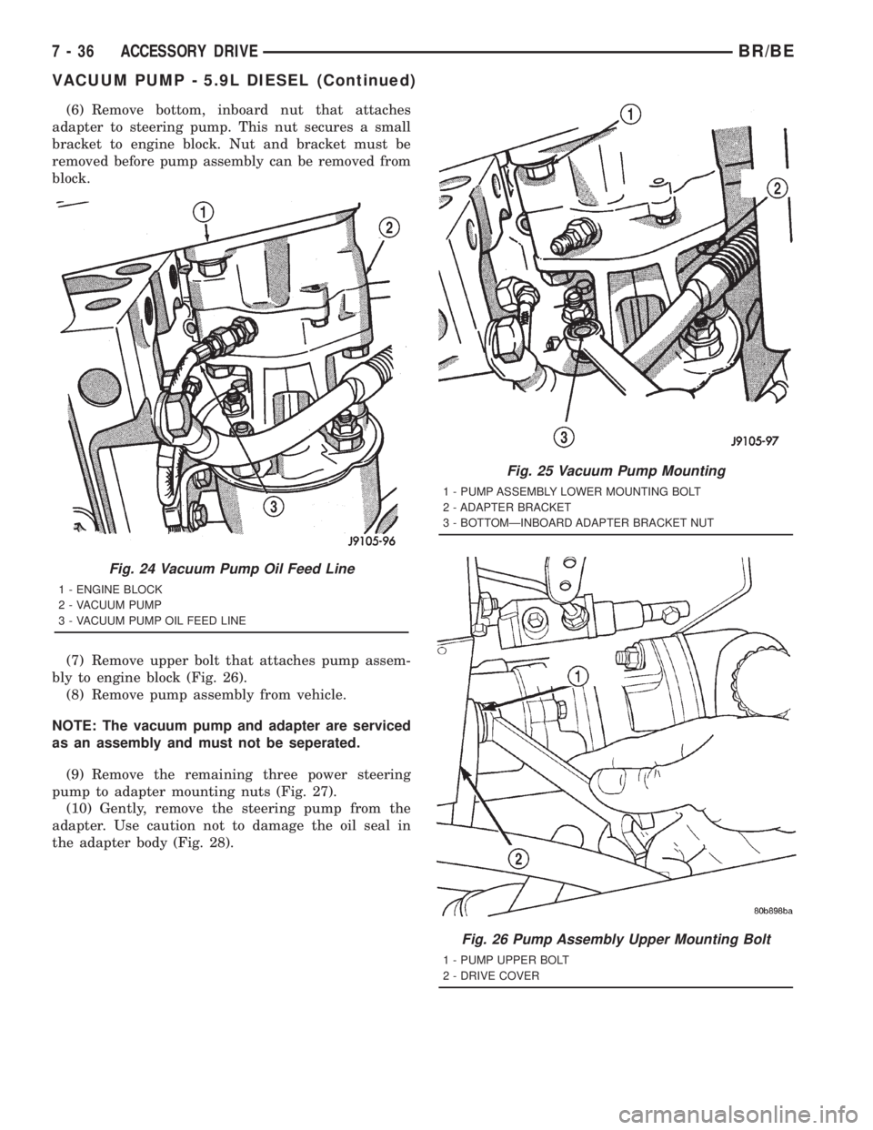
(6) Remove bottom, inboard nut that attaches
adapter to steering pump. This nut secures a small
bracket to engine block. Nut and bracket must be
removed before pump assembly can be removed from
block.
(7) Remove upper bolt that attaches pump assem-
bly to engine block (Fig. 26).
(8) Remove pump assembly from vehicle.
NOTE: The vacuum pump and adapter are serviced
as an assembly and must not be seperated.
(9) Remove the remaining three power steering
pump to adapter mounting nuts (Fig. 27).
(10) Gently, remove the steering pump from the
adapter. Use caution not to damage the oil seal in
the adapter body (Fig. 28).
Fig. 24 Vacuum Pump Oil Feed Line
1 - ENGINE BLOCK
2 - VACUUM PUMP
3 - VACUUM PUMP OIL FEED LINE
Fig. 25 Vacuum Pump Mounting
1 - PUMP ASSEMBLY LOWER MOUNTING BOLT
2 - ADAPTER BRACKET
3 - BOTTOMÐINBOARD ADAPTER BRACKET NUT
Fig. 26 Pump Assembly Upper Mounting Bolt
1 - PUMP UPPER BOLT
2 - DRIVE COVER
7 - 36 ACCESSORY DRIVEBR/BE
VACUUM PUMP - 5.9L DIESEL (Continued)
Page 372 of 2889
INSTALLATION
NOTE: Make sure the two pump spacers are
present before assembling power steering pump to
adapter.
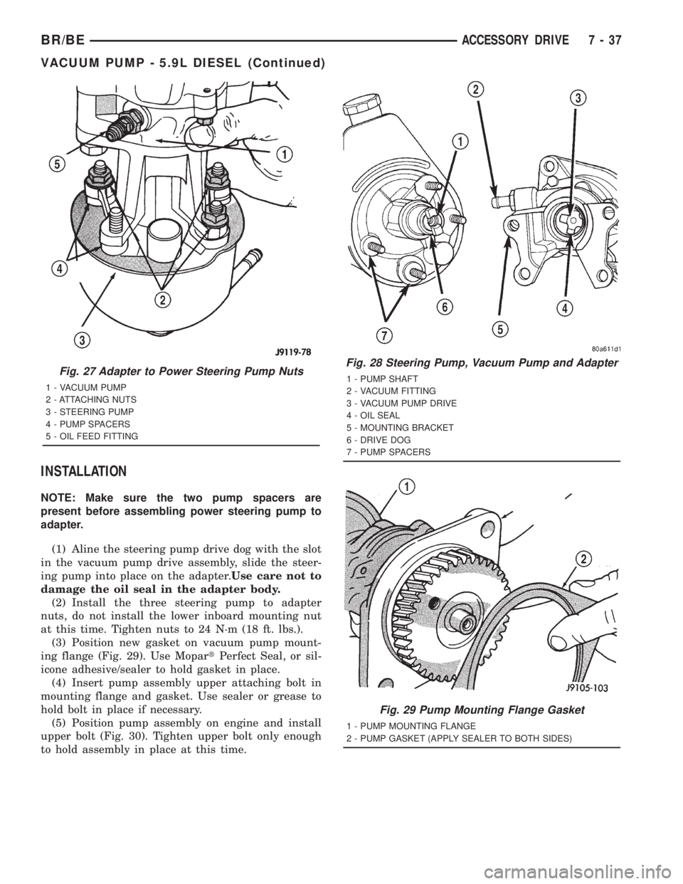
(1) Aline the steering pump drive dog with the slot
in the vacuum pump drive assembly, slide the steer-
ing pump into place on the adapter.Use care not to
damage the oil seal in the adapter body.
(2) Install the three steering pump to adapter
nuts, do not install the lower inboard mounting nut
at this time. Tighten nuts to 24 N´m (18 ft. lbs.).
(3) Position new gasket on vacuum pump mount-
ing flange (Fig. 29). Use MopartPerfect Seal, or sil-
icone adhesive/sealer to hold gasket in place.
(4) Insert pump assembly upper attaching bolt in
mounting flange and gasket. Use sealer or grease to
hold bolt in place if necessary.
(5) Position pump assembly on engine and install
upper bolt (Fig. 30). Tighten upper bolt only enough
to hold assembly in place at this time.
Fig. 27 Adapter to Power Steering Pump Nuts
1 - VACUUM PUMP
2 - ATTACHING NUTS
3 - STEERING PUMP
4 - PUMP SPACERS
5 - OIL FEED FITTING
Fig. 28 Steering Pump, Vacuum Pump and Adapter
1 - PUMP SHAFT
2 - VACUUM FITTING
3 - VACUUM PUMP DRIVE
4 - OIL SEAL
5 - MOUNTING BRACKET
6 - DRIVE DOG
7 - PUMP SPACERS
Fig. 29 Pump Mounting Flange Gasket
1 - PUMP MOUNTING FLANGE
2 - PUMP GASKET (APPLY SEALER TO BOTH SIDES)
BR/BEACCESSORY DRIVE 7 - 37
VACUUM PUMP - 5.9L DIESEL (Continued)
Page 373 of 2889
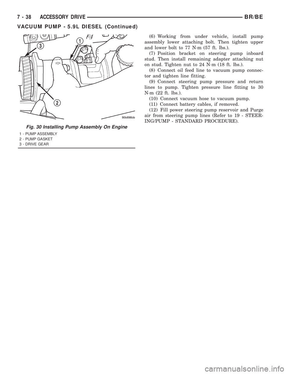
(6) Working from under vehicle, install pump
assembly lower attaching bolt. Then tighten upper
and lower bolt to 77 N´m (57 ft. lbs.).
(7) Position bracket on steering pump inboard
stud. Then install remaining adapter attaching nut
on stud. Tighten nut to 24 N´m (18 ft. lbs.).
(8) Connect oil feed line to vacuum pump connec-
tor and tighten line fitting.
(9) Connect steering pump pressure and return
lines to pump. Tighten pressure line fitting to 30
N´m (22 ft. lbs.).
(10) Connect vacuum hose to vacuum pump.
(11) Connect battery cables, if removed.
(12) Fill power steering pump reservoir and Purge
air from steering pump lines (Refer to 19 - STEER-
ING/PUMP - STANDARD PROCEDURE).
Fig. 30 Installing Pump Assembly On Engine
1 - PUMP ASSEMBLY
2 - PUMP GASKET
3 - DRIVE GEAR
7 - 38 ACCESSORY DRIVEBR/BE
VACUUM PUMP - 5.9L DIESEL (Continued)
Page 386 of 2889
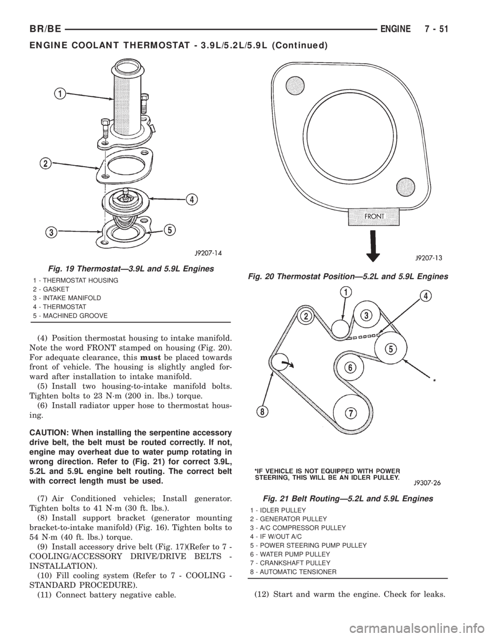
(4) Position thermostat housing to intake manifold.
Note the word FRONT stamped on housing (Fig. 20).
For adequate clearance, thismustbe placed towards
front of vehicle. The housing is slightly angled for-
ward after installation to intake manifold.
(5) Install two housing-to-intake manifold bolts.
Tighten bolts to 23 N´m (200 in. lbs.) torque.
(6) Install radiator upper hose to thermostat hous-
ing.
CAUTION: When installing the serpentine accessory
drive belt, the belt must be routed correctly. If not,
engine may overheat due to water pump rotating in
wrong direction. Refer to (Fig. 21) for correct 3.9L,
5.2L and 5.9L engine belt routing. The correct belt
with correct length must be used.
(7) Air Conditioned vehicles; Install generator.
Tighten bolts to 41 N´m (30 ft. lbs.).
(8) Install support bracket (generator mounting
bracket-to-intake manifold) (Fig. 16). Tighten bolts to
54 N´m (40 ft. lbs.) torque.
(9) Install accessory drive belt (Fig. 17)(Refer to 7 -
COOLING/ACCESSORY DRIVE/DRIVE BELTS -
INSTALLATION).
(10) Fill cooling system (Refer to 7 - COOLING -
STANDARD PROCEDURE).
(11) Connect battery negative cable.(12) Start and warm the engine. Check for leaks.
Fig. 19 ThermostatÐ3.9L and 5.9L Engines
1 - THERMOSTAT HOUSING
2 - GASKET
3 - INTAKE MANIFOLD
4 - THERMOSTAT
5 - MACHINED GROOVEFig. 20 Thermostat PositionÐ5.2L and 5.9L Engines
Fig. 21 Belt RoutingÐ5.2L and 5.9L Engines
1 - IDLER PULLEY
2 - GENERATOR PULLEY
3 - A/C COMPRESSOR PULLEY
4 - IF W/OUT A/C
5 - POWER STEERING PUMP PULLEY
6 - WATER PUMP PULLEY
7 - CRANKSHAFT PULLEY
8 - AUTOMATIC TENSIONER
BR/BEENGINE 7 - 51
ENGINE COOLANT THERMOSTAT - 3.9L/5.2L/5.9L (Continued)
Page 434 of 2889
²Radio memory presets not working properly
²Volume changes with no remote radio switch
input
²Remote radio switch buttons taking on other
functions
²CD player skipping tracks
²Remote radio switch inoperative.
For complete circuit diagrams, refer to the appro-
priate wiring information. The wiring information
includes wiring diagrams, proper wire and connector
repair procedures, details of wire harness routing
and retention, connector pin-out information and
location views for the various wire harness connec-
tors, splices and grounds.
WARNING: ON VEHICLES EQUIPPED WITH AIR-
BAGS, REFER TO ELECTRICAL, RESTRAINTS
BEFORE ATTEMPTING ANY STEERING WHEEL,
STEERING COLUMN, OR INSTRUMENT PANEL
COMPONENT DIAGNOSIS OR SERVICE. FAILURE
TO TAKE THE PROPER PRECAUTIONS COULD
RESULT IN ACCIDENTAL AIRBAG DEPLOYMENT
AND POSSIBLE PERSONAL INJURY.
CAUTION: The speaker output of the radio receiver
is a ªfloating groundº system. Do not allow any
speaker lead to short to ground, as damage to the
radio receiver may result.
(1) Check the fused B(+) fuse in the junction block.
If OK, go to Step 2. If not OK, repair the shorted cir-
cuit or component as required and replace the faulty
fuse.
(2) Check for battery voltage at the fused B(+) fuse
in the junction block. If OK, go to Step 3. If not OK,
repair the open fused B(+) circuit to the Power Dis-
tribution Center (PDC) as required.
(3) Check the fused ignition switch output (acc/
run) fuse in the junction block. If OK, go to Step 4. If
not OK, repair the shorted circuit or component as
required and replace the faulty fuse(s).
(4) Turn the ignition switch to the On position.
Check for battery voltage at the fused ignition switch
output (acc/run) fuse in the junction block. If OK, go
to Step 5. If not OK, repair the open fused ignition
switch output (acc/run) circuit to the ignition switch
as required.
(5) Turn the ignition switch to the Off position.
Disconnect and isolate the battery negative cable.
Remove the radio receiver from the instrument
panel, but do not disconnect the wire harness connec-
tors. Check for continuity between the radio receiver
chassis and a good ground. There should be continu-
ity. If OK, go to Step 6. If not OK, repair the open
ground circuit to ground as required.(6) Connect the battery negative cable. Turn the
ignition switch to the On position. Check for battery
voltage at the fused ignition switch output (acc/run)
circuit cavity of the left (gray) radio wire harness
connector. If OK, go to Step 7. If not OK, repair the
open fused ignition switch output (acc/run) circuit to
the junction block fuse as required.
(7) Turn the ignition switch to the Off position.
Check for battery voltage at the fused B(+) circuit
cavity of the left (gray) radio wire harness connector.
If OK, replace the faulty radio receiver. If not OK,
repair the open fused B(+) circuit to the junction
block fuse as required.
REMOVAL
(1) Disconnect and isolate the battery negative
cable.
(2) Remove the cluster bezel from the instrument
panel.
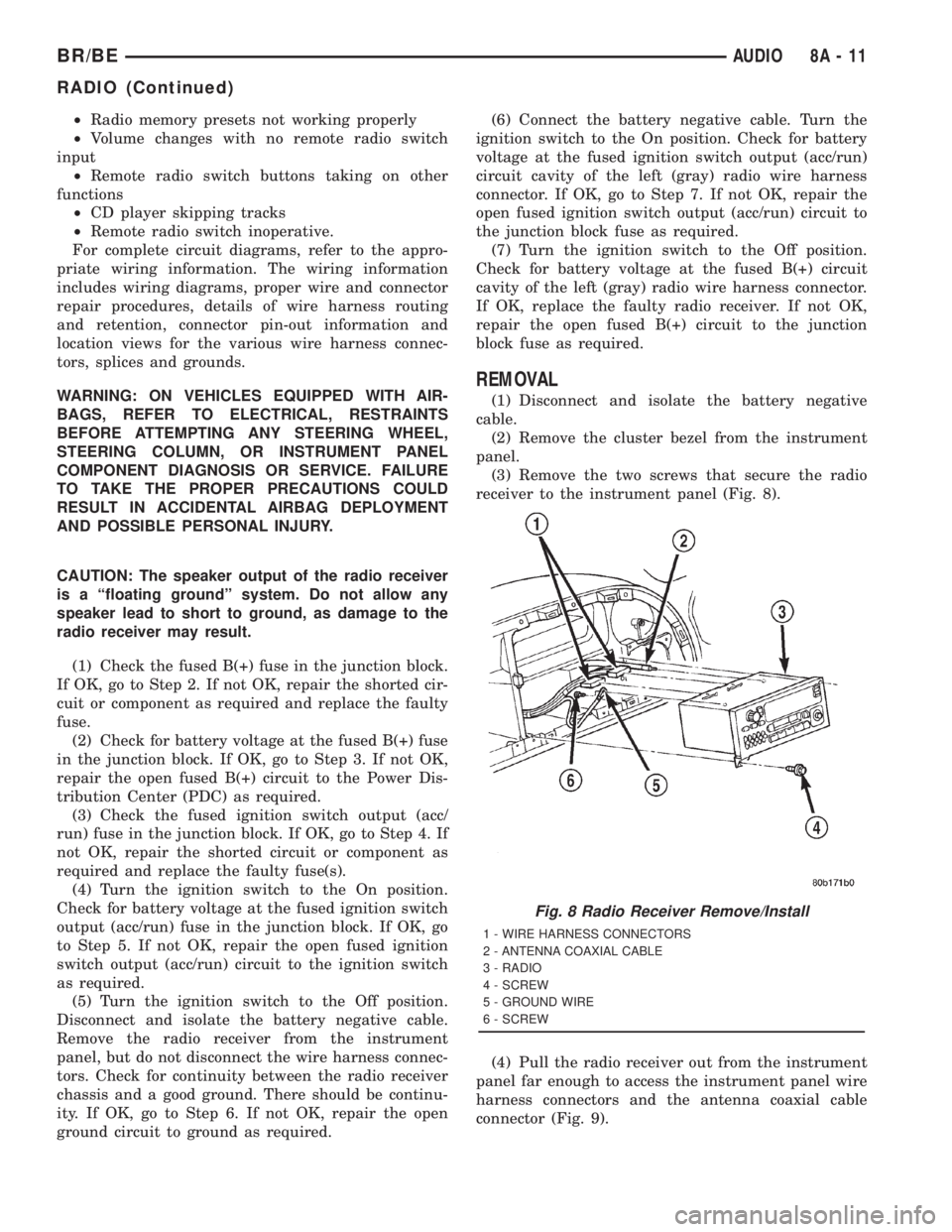
(3) Remove the two screws that secure the radio
receiver to the instrument panel (Fig. 8).
(4) Pull the radio receiver out from the instrument
panel far enough to access the instrument panel wire
harness connectors and the antenna coaxial cable
connector (Fig. 9).
Fig. 8 Radio Receiver Remove/Install
1 - WIRE HARNESS CONNECTORS
2 - ANTENNA COAXIAL CABLE
3 - RADIO
4 - SCREW
5 - GROUND WIRE
6 - SCREW
BR/BEAUDIO 8A - 11
RADIO (Continued)
Page 440 of 2889
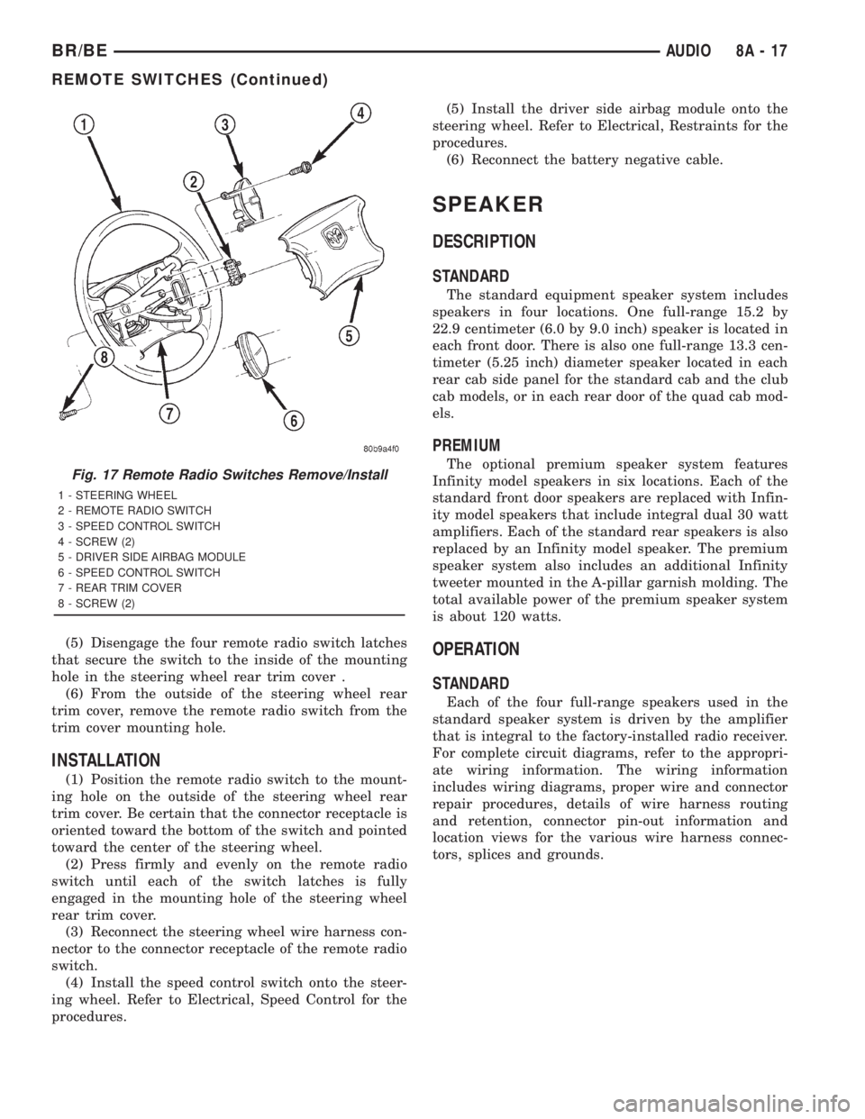
(5) Disengage the four remote radio switch latches
that secure the switch to the inside of the mounting
hole in the steering wheel rear trim cover .
(6) From the outside of the steering wheel rear
trim cover, remove the remote radio switch from the
trim cover mounting hole.
INSTALLATION
(1) Position the remote radio switch to the mount-
ing hole on the outside of the steering wheel rear
trim cover. Be certain that the connector receptacle is
oriented toward the bottom of the switch and pointed
toward the center of the steering wheel.
(2) Press firmly and evenly on the remote radio
switch until each of the switch latches is fully
engaged in the mounting hole of the steering wheel
rear trim cover.
(3) Reconnect the steering wheel wire harness con-
nector to the connector receptacle of the remote radio
switch.
(4) Install the speed control switch onto the steer-
ing wheel. Refer to Electrical, Speed Control for the
procedures.(5) Install the driver side airbag module onto the
steering wheel. Refer to Electrical, Restraints for the
procedures.
(6) Reconnect the battery negative cable.
SPEAKER
DESCRIPTION
STANDARD
The standard equipment speaker system includes
speakers in four locations. One full-range 15.2 by
22.9 centimeter (6.0 by 9.0 inch) speaker is located in
each front door. There is also one full-range 13.3 cen-
timeter (5.25 inch) diameter speaker located in each
rear cab side panel for the standard cab and the club
cab models, or in each rear door of the quad cab mod-
els.
PREMIUM
The optional premium speaker system features
Infinity model speakers in six locations. Each of the
standard front door speakers are replaced with Infin-
ity model speakers that include integral dual 30 watt
amplifiers. Each of the standard rear speakers is also
replaced by an Infinity model speaker. The premium
speaker system also includes an additional Infinity
tweeter mounted in the A-pillar garnish molding. The
total available power of the premium speaker system
is about 120 watts.
OPERATION
STANDARD
Each of the four full-range speakers used in the
standard speaker system is driven by the amplifier
that is integral to the factory-installed radio receiver.
For complete circuit diagrams, refer to the appropri-
ate wiring information. The wiring information
includes wiring diagrams, proper wire and connector
repair procedures, details of wire harness routing
and retention, connector pin-out information and
location views for the various wire harness connec-
tors, splices and grounds.
Fig. 17 Remote Radio Switches Remove/Install
1 - STEERING WHEEL
2 - REMOTE RADIO SWITCH
3 - SPEED CONTROL SWITCH
4 - SCREW (2)
5 - DRIVER SIDE AIRBAG MODULE
6 - SPEED CONTROL SWITCH
7 - REAR TRIM COVER
8 - SCREW (2)
BR/BEAUDIO 8A - 17
REMOTE SWITCHES (Continued)
Page 452 of 2889
ELECTRONIC CONTROL MODULES
TABLE OF CONTENTS
page page
BODY CONTROL/CENTRAL TIMER MODULE
DESCRIPTION............................1
OPERATION.............................3
DIAGNOSIS AND TESTING..................4
CENTRAL TIMER MODULE................4
REMOVAL...............................5
INSTALLATION............................6
COMMUNICATION
DESCRIPTION............................6
OPERATION.............................7
DIAGNOSIS AND TESTING.................11
CCDDATABUS ........................11
CONTROLLER ANTILOCK BRAKE
DESCRIPTION...........................11
OPERATION.............................11REMOVAL..............................12
INSTALLATION...........................12
DATA LINK CONNECTOR
DESCRIPTION...........................12
OPERATION.............................12
ENGINE CONTROL MODULE
DESCRIPTION...........................13
OPERATION.............................13
REMOVAL..............................14
INSTALLATION...........................14
POWERTRAIN CONTROL MODULE
DESCRIPTION...........................14
OPERATION.............................17
REMOVAL..............................19
INSTALLATION...........................20
BODY CONTROL/CENTRAL
TIMER MODULE
DESCRIPTION
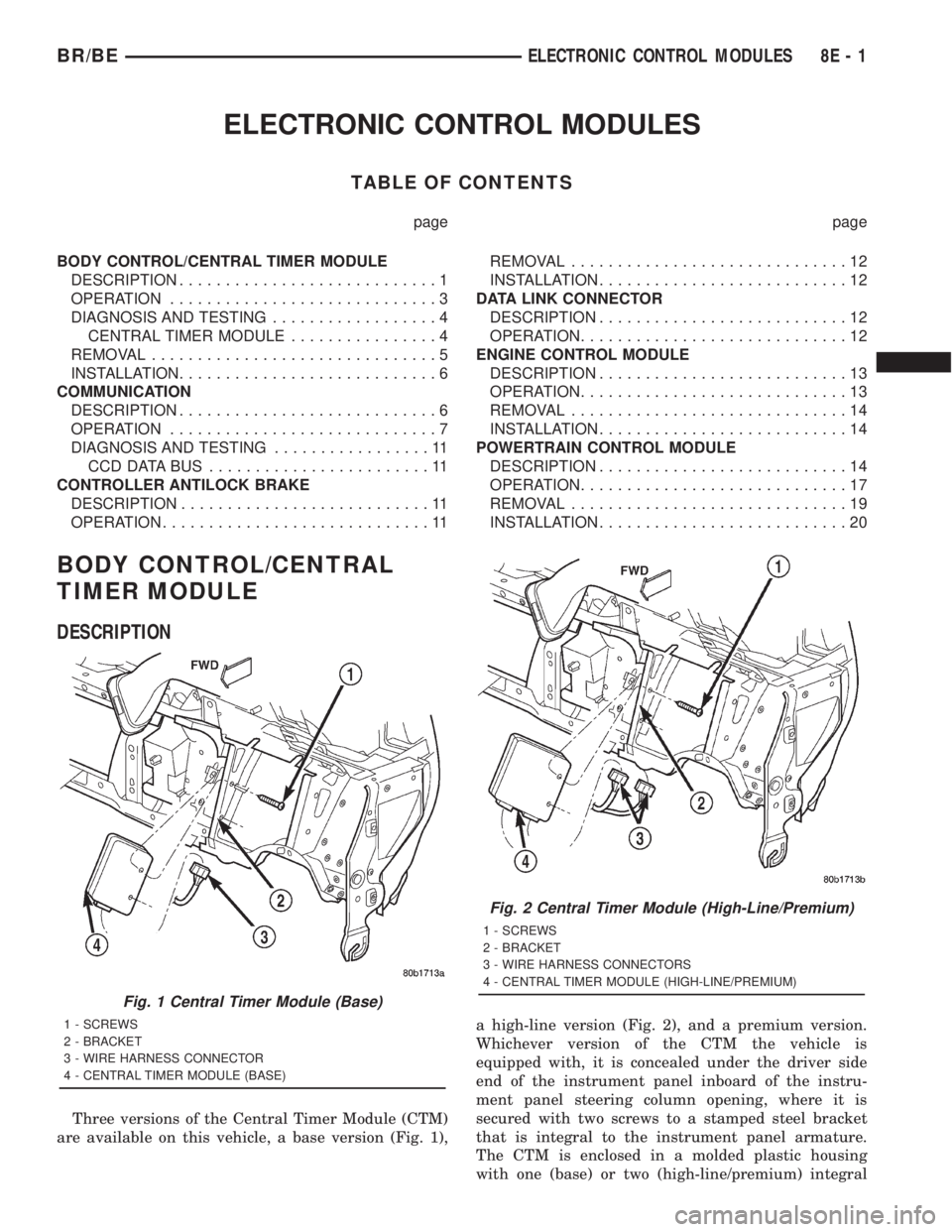
Three versions of the Central Timer Module (CTM)
are available on this vehicle, a base version (Fig. 1),a high-line version (Fig. 2), and a premium version.
Whichever version of the CTM the vehicle is
equipped with, it is concealed under the driver side
end of the instrument panel inboard of the instru-
ment panel steering column opening, where it is
secured with two screws to a stamped steel bracket
that is integral to the instrument panel armature.
The CTM is enclosed in a molded plastic housing
with one (base) or two (high-line/premium) integral
Fig. 1 Central Timer Module (Base)
1 - SCREWS
2 - BRACKET
3 - WIRE HARNESS CONNECTOR
4 - CENTRAL TIMER MODULE (BASE)
Fig. 2 Central Timer Module (High-Line/Premium)
1 - SCREWS
2 - BRACKET
3 - WIRE HARNESS CONNECTORS
4 - CENTRAL TIMER MODULE (HIGH-LINE/PREMIUM)
BR/BEELECTRONIC CONTROL MODULES 8E - 1
Page 454 of 2889

base version of the CTM and the hard wired inputs
or outputs of all CTM versions can be diagnosed
using conventional diagnostic tools and methods;
however, for diagnosis of the high-line or premium
versions of the CTM or the CCD data bus, the use of
a DRBIIItscan tool is required. Refer to the appro-
priate diagnostic information.
OPERATION
The Central Timer Module (CTM) is designed to
control and integrate many of the electronic features
and functions of the vehicle. The base version of the
CTM monitors only hard wired inputs and responds
with the proper hard wired outputs. The microproces-
sor-based high-line/premium version of the CTM
monitors many hard wired switch and sensor inputs
as well as those resources it shares with other elec-
tronic modules in the vehicle through its communica-
tion over the Chrysler Collision Detection (CCD) data
bus network. The internal programming and all of
these inputs allow the high-line/premium CTM
microprocessor to determine the tasks it needs to
perform and their priorities, as well as both the stan-
dard and optional features that it should provide.
The high-line/premium CTM programming then per-
forms those tasks and provides those features
through both CCD data bus communication with
other electronic modules and through hard wired out-
puts to a number of circuits, relays, and actuators.
These outputs allow the high-line/premium CTM the
ability to control numerous accessory systems in the
vehicle.
All versions of the CTM operate on battery current
received through fuses in the Junction Block (JB) on
a non-switched fused B(+) circuit, a fused ignition
switch output (st-run) circuit (base version only), and
a fused ignition switch output (run-acc) circuit (high-
line/premium version only). This arrangement allows
the CTM to provide some features regardless of the
ignition switch position, while other features will
operate only with the ignition switch in the Acces-
sory, On, and/or Start positions. All versions of the
CTM are grounded through their connector and take
out of the instrument panel wire harness. The high-
line/premium CTM has another ground received
through a second connector and take out of the
instrument panel wire harness. The first ground cir-
cuit receives ground through a take out with an eye-
let terminal connector of the instrument panel wire
harness that is secured by a nut to a ground stud
located on the left instrument panel end bracket,
while the second ground circuit (high-line/premium
version only) receives ground through a take out with
an eyelet terminal connector of the instrument panel
wire harness that is secured by a nut to a ground
stud located on the back of the instrument panelarmature above the inboard side of the instrument
panel steering column opening.
The high-line/premium CTM monitors its own
internal circuitry as well as many of its input and
output circuits, and will store a Diagnostic Trouble
Code (DTC) in electronic memory for any failure it
detects. These DTCs can be retrieved and diagnosed
using a DRBIIItscan tool. Refer to the appropriate
diagnostic information.
HARD WIRED INPUTS
The hard wired inputs to the CTM include the fol-
lowing:
²CCD bus± - high-line/premium version only
²CCD bus+ - high-line/premium version only
²Cylinder lock switch mux - high-line premium
version only
²Driver door ajar switch sense
²Fused B(+)
²Fused ignition switch output (run-acc) - high-
line/premium version only
²Fused ignition switch output (st-run) - base ver-
sion only
²Ground (one circuit - base version, two circuits -
high-line/premium version)
²Key-in ignition switch sense
²Passenger door ajar switch sense - high-line/pre-
mium version only
²Power door lock motor B(+) lock - high-line/pre-
mium version only
²Power door lock motor B(+) unlock - high-line/
premium version only
²Radio control mux - high-line/premium version
only
²Tone request signal
²Washer switch sense
²Wiper park switch sense
²Wiper switch mode sense
²Wiper switch mode signal
HARD WIRED OUTPUTS
The hard wired outputs of the CTM include the fol-
lowing:
²CCD bus± - high-line/premium version only
²CCD bus+ - high-line/premium version only
²Courtesy lamp switch output - high-line/pre-
mium version only
²Door lock driver - high-line/premium version
only
²Door unlock driver - high-line/premium version
only
²Headlamp relay control - high-line/premium ver-
sion only
²Heated seat relay control - premium version
only
BR/BEELECTRONIC CONTROL MODULES 8E - 3
BODY CONTROL/CENTRAL TIMER MODULE (Continued)