2001 DODGE RAM power steering
[x] Cancel search: power steeringPage 722 of 2889
er-up mode will also apply if the battery goes dead
while the system is armed, and battery jump-starting
is attempted. The engine no-run feature will prevent
the engine from starting until the alarm system has
been actively or passively disarmed. The VTSS will
be armed until the technician or vehicle operator has
actively or passively disarmed the alarm system. If
the VTSS is in the disarmed mode prior to a battery
disconnect or failure, it will remain disarmed after
the battery is reconnected or replaced, or if jump-
starting is attempted.
TAMPER ALERT
The VTSS tamper alert feature will sound the horn
three times upon disarming, if the alarm was trig-
gered and has since timed-out (about fifteen min-
utes). This feature alerts the vehicle operator that
the VTSS alarm was activated while the vehicle was
unattended.
DIAGNOSIS AND TESTING - VEHICLE THEFT
SECURITY SYSTEM
The VTSS-related hard wired inputs to and out-
puts from the high-line or premium Central Timer
Module (CTM) may be diagnosed and tested using
conventional diagnostic tools and procedures. Refer
to the appropriate wiring information. The wiring
information includes wiring diagrams, proper wire
and connector repair procedures, further details on
wire harness routing and retention, as well as pin-
out and location views for the various wire harness
connectors, splices and grounds.
However, conventional diagnostic methods may not
prove conclusive in the diagnosis of the CTM, the
Powertrain Control Module (PCM), or the Chrysler
Collision Detection (CCD) data bus network. In order
to obtain conclusive testing of the VTSS, the CTM,
the PCM, and the CCD data bus network must also
be checked. The most reliable, efficient, and accurate
means to diagnose the VTSS requires the use of a
DRBIIIž scan tool. Refer to the appropriate diagnos-
tic information. The DRBIIIž scan tool can provide
confirmation that the CCD data bus network is func-
tional, that all of the electronic modules are sending
and receiving the proper messages over the CCD
data bus, and that these modules are receiving the
proper hard wired inputs and responding with the
proper hard wired outputs needed to perform their
functions. See the ªVehicle Theft Security Systemº
menu item on the DRBIIIž scan tool.
WARNING: ON VEHICLES EQUIPPED WITH AIR-
BAGS, DISABLE THE AIRBAG SYSTEM BEFORE
ATTEMPTING ANY STEERING WHEEL, STEERING
COLUMN, OR INSTRUMENT PANEL COMPONENT
DIAGNOSIS OR SERVICE. DISCONNECT AND ISO-LATE THE BATTERY NEGATIVE (GROUND) CABLE,
THEN WAIT TWO MINUTES FOR THE AIRBAG SYS-
TEM CAPACITOR TO DISCHARGE BEFORE PER-
FORMING FURTHER DIAGNOSIS OR SERVICE. THIS
IS THE ONLY SURE WAY TO DISABLE THE AIRBAG
SYSTEM. FAILURE TO TAKE THE PROPER PRE-
CAUTIONS COULD RESULT IN ACCIDENTAL AIR-
BAG DEPLOYMENT AND POSSIBLE PERSONAL
INJURY.
VTSS INDICATOR
DESCRIPTION
The Vehicle Theft Security System (VTSS) indica-
tor consists of a red Light-Emitting Diode (LED)
located on the electronic circuit board of the Compass
Mini-Trip Computer (CMTC) within the overhead
console. The LED extends through a hole in the
CMTC lens located near the forward end of the over-
head console housing near the windshield.
The VTSS indicator cannot be adjusted or repaired
and, if faulty or damaged, the entire CMTC unit
must be replaced. (Refer to 8 - ELECTRICAL/OVER-
HEAD CONSOLE/COMPASS/MINI-TRIP COM-
PUTER - DESCRIPTION).
OPERATION
The Vehicle Theft Security System (VTSS) indica-
tor gives a visible indication of the VTSS arming sta-
tus. One side of Light-Emitting Diode (LED) in the
VTSS indicator is connected to battery current
through a fused B(+) circuit and a fuse in the Junc-
tion Block (JB), so the indicator remains functional
regardless of the ignition switch position. The other
side of the LED is hard wired to the Central Timer
Module (CTM), which controls the operation of the
VTSS indicator by pulling this side of the LED cir-
cuit to ground. When the VTSS arming is in
progress, the CTM will flash the LED rapidly on and
off for about fifteen seconds. When the VTSS has
been successfully armed, the CTM will flash the LED
on and off continually at a much slower rate until
the VTSS has been disarmed. The VTSS indicator
can be diagnosed using conventional diagnostic tools
and methods.
DIAGNOSIS AND TESTING - VTSS INDICATOR
The diagnosis found here addresses an inoperative
Vehicle Theft Security System (VTSS) indicator con-
dition. If the problem being diagnosed is related to
indicator accuracy, be certain to confirm that the
problem is with the indicator and not with an inop-
erative VTSS. (Refer to 8 - ELECTRICAL/VEHICLE
THEFT SECURITY SYSTEM- DIAGNOSIS AND
BR/BEVEHICLE THEFT SECURITY 8Q - 3
VEHICLE THEFT SECURITY (Continued)
Page 723 of 2889
TESTING). If no VTSS problem is found, the follow-
ing procedure will help to locate a short or open in
the VTSS indicator control circuit. Refer to the
appropriate wiring information. The wiring informa-
tion includes wiring diagrams, proper wire and con-
nector repair procedures, details of wire harness
routing and retention, connector pin-out information
and location views for the various wire harness con-
nectors, splices and grounds.
WARNING: ON VEHICLES EQUIPPED WITH AIR-
BAGS, DISABLE THE AIRBAG SYSTEM BEFORE
ATTEMPTING ANY STEERING WHEEL, STEERING
COLUMN, OR INSTRUMENT PANEL COMPONENT
DIAGNOSIS OR SERVICE. DISCONNECT AND ISO-
LATE THE BATTERY NEGATIVE (GROUND) CABLE,
THEN WAIT TWO MINUTES FOR THE AIRBAG SYS-
TEM CAPACITOR TO DISCHARGE BEFORE PER-
FORMING FURTHER DIAGNOSIS OR SERVICE. THIS
IS THE ONLY SURE WAY TO DISABLE THE AIRBAG
SYSTEM. FAILURE TO TAKE THE PROPER PRE-
CAUTIONS COULD RESULT IN ACCIDENTAL AIR-
BAG DEPLOYMENT AND POSSIBLE PERSONAL
INJURY.
(1) Check the fused B(+) fuse (Fuse 12 - 10
ampere) in the Junction Block (JB). If OK, go to Step
2. If not OK, repair the shorted circuit or component
as required and replace the faulty fuse.
(2) Check for battery voltage at the fused B(+) fuse
(Fuse 12 - 10 ampere) in the JB. If OK, go to Step 3.
If not OK, repair the open fused B(+) circuit betweenthe JB and the Power Distribution Center (PDC) as
required.
(3) Disconnect and isolate the battery negative
cable. Disconnect the body wire harness connector for
the Compass Mini-Trip Computer (CMTC) from the
CMTC connector receptacle. Reconnect the battery
negative cable. Check for battery voltage at the fused
B(+) circuit cavity of the body wire harness connector
for the CMTC. If OK, go to Step 4. If not OK, repair
the open fused B(+) circuit between the CMTC indi-
cator and the JB as required.
(4) Disconnect and isolate the battery negative
cable. Disconnect the instrument panel wire harness
connector (Connector C2) for the Central Timer Mod-
ule (CTM) from the CTM connector receptacle. Check
for continuity between the VTSS indicator driver cir-
cuit cavity of the body wire harness connector for the
CMTC and a good ground. There should be no conti-
nuity. If OK, go to Step 5. If not OK, repair the
shorted VTSS indicator driver circuit between the
CMTC and the CTM as required.
(5) Check for continuity between the VTSS indica-
tor driver circuit cavities of the instrument panel
wire harness connector (Connector C2) for the CTM
and the body wire harness connector for the CMTC.
There should be continuity. If OK, replace the faulty
CMTC indicator. If not OK, repair the open VTSS
indicator driver circuit between the CMTC and the
CTM as required.
8Q - 4 VEHICLE THEFT SECURITYBR/BE
VTSS INDICATOR (Continued)
Page 725 of 2889
contains all of the switches for both the wiper and
washer systems.
²Washer Fluid Level Switch- The washer fluid
level switch is located in a dedicated hole on the
lower rear side of the washer reservoir, above the
washer pump/motor unit near the left front corner of
the engine compartment.
²Washer Nozzles- The dual fluidic washer noz-
zles are secured with integral snap features to dedi-
cated openings in the cowl plenum cover/grille panel
located near the base of the windshield. The washer
plumbing fittings for the washer nozzles are con-
cealed beneath the cowl plenum cover/grille panel.
²Washer Pump/Motor- The washer pump/mo-
tor unit is located in a dedicated hole on the lower
rear side of the washer reservoir near the left front
corner of the engine compartment.
²Washer Reservoir- The washer reservoir is
secured to the left side of the radiator fan shroud in
the left front corner of the engine compartment.
²Wiper Arms- The two wiper arms are secured
to the two wiper pivots, which extend through the
cowl plenum cover/grille panel located near the base
of the windshield.
²Wiper Blades- The two wiper blades are
secured to the two wiper arms, and are parked on
the glass near the bottom of the windshield when the
wiper system is not in operation.
²Wiper Module- The wiper pivots are the only
visible components of the wiper module. The remain-
der of the module is concealed within the cowl ple-
num beneath the cowl plenum cover/grille panel. The
wiper module includes the module bracket, the single
wiper motor, the wiper linkage, and the two wiper
pivots.
²Wiper Relay- The wiper relay is located in the
Power Distribution Center (PDC) in the engine com-
partment near the battery.
Features of the wiper and washer system include
the following:
²Continuous Wipe Modes- The two-speed
wiper motor and the internal circuitry of the multi-
function switch work in concert to provide two con-
tinuous wipe cycles, low speed or high speed.
²Intermittent Wipe Mode- The internal cir-
cuitry of the multi-function switch, the CTM, and the
wiper relay work in concert to provide an intermit-
tent wipe mode with multiple delay interval selec-
tions. On models with a high-line or premium CTM,
the CTM also automatically adjusts each manually
selected delay interval to compensate for vehicle
speed.
²Washer Mode- When the washer system is
activated with the multi-function switch while the
wiper system is operating, washer fluid will be dis-
pensed onto the windshield glass through the washernozzles for as long as the washer pump/motor is
energized.
²Wipe-After-Wash Mode- The internal circuitry
of the CTM provides a wipe-after-wash feature
which, if the wipers are turned Off, will operate the
washer pump/motor and the wipers for as long as the
washer system is activated, then provide several
additional wipe cycles after the washer system is
deactivated before parking the wiper blades near the
base of the windshield.
Hard wired circuitry connects the wiper and
washer system components to the electrical system of
the vehicle. These hard wired circuits are integral to
several wire harnesses, which are routed throughout
the vehicle and retained by many different methods.
These circuits may be connected to each other, to the
vehicle electrical system and to the wiper and washer
system components through the use of a combination
of soldered splices, splice block connectors, and many
different types of wire harness terminal connectors
and insulators. Refer to the appropriate wiring infor-
mation. The wiring information includes wiring dia-
grams, proper wire and connector repair procedures,
further details on wire harness routing and reten-
tion, as well as pin-out and location views for the
various wire harness connectors, splices and grounds.
OPERATION
The wiper and washer system is intended to pro-
vide the vehicle operator with a convenient, safe, and
reliable means of maintaining visibility through the
windshield glass. The various components of this sys-
tem are designed to convert electrical energy pro-
duced by the vehicle electrical system into the
mechanical action of the wiper blades to wipe the
outside surface of the glass, as well as into the
hydraulic action of the washer system to apply
washer fluid stored in an on-board reservoir to the
area of the glass to be wiped. When combined, these
components provide the means to effectively main-
tain clear visibility for the vehicle operator by remov-
ing excess accumulations of rain, snow, bugs, mud, or
other minor debris from the outside windshield glass
surface that might be encountered while driving the
vehicle under numerous types of inclement operating
conditions. The vehicle operator initiates all wiper
and washer system functions with the multi-function
switch control stalk that extends from the left side of
the steering column, just below the steering wheel.
Rotating the knob on the end of the multi-function
switch control stalk selects the desired wiper system
operating mode. The wiper system allows the vehicle
operator to select from two continuous wiper speeds,
Hi or Lo, or one of several intermittent wipe Delay
mode intervals. Pushing the button on the end of the
control stalk downwards towards the steering column
8R - 2 WIPERS/WASHERSBR/BE
WIPERS/WASHERS (Continued)
Page 739 of 2889
The wiper relay terminals are connected to the
vehicle electrical system through a connector recepta-
cle in the Power Distribution Center (PDC). The
inputs and outputs of the wiper relay include:
²The common feed terminal (30) is connected to
the wiper motor low speed brush through the wiper
control circuitry of the multi-function switch on the
steering column. When the wiper relay is de-ener-
gized, the common feed terminal is connected to the
wiper park switch output through the wiper park
switch sense circuit. The wiper park switch output
may be battery current (wipers are not parked), or
ground (wipers are parked). When the wiper relay is
energized, the common feed terminal of the wiper is
connected to battery current from a fuse in the Junc-
tion Block (JB) through a fused ignition switch out-
put (run-acc) circuit.
²The coil ground terminal (85) is connected to the
relay control output of the CTM through the wiper
motor relay control circuit. The CTM controls the
ground path for this circuit internally to energize or
de-energize the wiper relay based upon its program-
ming and inputs from the wiper and washer control
circuitry of the multi-function switch and from the
wiper motor park switch.
²The coil battery terminal (86) is connected to
battery current from a fuse in the Junction Block
(JB) through a fused ignition switch output (run-acc)
circuit whenever the ignition switch is in the On or
Accessory positions.
²The normally open terminal (87) is connected to
battery current from a fuse in the Junction Block
(JB) through a fused ignition switch output (run-acc)
circuit whenever the wiper relay control coil is ener-
gized by the CTM. This circuit provides fused igni-
tion switch output (run-acc) current to the wiper
motor low speed brush only when the wiper relay
control coil is energized.
²The normally closed terminal (87A) is connected
to the output of the wiper motor park switch through
the wiper motor park switch sense circuit. This cir-
cuit provides battery current (wipers are not parked)
or ground (wipers are parked) to the wiper motor low
speed brush whenever the wiper relay control coil is
de-energized and the Off position of the wiper control
of the multi-function switch is selected.
The wiper relay can be diagnosed using conven-
tional diagnostic tools and methods.
DIAGNOSIS AND TESTING - WIPER RELAY
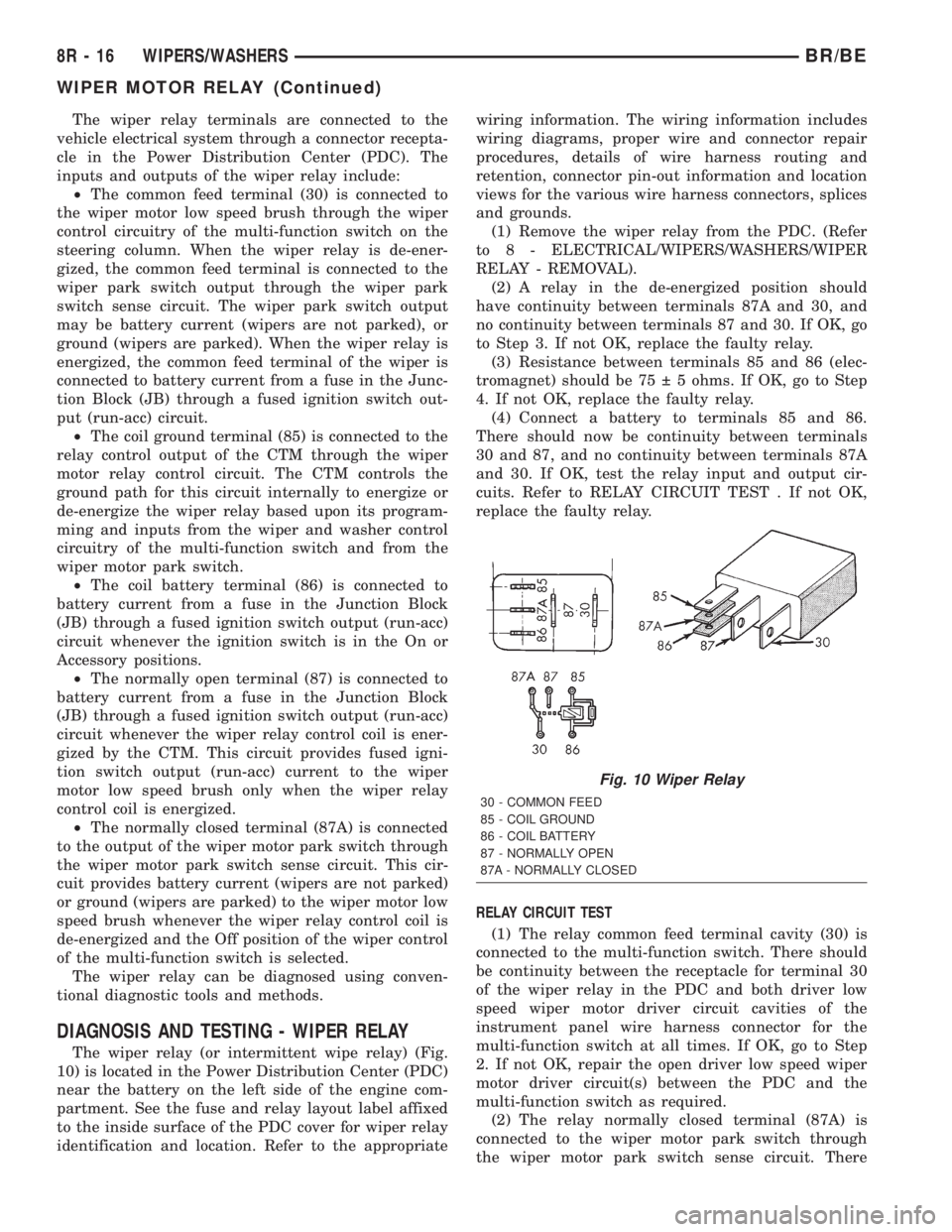
The wiper relay (or intermittent wipe relay) (Fig.
10) is located in the Power Distribution Center (PDC)
near the battery on the left side of the engine com-
partment. See the fuse and relay layout label affixed
to the inside surface of the PDC cover for wiper relay
identification and location. Refer to the appropriatewiring information. The wiring information includes
wiring diagrams, proper wire and connector repair
procedures, details of wire harness routing and
retention, connector pin-out information and location
views for the various wire harness connectors, splices
and grounds.
(1) Remove the wiper relay from the PDC. (Refer
to 8 - ELECTRICAL/WIPERS/WASHERS/WIPER
RELAY - REMOVAL).
(2) A relay in the de-energized position should
have continuity between terminals 87A and 30, and
no continuity between terminals 87 and 30. If OK, go
to Step 3. If not OK, replace the faulty relay.
(3) Resistance between terminals 85 and 86 (elec-
tromagnet) should be 75 5 ohms. If OK, go to Step
4. If not OK, replace the faulty relay.
(4) Connect a battery to terminals 85 and 86.
There should now be continuity between terminals
30 and 87, and no continuity between terminals 87A
and 30. If OK, test the relay input and output cir-
cuits. Refer to RELAY CIRCUIT TEST . If not OK,
replace the faulty relay.
RELAY CIRCUIT TEST
(1) The relay common feed terminal cavity (30) is
connected to the multi-function switch. There should
be continuity between the receptacle for terminal 30
of the wiper relay in the PDC and both driver low
speed wiper motor driver circuit cavities of the
instrument panel wire harness connector for the
multi-function switch at all times. If OK, go to Step
2. If not OK, repair the open driver low speed wiper
motor driver circuit(s) between the PDC and the
multi-function switch as required.
(2) The relay normally closed terminal (87A) is
connected to the wiper motor park switch through
the wiper motor park switch sense circuit. There
Fig. 10 Wiper Relay
30 - COMMON FEED
85 - COIL GROUND
86 - COIL BATTERY
87 - NORMALLY OPEN
87A - NORMALLY CLOSED
8R - 16 WIPERS/WASHERSBR/BE
WIPER MOTOR RELAY (Continued)
Page 1093 of 2889
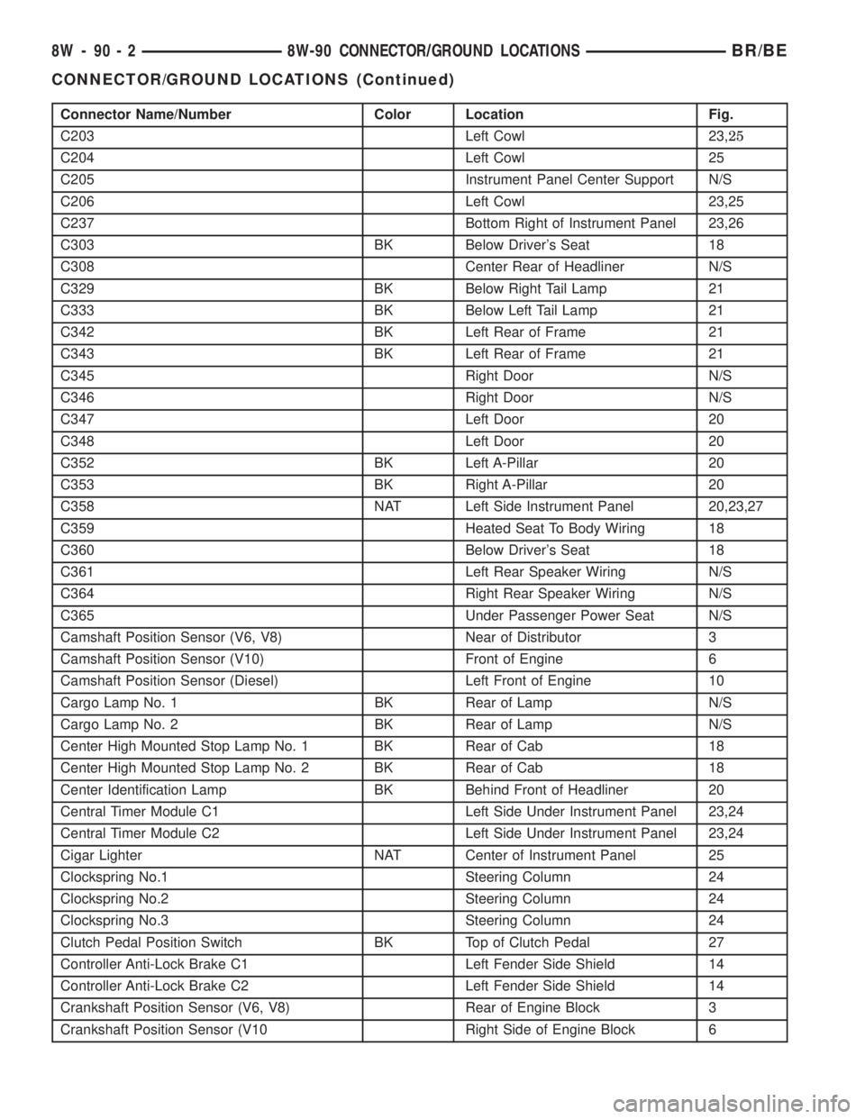
Connector Name/Number Color Location Fig.
C203 Left Cowl 23,25
C204 Left Cowl 25
C205 Instrument Panel Center Support N/S
C206 Left Cowl 23,25
C237 Bottom Right of Instrument Panel 23,26
C303 BK Below Driver's Seat 18
C308 Center Rear of Headliner N/S
C329 BK Below Right Tail Lamp 21
C333 BK Below Left Tail Lamp 21
C342 BK Left Rear of Frame 21
C343 BK Left Rear of Frame 21
C345 Right Door N/S
C346 Right Door N/S
C347 Left Door 20
C348 Left Door 20
C352 BK Left A-Pillar 20
C353 BK Right A-Pillar 20
C358 NAT Left Side Instrument Panel 20,23,27
C359 Heated Seat To Body Wiring 18
C360 Below Driver's Seat 18
C361 Left Rear Speaker Wiring N/S
C364 Right Rear Speaker Wiring N/S
C365 Under Passenger Power Seat N/S
Camshaft Position Sensor (V6, V8) Near of Distributor 3
Camshaft Position Sensor (V10) Front of Engine 6
Camshaft Position Sensor (Diesel) Left Front of Engine 10
Cargo Lamp No. 1 BK Rear of Lamp N/S
Cargo Lamp No. 2 BK Rear of Lamp N/S
Center High Mounted Stop Lamp No. 1 BK Rear of Cab 18
Center High Mounted Stop Lamp No. 2 BK Rear of Cab 18
Center Identification Lamp BK Behind Front of Headliner 20
Central Timer Module C1 Left Side Under Instrument Panel 23,24
Central Timer Module C2 Left Side Under Instrument Panel 23,24
Cigar Lighter NAT Center of Instrument Panel 25
Clockspring No.1 Steering Column 24
Clockspring No.2 Steering Column 24
Clockspring No.3 Steering Column 24
Clutch Pedal Position Switch BK Top of Clutch Pedal 27
Controller Anti-Lock Brake C1 Left Fender Side Shield 14
Controller Anti-Lock Brake C2 Left Fender Side Shield 14
Crankshaft Position Sensor (V6, V8) Rear of Engine Block 3
Crankshaft Position Sensor (V10 Right Side of Engine Block 6
8W - 90 - 2 8W-90 CONNECTOR/GROUND LOCATIONSBR/BE
CONNECTOR/GROUND LOCATIONS (Continued)
Page 1094 of 2889

Connector Name/Number Color Location Fig.
Cummins Bus (-) Left Front of Engine 10
Cup Holder Lamp Center of Instrument Panel 23,26
Data Link Connector BK Left Bottom of Instrument Panel 23,24
Day/Night Mirror BK Day/Night Mirror N/S
Daytime Running Lamp Module BK Left Fender Side Shield 14
Dome Lamp Rear of Cab 18
Driver Airbag BK Steering Wheel N/S
Driver Door Arm/Disarm Switch BK In Door 19
Driver Door Jamb Switch NAT Door Jamb 19
Driver Door Lock Motor BK In Door 19
Driver Door Window/Lock Switch BL In Door 19
Driver Heated Seat Module BL Under Seat N/S
Driver Heated Seat Switch RD Center of Instrument Panel N/S
Driver Lumbar Motor Under Seat N/S
Driver Power Seat Front Vertical Motor BK Under Seat N/S
Driver Power Seat Horizontal Motor BK Under Seat N/S
Driver Power Seat Rear Vertical Motor Under Seat N/S
Driver Power Seat Switch At Seat N/S
Driver Power Window Motor In Door 19
Duty Cycle EVAP/Purge Solenoid BK Right Fender Side Shield 17
Electric Brake Provision Bottom Left of Instrument Panel N/S
Engine Control Module (Diesel) Left Side Engine 12
Engine Coolant Temperature Sensor (Diesel) BK Left Front of Cylinder Head
(Diesel)10
Engine Coolant Temperature Sensor (Gas) BK On Thermostat Housing 3,6
Engine Oil Pressure Sensor (V6, V8) BK Near Distributor 3
Engine Oil Pressure Sensor (V10) Near Oil Filter 6
Engine Oil Pressure Sensor (Diesel) Left Side of Engine 12
Fuel Heater (Diesel) Left Side of Engine 10
Fuel Injection Pump (Diesel) Left Side of Engine, Below ECM 10
Fuel Injector No.1 BK At Fuel Injector 4,5
Fuel Injector No. 2 BK At Fuel Injector 4,5,6
Fuel Injector No. 3 BK At Fuel Injector 4,5,6
Fuel Injector No. 4 BK At Fuel Injector 4,5,6
Fuel Injector No. 5 BK At Fuel Injector 4,5,6
Fuel Injector No. 6 BK At Fuel Injector 4,5,6
Fuel Injector No. 7 BK At Fuel Injector 4,6
Fuel Injector No. 8 BK At Fuel Injector 4,6
Fuel Injector No. 9 BK At Fuel Injector 6
Fuel Injector No. 10 BK At Fuel Injector 6
Fuel Pump Module LTGY At Frame Rail 22
Fuel Transfer Pump (Diesel) Left Rear of Engine Bottom of
Pump10
BR/BE8W-90 CONNECTOR/GROUND LOCATIONS 8W - 90 - 3
CONNECTOR/GROUND LOCATIONS (Continued)
Page 1095 of 2889
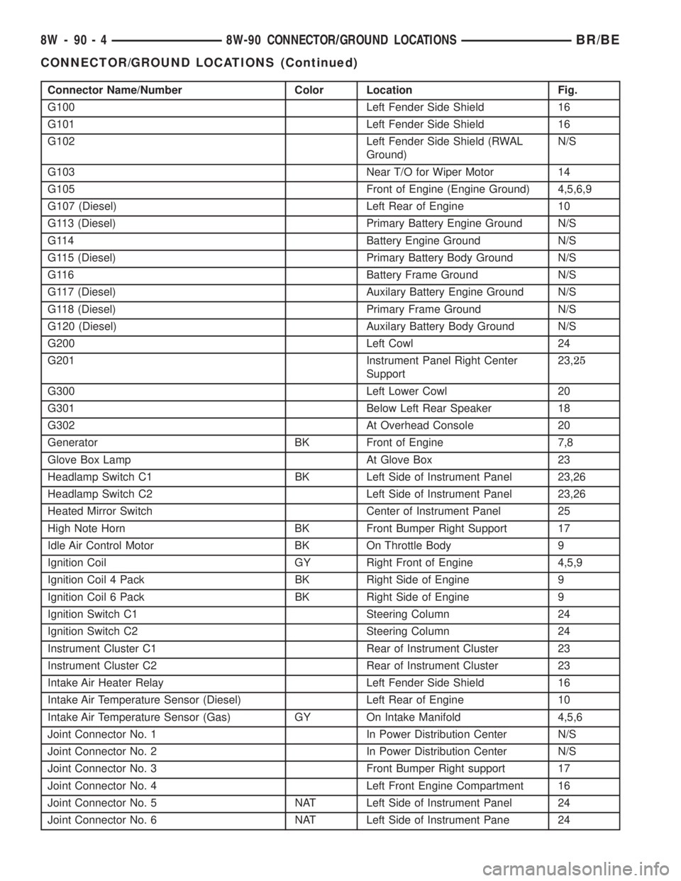
Connector Name/Number Color Location Fig.
G100 Left Fender Side Shield 16
G101 Left Fender Side Shield 16
G102 Left Fender Side Shield (RWAL
Ground)N/S
G103 Near T/O for Wiper Motor 14
G105 Front of Engine (Engine Ground) 4,5,6,9
G107 (Diesel) Left Rear of Engine 10
G113 (Diesel) Primary Battery Engine Ground N/S
G114 Battery Engine Ground N/S
G115 (Diesel) Primary Battery Body Ground N/S
G116 Battery Frame Ground N/S
G117 (Diesel) Auxilary Battery Engine Ground N/S
G118 (Diesel) Primary Frame Ground N/S
G120 (Diesel) Auxilary Battery Body Ground N/S
G200 Left Cowl 24
G201 Instrument Panel Right Center
Support23,25
G300 Left Lower Cowl 20
G301 Below Left Rear Speaker 18
G302 At Overhead Console 20
Generator BK Front of Engine 7,8
Glove Box Lamp At Glove Box 23
Headlamp Switch C1 BK Left Side of Instrument Panel 23,26
Headlamp Switch C2 Left Side of Instrument Panel 23,26
Heated Mirror Switch Center of Instrument Panel 25
High Note Horn BK Front Bumper Right Support 17
Idle Air Control Motor BK On Throttle Body 9
Ignition Coil GY Right Front of Engine 4,5,9
Ignition Coil 4 Pack BK Right Side of Engine 9
Ignition Coil 6 Pack BK Right Side of Engine 9
Ignition Switch C1 Steering Column 24
Ignition Switch C2 Steering Column 24
Instrument Cluster C1 Rear of Instrument Cluster 23
Instrument Cluster C2 Rear of Instrument Cluster 23
Intake Air Heater Relay Left Fender Side Shield 16
Intake Air Temperature Sensor (Diesel) Left Rear of Engine 10
Intake Air Temperature Sensor (Gas) GY On Intake Manifold 4,5,6
Joint Connector No. 1 In Power Distribution Center N/S
Joint Connector No. 2 In Power Distribution Center N/S
Joint Connector No. 3 Front Bumper Right support 17
Joint Connector No. 4 Left Front Engine Compartment 16
Joint Connector No. 5 NAT Left Side of Instrument Panel 24
Joint Connector No. 6 NAT Left Side of Instrument Pane 24
8W - 90 - 4 8W-90 CONNECTOR/GROUND LOCATIONSBR/BE
CONNECTOR/GROUND LOCATIONS (Continued)
Page 1096 of 2889
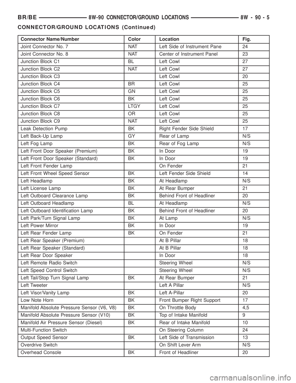
Connector Name/Number Color Location Fig.
Joint Connector No. 7 NAT Left Side of Instrument Pane 24
Joint Connector No. 8 NAT Center of Instrument Panel 23
Junction Block C1 BL Left Cowl 27
Junction Block C2 NAT Left Cowl 27
Junction Block C3 Left Cowl 20
Junction Block C4 BR Left Cowl 25
Junction Block C5 GN Left Cowl 25
Junction Block C6 BK Left Cowl 25
Junction Block C7 LTGY Left Cowl 25
Junction Block C8 OR Left Cowl 25
Junction Block C9 NAT Left Cowl 25
Leak Detection Pump BK Right Fender Side Shield 17
Left Back-Up Lamp GY Rear of Lamp N/S
Left Fog Lamp BK Rear of Fog Lamp N/S
Left Front Door Speaker (Premium) BK In Door 19
Left Front Door Speaker (Standard) BK In Door 19
Left Front Fender Lamp On Fender 21
Left Front Wheel Speed Sensor BK Left Fender Side Shield 14
Left Headlamp BK At Headlamp N/S
Left License Lamp BK At Rear Bumper 21
Left Outboard Clearance Lamp BK Behind Front of Headliner 20
Left Outboard Headlamp BL At Headlamp N/S
Left Outboard Identification Lamp BK Behind Front of Headliner 20
Left Park/Turn Signal Lamp BK At Lamp N/S
Left Power Mirror BK In Door 19
Left Rear Fender Lamp BK On Fender 21
Left Rear Speaker (Premium) At B Pillar 18
Left Rear Speaker (Standard) At B Pillar 18
Left Rear Door Speaker In Door 18
Left Remote Radio Switch Steering Wheel N/S
Left Speed Control Switch Steering Wheel N/S
Left Tail/Stop Turn Signal Lamp BK At Rear Bumper 21
Left Tweeter Left A Pillar N/S
Left Visor/Vanity Lamp BK Left A-Pillar 20
Low Note Horn BK Front Bumper Right Support 17
Manifold Absolute Pressure Sensor (V6, V8) BK On Throttle Body 4,5
Manifold Absolute Pressure Sensor (V10) BK Top of Intake Manifold 9
Manifold Air Pressure Sensor (Diesel) BK Rear of Intake Manifold 10
Multi-Function Switch On Steering Column 24
Output Speed Sensor BK Left Side of Transmission 13
Overdrive Switch On Shift Lever Arm N/S
Overhead Console BK Front of Headliner 20
BR/BE8W-90 CONNECTOR/GROUND LOCATIONS 8W - 90 - 5
CONNECTOR/GROUND LOCATIONS (Continued)