2001 DODGE RAM power steering
[x] Cancel search: power steeringPage 581 of 2889
bol icon for ªHigh Beamº in the opaque layer of the
instrument cluster overlay. The dark outer layer of
the overlay prevents the indicator from being clearly
visible when it is not illuminated. A blue lens behind
the cutout in the opaque layer of the overlay causes
the icon to appear in blue through the translucent
outer layer of the overlay when it is illuminated from
behind by a replaceable incandescent bulb and bulb
holder unit located on the instrument cluster elec-
tronic circuit board. The high beam indicator is ser-
viced as a unit with the instrument cluster.
OPERATION
The high beam indicator gives an indication to the
vehicle operator when the headlamp high beams are
illuminated. This indicator is hard wired on the
instrument cluster electronic circuit board, and is
controlled by a headlamp beam select switch input to
the cluster. The headlamp high beam indicator bulb
receives battery current on the instrument cluster
electronic circuit board through a fused B(+) circuit
at all times; therefore, the indicator remains opera-
tional regardless of the ignition switch position. The
headlamp beam select switch is integral to the multi-
function switch on the left side of the steering col-
umn, and is connected in series between ground and
the headlamp high beam indicator. The indicator
bulb only illuminates when it is provided with a path
to ground through the high beam indicator driver cir-
cuit by the headlamp beam select switch. (Refer to 8
- ELECTRICAL/LAMPS/LIGHTING - EXTERIOR/
MULTI-FUNCTION SWITCH - OPERATION). The
high beam indicator can be diagnosed using conven-
tional diagnostic tools and methods.
DIAGNOSIS AND TESTING - HIGH BEAM
INDICATOR
The diagnosis found here addresses an inoperative
headlamp high beam indicator condition. If the prob-
lem being diagnosed is related to inoperative head-
lamp high beams, be certain to repair the headlamp
system before attempting to diagnose or repair the
high beam indicator. If no headlamp system problems
are found, the following procedure will help locate a
short or open in the high beam indicator circuit.
Refer to the appropriate wiring information. The wir-
ing information includes wiring diagrams, proper
wire and connector repair procedures, details of wire
harness routing and retention, connector pin-out
information and location views for the various wire
harness connectors, splices and grounds.
WARNING: ON VEHICLES EQUIPPED WITH AIR-
BAGS, DISABLE THE AIRBAG SYSTEM BEFORE
ATTEMPTING ANY STEERING WHEEL, STEERING
COLUMN, OR INSTRUMENT PANEL COMPONENTDIAGNOSIS OR SERVICE. DISCONNECT AND ISO-
LATE THE BATTERY NEGATIVE (GROUND) CABLE,
THEN WAIT TWO MINUTES FOR THE AIRBAG SYS-
TEM CAPACITOR TO DISCHARGE BEFORE PER-
FORMING FURTHER DIAGNOSIS OR SERVICE. THIS
IS THE ONLY SURE WAY TO DISABLE THE AIRBAG
SYSTEM. FAILURE TO TAKE THE PROPER PRE-
CAUTIONS COULD RESULT IN ACCIDENTAL AIR-
BAG DEPLOYMENT AND POSSIBLE PERSONAL
INJURY.
INDICATOR DOES NOT ILLUMINATE WITH HIGH BEAMS
SELECTED
(1) Check the fused B(+) fuse (Fuse 14 - 10
ampere) in the Junction Block (JB). If OK, go to Step
2. If not OK, repair the shorted circuit or component
as required and replace the faulty fuse.
(2) Check for battery voltage at the fused B(+) fuse
(Fuse 14 - 10 ampere) in the JB. If OK, go to Step 3.
If not OK, repair the open fused B(+) circuit between
the JB and the Power Distribution Center (PDC) as
required.
(3) Be certain that the headlamp high beams are
selected with the headlamp beam select switch by
turning the headlamp switch to the On position, pull-
ing the multi-function switch stalk toward the steer-
ing wheel, then inspecting the headlamps at the
front of the vehicle. Once the headlamp high beams
are selected, turn the headlamp switch to the Off
position.
(4) Disconnect and isolate the battery negative
cable. Remove the instrument cluster from the
instrument panel. Reconnect the battery negative
cable. Check for battery voltage at the fused B(+) cir-
cuit cavity of the instrument panel wire harness con-
nector (Connector C1) for the instrument cluster. If
OK, go to . If not OK, repair the open fused B(+) cir-
cuit between the instrument cluster and the JB as
required.
(5) Disconnect and isolate the battery negative
cable. Check for continuity between the high beam
indicator driver circuit cavity of the instrument panel
wire harness connector (Connector C2) for the instru-
ment cluster and a good ground. There should be
continuity. If OK, replace the faulty headlamp high
beam indicator bulb and bulb holder unit. If not OK,
repair the open high beam indicator driver circuit
between the instrument cluster and the headlamp
beam select (multi-function) switch as required.
INDICATOR STAYS ILLUMINATED WITH HIGH BEAMS NOT
SELECTED
(1) Be certain that the headlamp low beams are
selected with the headlamp beam select switch by
turning the headlamp switch to the On position, pull-
ing the multi-function switch stalk toward the steer-
8J - 22 INSTRUMENT CLUSTERBR/BE
HIGH BEAM INDICATOR (Continued)
Page 600 of 2889
regardless of the ignition switch position. When the
turn signal (multi-function) switch control stalk is
moved up (right turn) or down (left turn), the turn
signal system is activated. When the turn signal sys-
tem is activated, the circuitry of the turn signal
switch and the combination flasher will cause the
selected (right or left) turn signal indicator, front
park/turn signal lamp, and rear tail/stop/turn signal
lamp to flash on and off. With the hazard warning
(multi-function) switch in the On position, the hazard
warning system is activated. When the hazard warn-
ing system is activated, the circuitry of the hazard
warning switch and the combination flasher will
cause both the right side and the left side turn signal
indicators, front park/turn signal lamps, and rear
tail/stop/turn signal lamps to flash on and off.
Refer to the owner's manual in the vehicle glove
box for more information on the features, use and
operation of the turn signal and hazard warning sys-
tem.
DIAGNOSIS AND TESTING - TURN SIGNAL &
HAZARD WARNING SYSTEM
When diagnosing the turn signal and hazard warn-
ing circuits, remember that high generator output
can burn out bulbs rapidly and repeatedly. If this is a
problem on the vehicle being diagnosed, be certain to
diagnose and repair the charging system as required.
If the problem being diagnosed is related to a failure
of the turn signals to automatically cancel following
completion of a turn, inspect the multi-function
switch for a faulty or damaged cancel actuator and
inspect the turn signal cancel cam on the clockspring
for damaged lobes or improper installation. Refer to
the appropriate wiring information. The wiring infor-
mation includes wiring diagrams, proper wire and
connector repair procedures, details of wire harness
routing and retention, connector pin-out information
and location views for the various wire harness con-
nectors, splices and grounds.
WARNING: ON VEHICLES EQUIPPED WITH AIR-
BAGS, DISABLE THE AIRBAG SYSTEM BEFORE
ATTEMPTING ANY STEERING WHEEL, STEERING
COLUMN, OR INSTRUMENT PANEL COMPONENT
DIAGNOSIS OR SERVICE. DISCONNECT AND ISO-
LATE THE BATTERY NEGATIVE (GROUND) CABLE,
THEN WAIT TWO MINUTES FOR THE AIRBAG SYS-
TEM CAPACITOR TO DISCHARGE BEFORE PER-
FORMING FURTHER DIAGNOSIS OR SERVICE. THIS
IS THE ONLY SURE WAY TO DISABLE THE AIRBAG
SYSTEM. FAILURE TO TAKE THE PROPER PRE-
CAUTIONS COULD RESULT IN ACCIDENTAL AIR-
BAG DEPLOYMENT AND POSSIBLE PERSONAL
INJURY.(1) Turn the ignition switch to the On position.
Actuate the turn signal switch or the hazard warning
switch. Observe the turn signal indicator lamp(s) in
the instrument cluster. If the flash rate is very high,
check for a turn signal bulb that is not lit or is very
dimly lit. Repair the circuits to that lamp or replace
the faulty bulb, as required. If the turn signal indi-
cator(s) fail to light, go to Step 2.
(2) Turn the ignition switch to the Off position.
Check the fused ignition switch output (run-acc) fuse
(Fuse 10 - 10 ampere) in the Junction Block (JB) and
the fused B(+) fuse (Fuse4-20ampere) in the
Power Distribution Center (PDC). If OK, go to Step
3. If not OK, repair the shorted circuit or component
as required and replace the faulty fuse(s).
(3) Check for battery voltage at the fused B(+) fuse
(Fuse4-20ampere) in the PDC. If OK, go to Step 4.
If not OK, repair the open fused B(+) circuit between
the PDC and the battery as required.
(4) Turn the ignition switch to the On position.
Check for battery voltage at the fused ignition switch
output (run-acc) fuse (Fuse 10 - 10 ampere) in the
JB. If OK, go to Step 5. If not OK, repair the open
fused ignition switch output (run-acc) circuit between
the JB and the ignition switch as required.
(5) Turn the ignition switch to the Off position.
Disconnect and isolate the battery negative cable.
Remove the combination flasher from the JB and
replace it with a known good unit. Reconnect the bat-
tery negative cable. Test the operation of the turn
signal and hazard warning systems. If OK, discard
the faulty combination flasher. If not OK, remove the
test flasher and go to Step 6.
(6) Turn the ignition switch to the On position.
Check for battery voltage at the fused ignition switch
output (run-acc) circuit cavity in the JB receptacle
for the combination flasher. If OK, go to Step 7. If
not OK, repair the open fused ignition switch output
(run-acc) circuit between the combination flasher and
the fused ignition switch output (run-acc) fuse (Fuse
10 - 10 ampere) in the JB as required.
(7) Turn the ignition switch to the Off position.
Check for battery voltage at the fused B(+) circuit
cavity of the JB receptacle for the combination
flasher. If OK, go to Step 8. If not OK, repair the
open fused B(+) circuit between the combination
flasher and the fused B(+) fuse (Fuse4-20ampere)
in the PDC as required.
(8) Disconnect and isolate the battery negative
cable. Check for continuity between the ground cir-
cuit cavity of the JB receptacle for the combination
flasher and a good ground. There should be continu-
ity. If OK, go to Step 9. If not OK, repair the open
ground circuit to ground (G201) as required.
BR/BELAMPS/LIGHTING - EXTERIOR 8L - 3
LAMPS/LIGHTING - EXTERIOR (Continued)
Page 615 of 2889
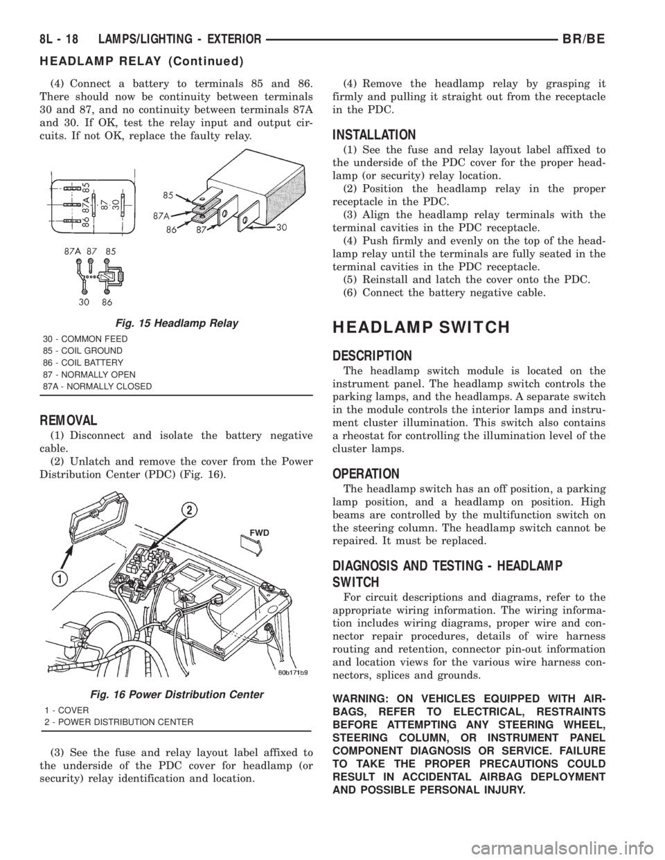
(4) Connect a battery to terminals 85 and 86.
There should now be continuity between terminals
30 and 87, and no continuity between terminals 87A
and 30. If OK, test the relay input and output cir-
cuits. If not OK, replace the faulty relay.
REMOVAL
(1) Disconnect and isolate the battery negative
cable.
(2) Unlatch and remove the cover from the Power
Distribution Center (PDC) (Fig. 16).
(3) See the fuse and relay layout label affixed to
the underside of the PDC cover for headlamp (or
security) relay identification and location.(4) Remove the headlamp relay by grasping it
firmly and pulling it straight out from the receptacle
in the PDC.
INSTALLATION
(1) See the fuse and relay layout label affixed to
the underside of the PDC cover for the proper head-
lamp (or security) relay location.
(2) Position the headlamp relay in the proper
receptacle in the PDC.
(3) Align the headlamp relay terminals with the
terminal cavities in the PDC receptacle.
(4) Push firmly and evenly on the top of the head-
lamp relay until the terminals are fully seated in the
terminal cavities in the PDC receptacle.
(5) Reinstall and latch the cover onto the PDC.
(6) Connect the battery negative cable.
HEADLAMP SWITCH
DESCRIPTION
The headlamp switch module is located on the
instrument panel. The headlamp switch controls the
parking lamps, and the headlamps. A separate switch
in the module controls the interior lamps and instru-
ment cluster illumination. This switch also contains
a rheostat for controlling the illumination level of the
cluster lamps.
OPERATION
The headlamp switch has an off position, a parking
lamp position, and a headlamp on position. High
beams are controlled by the multifunction switch on
the steering column. The headlamp switch cannot be
repaired. It must be replaced.
DIAGNOSIS AND TESTING - HEADLAMP
SWITCH
For circuit descriptions and diagrams, refer to the
appropriate wiring information. The wiring informa-
tion includes wiring diagrams, proper wire and con-
nector repair procedures, details of wire harness
routing and retention, connector pin-out information
and location views for the various wire harness con-
nectors, splices and grounds.
WARNING: ON VEHICLES EQUIPPED WITH AIR-
BAGS, REFER TO ELECTRICAL, RESTRAINTS
BEFORE ATTEMPTING ANY STEERING WHEEL,
STEERING COLUMN, OR INSTRUMENT PANEL
COMPONENT DIAGNOSIS OR SERVICE. FAILURE
TO TAKE THE PROPER PRECAUTIONS COULD
RESULT IN ACCIDENTAL AIRBAG DEPLOYMENT
AND POSSIBLE PERSONAL INJURY.
Fig. 15 Headlamp Relay
30 - COMMON FEED
85 - COIL GROUND
86 - COIL BATTERY
87 - NORMALLY OPEN
87A - NORMALLY CLOSED
Fig. 16 Power Distribution Center
1 - COVER
2 - POWER DISTRIBUTION CENTER
8L - 18 LAMPS/LIGHTING - EXTERIORBR/BE
HEADLAMP RELAY (Continued)
Page 651 of 2889
On those models equipped with the optional RKE
system, the power lock system also includes the fol-
lowing components, which are described in further
detail elsewhere in this service manual:
²Central Timer Module- The high-line or pre-
mium Central Timer Module (CTM) is located under
the driver side end of the instrument panel, inboard
of the instrument panel steering column opening.
The high-line or premium CTM contains a micropro-
cessor and software that allow it to provide the many
electronic functions and features not available with
base version of the power lock system.
²Door Cylinder Lock Switches- A resistor-
multiplexed switch located on the back of each front
door lock cylinder allows the power door lock system
to be operated using a key inserted in either the
driver or passenger front door lock cylinder.
Some of the additional features of the power lock
system found in vehicles with the RKE system option
include:
²Automatic Door Lock- The high-line/premium
CTM provides an optional automatic door lock fea-
ture (also known as rolling door locks). This is a pro-
grammable feature.
²Central Locking- The high-line/premium CTM
provides an optional central locking/unlocking fea-
ture.
²Door Lock Inhibit- The high-line/premium
CTM provides a door lock inhibit feature.
²Enhanced Accident Response- The high-line/
premium CTM provides an optional enhanced acci-
dent response feature. This is a programmable
feature.
Hard wired circuitry connects the power lock sys-
tem components to the electrical system of the vehi-
cle. These hard wired circuits are integral to several
wire harnesses, which are routed throughout the
vehicle and retained by many different methods.
These circuits may be connected to each other, to the
vehicle electrical system and to the power lock sys-
tem components through the use of a combination of
soldered splices, splice block connectors, and many
different types of wire harness terminal connectors
and insulators. Refer to the appropriate wiring infor-
mation. The wiring information includes wiring dia-
grams, proper wire and connector repair procedures,
further details on wire harness routing and reten-
tion, as well as pin-out and location views for the
various wire harness connectors, splices and grounds.
Many of the electronic features in the vehicle con-
trolled or supported by the high-line or premium ver-
sions of the CTM are programmable using the
DRBIIItscan tool. In addition, the high-line/pre-
mium CTM software is Flash compatible, which
means it can be reprogrammed using Flash repro-
gramming procedures. However, if any of the CTMhardware components are damaged or faulty, the
entire CTM unit must be replaced. The power lock
system components and the hard wired inputs or out-
puts of the CTM can be diagnosed using conventional
diagnostic tools and methods; however, for diagnosis
of the high-line or premium versions of the CTM or
the CCD data bus, the use of a DRBIIItscan tool is
required. Refer to the appropriate diagnostic infor-
mation.
DESCRIPTION - REMOTE KEYLESS ENTRY
SYSTEM
A Remote Keyless Entry (RKE) system is an avail-
able option on this model. The Remote Keyless Entry
(RKE) system is a Radio Frequency (RF) system that
allows the remote operation of the power lock system
and, if the vehicle is so equipped, the Vehicle Theft
Security System (VTSS). (Refer to 8 - ELECTRICAL/
VEHICLE THEFT SECURITY - DESCRIPTION).
The RKE system includes the following major compo-
nents, which are described in further detail else-
where in this service manual:
²Central Timer Module- The high-line or pre-
mium Central Timer Module (CTM) is located under
the driver side end of the instrument panel, inboard
of the instrument panel steering column opening.
The high-line or premium CTM contains a micropro-
cessor, an RF receiver, and the software that allow it
to provide the many electronic functions and features
of the RKE system.
²Keyless Entry Transmitter- The keyless
entry transmitter is a small, battery-powered, RF
transmitter that is contained within a molded plastic
case that is designed to also serve as a convenient
key fob.
Some additional features of the RKE system
include:
²Horn Chirp- This feature provides a short,
sharp chirp of the vehicle horn to give an audible
confirmation that a valid Lock signal has been
received from the RKE transmitter. This feature can
be enabled or disabled and, if enabled, one of two
optional horn chirp durations (twenty or forty milli-
seconds) can also be selected.
²Illuminated Entry- This feature turns on the
courtesy lamps in the vehicle for a timed interval
(about thirty seconds) each time a valid Unlock sig-
nal has been received from the RKE transmitter.
²Panic Mode- This feature allows the vehicle
operator to cause the vehicle horn to pulse, the head-
lights to flash, and the courtesy lamps to illuminate
for about three minutes by depressing a Panic button
on the RKE transmitter. Pressing the Panic button a
second time will cancel the Panic mode. A vehicle
speed of about 24 kilometers-per-hour (15 miles-per-
hour) will also cancel the panic mode.
8N - 2 POWER LOCKSBR/BE
POWER LOCKS (Continued)
Page 706 of 2889

SPEED CONTROL
TABLE OF CONTENTS
page page
SPEED CONTROL
DESCRIPTION............................1
OPERATION.............................2
DIAGNOSIS AND TESTING..................2
VACUUM SUPPLY.......................2
ROAD TEST............................3
SPECIFICATIONS.........................4
CABLE
DESCRIPTION............................4
OPERATION.............................4
REMOVAL...............................4
INSTALLATION............................4
SPEED CONTROL SERVO
DESCRIPTION............................5OPERATION.............................5
REMOVAL...............................6
INSTALLATION...........................10
SWITCH
DESCRIPTION...........................12
OPERATION.............................12
REMOVAL..............................13
INSTALLATION...........................13
VACUUM RESERVOIR
DESCRIPTION...........................13
REMOVAL..............................13
INSTALLATION...........................14
SPEED CONTROL
DESCRIPTION - SPEED CONTROL SYSTEM
Gas Engines and/or Diesel With Automatic Trans.
The speed control system is operated by the use of
a cable and a vacuum controlled servo. Electronic
control of the speed control system is integrated into
the Powertrain Control Module (PCM). The controls
consist of two steering wheel mounted switches. The
switches are labeled: ON/OFF, RES/ACCEL, SET,
COAST, and CANCEL.
The system is designed to operate at speeds above
30 mph (50 km/h).
WARNING: THE USE OF SPEED CONTROL IS NOT
RECOMMENDED WHEN DRIVING CONDITIONS DO
NOT PERMIT MAINTAINING A CONSTANT SPEED,
SUCH AS IN HEAVY TRAFFIC OR ON ROADS THAT
ARE WINDING, ICY, SNOW COVERED, OR SLIP-
PERY.
Diesel With Manual Trans.
The speed control system is fully electronically con-
trolled by the Engine Control Module (ECM).A
cable and a vacuum controlled servo are not
used if the vehicle is equipped with a manual
transmission and a diesel engine. This is a ser-
vo-less system.The controls consist of two steering
wheel mounted switches. The switches are labeled:
ON/OFF, RES/ACCEL, SET, COAST, and CANCEL.
The system is designed to operate at speeds above
30 mph (50 km/h).WARNING: THE USE OF SPEED CONTROL IS NOT
RECOMMENDED WHEN DRIVING CONDITIONS DO
NOT PERMIT MAINTAINING A CONSTANT SPEED,
SUCH AS IN HEAVY TRAFFIC OR ON ROADS THAT
ARE WINDING, ICY, SNOW COVERED, OR SLIP-
PERY.
DESCRIPTION - VEHICLE SPEED INPUT
Gas Engines and/or Diesel With Automatic Trans.
The Vehicle Speed Sensor (VSS) is no longer used
for any Dodge Truck.
Vehicle speed and distance covered are measured by
the Rear Wheel Speed Sensor. The sensor is mounted
to the rear axle. A signal is sent from this sensor to the
Controller Antilock Brake (CAB) computer. A signal is
then sent from the CAB to the Powertrain Control
Module (PCM) to determine vehicle speed and distance
covered. The PCM will then determine strategies for
speed control system operation.
Diesel With Manual Trans.
The Vehicle Speed Sensor (VSS) is no longer used
for any Dodge Truck.
Vehicle speed and distance covered are measured
by the Rear Wheel Speed Sensor. The sensor is
mounted to the rear axle. A signal is sent from this
sensor to the Controller Antilock Brake (CAB) com-
puter. A signal is then sent from the CAB to the
Engine Control Module (ECM) to determine vehicle
speed and distance covered. The ECM will then
determine strategies for speed control system opera-
tion.
BR/BESPEED CONTROL 8P - 1
Page 717 of 2889
SWITCH
DESCRIPTION
Gas Engines and Diesel With Auto. Trans.
There are two separate switch pods that operate
the speed control system. The steering-wheel-
mounted switches use multiplexed circuits to provide
inputs to the Powertrain Control Module (PCM) for
ON, OFF, RESUME, ACCELERATE, SET, DECEL
and CANCEL modes. Refer to the owner's manual for
more information on speed control switch functions
and setting procedures.
The individual switches cannot be repaired. If one
switch fails, the entire switch module must be
replaced.
Diesel With Manual Trans.
There are two separate switch pods that operate
the speed control system. The steering-wheel-
mounted switches use multiplexed circuits to provide
inputs to the Engine Control Module (ECM) for ON,
OFF, RESUME, ACCELERATE, SET, DECEL and
CANCEL modes. Refer to the owner's manual for
more information on speed control switch functions
and setting procedures.
The individual switches cannot be repaired. If one
switch fails, the entire switch module must be
replaced.
OPERATION
Gas Engines and Diesel With Auto. Trans.
When speed control is selected by depressing the
ON, OFF switch, the Powertrain Control Module
(PCM) allows a set speed to be stored in its RAM for
speed control. To store a set speed, depress the SET
switch while the vehicle is moving at a speed
between approximately 35 and 85 mph. In order for
the speed control to engage, the brakes cannot be
applied, nor can the gear selector be indicating the
transmission is in Park or Neutral. The speed control
can be disengaged manually by:
²Stepping on the brake pedal
²Depressing the OFF switch
²Depressing the CANCEL switch.The speed con-
trol can be disengaged also by any of the following
conditions:
²An indication of Park or Neutral
²The vehicle speed signal increases at a rate of
10 mph per second (indicates that the co-efficient of
friction between the road surface and tires is
extremely low)
²Depressing the clutch pedal.
²Excessive engine rpm (indicates that the trans-
mission may be in a low gear)²The vehicle speed signal decreases at a rate of
10 mph per second (indicates that the vehicle may
have decelerated at an extremely high rate)
²If the actual speed is not within 20 mph of the
set speedThe previous disengagement conditions are
programmed for added safety.
Once the speed control has been disengaged,
depressing the ACCEL switch restores the vehicle to
the target speed that was stored in the PCM's RAM.
NOTE: Depressing the OFF switch will erase the set
speed stored in the PCM's RAM.
If, while the speed control is engaged, the driver
wishes to increase vehicle speed, the PCM is pro-
grammed for an acceleration feature. With the
ACCEL switch held closed, the vehicle accelerates
slowly to the desired speed. The new target speed is
stored in the PCM's RAM when the ACCEL switch is
released. The PCM also has a9tap-up9feature in
which vehicle speed increases at a rate of approxi-
mately 2 mph for each momentary switch activation
of the ACCEL switch.
The PCM also provides a means to decelerate with-
out disengaging speed control. To decelerate from an
existing recorded target speed, depress and hold the
COAST switch until the desired speed is reached.
Then release the switch. The ON, OFF switch oper-
ates two components: the PCM's ON, OFF input, and
the battery voltage to the brake switch, which powers
the speed control servo.
Diesel With Manual Trans.
When speed control is selected by depressing the
ON, OFF switch, the Engine Control Module (ECM)
allows a set speed to be stored in its RAM for speed
control. To store a set speed, depress the SET switch
while the vehicle is moving at a speed between
approximately 35 and 85 mph. In order for the speed
control to engage, the brakes cannot be applied. The
speed control can be disengaged manually by:
²Stepping on the brake pedal
²Depressing the OFF switch
²Depressing the CANCEL switch.The speed con-
trol can be disengaged also by any of the following
conditions:
²The vehicle speed signal increases at a rate of
10 mph per second (indicates that the co-efficient of
friction between the road surface and tires is
extremely low)
²Depressing the clutch pedal.
²Excessive engine rpm (indicates that the trans-
mission may be in a low gear)
²The vehicle speed signal decreases at a rate of
10 mph per second (indicates that the vehicle may
have decelerated at an extremely high rate)
8P - 12 SPEED CONTROLBR/BE
Page 718 of 2889
²If the actual speed is not within 20 mph of the
set speedThe previous disengagement conditions are
programmed for added safety.
Once the speed control has been disengaged,
depressing the ACCEL switch restores the vehicle to
the target speed that was stored in the ECM's RAM.
NOTE: Depressing the OFF switch will erase the set
speed stored in the ECM's RAM.
If, while the speed control is engaged, the driver
wishes to increase vehicle speed, the ECM is pro-
grammed for an acceleration feature. With the
ACCEL switch held closed, the vehicle accelerates
slowly to the desired speed. The new target speed is
stored in the ECM's RAM when the ACCEL switch is
released. The ECM also has a9tap-up9feature in
which vehicle speed increases at a rate of approxi-
mately 2 mph for each momentary switch activation
of the ACCEL switch.
The ECM also provides a means to decelerate with-
out disengaging speed control. To decelerate from an
existing recorded target speed, depress and hold the
COAST switch until the desired speed is reached.
Then release the switch. The ON, OFF switch oper-
ates two components: the ECM's ON, OFF input, and
the battery voltage to the brake switch, which powers
the speed control servo.
REMOVAL
WARNING: BEFORE BEGINNING ANY AIRBAG SYS-
TEM COMPONENT REMOVAL OR INSTALLATION,
REMOVE AND ISOLATE THE NEGATIVE (-)
CABLE(S) FROM THE BATTERY. THIS IS THE ONLY
SURE WAY TO DISABLE THE AIRBAG SYSTEM.
THEN WAIT TWO MINUTES FOR SYSTEM CAPACI-
TOR TO DISCHARGE BEFORE FURTHER SYSTEM
SERVICE. FAILURE TO DO THIS COULD RESULT IN
ACCIDENTAL AIRBAG DEPLOYMENT AND POSSI-
BLE INJURY.
(1) Disconnect and isolate negative battery
cable(s).
(2) Remove airbag module. Refer to 8, Restraint
Systems for procedures.
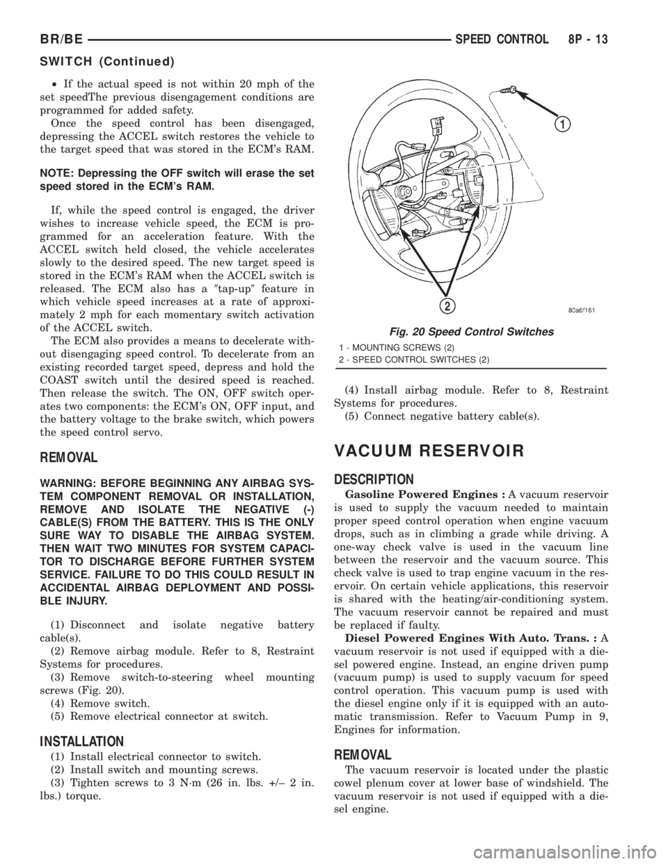
(3) Remove switch-to-steering wheel mounting
screws (Fig. 20).
(4) Remove switch.
(5) Remove electrical connector at switch.
INSTALLATION
(1) Install electrical connector to switch.
(2) Install switch and mounting screws.
(3) Tighten screws to 3 N´m (26 in. lbs. +/± 2 in.
lbs.) torque.(4) Install airbag module. Refer to 8, Restraint
Systems for procedures.
(5) Connect negative battery cable(s).
VACUUM RESERVOIR
DESCRIPTION
Gasoline Powered Engines :A vacuum reservoir
is used to supply the vacuum needed to maintain
proper speed control operation when engine vacuum
drops, such as in climbing a grade while driving. A
one-way check valve is used in the vacuum line
between the reservoir and the vacuum source. This
check valve is used to trap engine vacuum in the res-
ervoir. On certain vehicle applications, this reservoir
is shared with the heating/air-conditioning system.
The vacuum reservoir cannot be repaired and must
be replaced if faulty.
Diesel Powered Engines With Auto. Trans. :A
vacuum reservoir is not used if equipped with a die-
sel powered engine. Instead, an engine driven pump
(vacuum pump) is used to supply vacuum for speed
control operation. This vacuum pump is used with
the diesel engine only if it is equipped with an auto-
matic transmission. Refer to Vacuum Pump in 9,
Engines for information.
REMOVAL
The vacuum reservoir is located under the plastic
cowel plenum cover at lower base of windshield. The
vacuum reservoir is not used if equipped with a die-
sel engine.
Fig. 20 Speed Control Switches
1 - MOUNTING SCREWS (2)
2 - SPEED CONTROL SWITCHES (2)
BR/BESPEED CONTROL 8P - 13
SWITCH (Continued)
Page 720 of 2889
VEHICLE THEFT SECURITY
TABLE OF CONTENTS
page page
VEHICLE THEFT SECURITY
DESCRIPTION............................1
OPERATION.............................2
DIAGNOSIS AND TESTING..................3
VEHICLE THEFT SECURITY SYSTEM........3VTSS INDICATOR
DESCRIPTION............................3
OPERATION.............................3
DIAGNOSIS AND TESTING..................3
VTSS INDICATOR.......................3
VEHICLE THEFT SECURITY
DESCRIPTION
The Vehicle Theft Security System (VTSS) is an
available factory-installed option on this model when
it is also equipped with the high-line or premium
Central Timer Module (CTM). The VTSS is designed
to provide perimeter protection against unauthorized
use or tampering by monitoring the vehicle doors and
the ignition system. If unauthorized vehicle use or
tampering is detected, the system responds by puls-
ing the horn, flashing the headlamps, and preventing
the engine from operating.
The VTSS includes the following major compo-
nents, which are described in further detail else-
where in this service manual:
²Central Timer Module- The high-line or pre-
mium Central Timer Module (CTM) is located under
the driver side end of the instrument panel, inboard
of the instrument panel steering column opening.
The high-line or premium CTM contains a micropro-
cessor and software that allow it to provide many
electronic functions and features not available with
base version of the CTM, including the VTSS. The
CTM provides all of the proper VTSS features and
outputs based upon the monitored inputs. The CTM
circuitry monitors hard wired switch inputs, as well
as message inputs received from other vehicle elec-
tronic modules over the Chrysler Collision Detection
(CCD) data bus network. (Refer to 8 - ELECTRICAL/
ELECTRONIC CONTROL MODULES/BODY CON-
TROL/CENTRAL TIMER MODULE -
DESCRIPTION).
²Door Ajar Switch- A door ajar switch is
located on the hinge pillar of each front door in the
vehicle. These switches provide an input to the VTSS
indicating whether the door is opened or closed.
(Refer to 8 - ELECTRICAL/LAMPS/LIGHTING -
INTERIOR/DOOR AJAR SWITCH - DESCRIPTION).
²Door Cylinder Lock Switch- A door cylinder
lock switch is located on the back of each front door
lock cylinder. This switch provides an input to theVTSS indicating whether the system should remain
armed or be disarmed. (Refer to 8 - ELECTRICAL/
POWER LOCKS/DOOR CYLINDER LOCK SWITCH
- DESCRIPTION).
²Horn Relay- The horn relay is located in the
Power Distribution Center (PDC) in the engine com-
partment near the battery. The horn relay is nor-
mally activated by the horn switch to control the
sounding of the vehicle horn or horns. However, it
can also be activated by an output of the Central
Timer Module (CTM) to provide an audible indication
that unauthorized vehicle use or tampering has been
detected. (Refer to 8 - ELECTRICAL/HORN/HORN
RELAY - DESCRIPTION).
²Headlamp Relay- The headlamp relay (also
known as the security relay) is located in the Power
Distribution Center (PDC) in the engine compart-
ment near the battery. The headlamp relay is nor-
mally activated by the Central Timer Module (CTM)
based upon inputs from the Remote Keyless Entry
(RKE) panic mode feature. However, it can also be
activated by an output of the CTM to flash the head-
lamp low beams to provide a highly visible indication
that unauthorized vehicle use or tampering has been
detected. (Refer to 8 - ELECTRICAL/LAMPS/LIGHT-
ING - EXTERIOR/HEADLAMP RELAY - DESCRIP-
TION).
²VTSS Indicator- A red Light Emitting Diode
(LED) located on the lower surface of the overhead
console near the windshield is illuminated by an out-
put of the Central Timer Module (CTM) to indicate
the status of the VTSS. This LED is integral to the
electronic circuit board for the Compass Mini-Trip
Computer (CMTC). (Refer to 8 - ELECTRICAL/
OVERHEAD CONSOLE/COMPASS/MINI-TRIP
COMPUTER - DESCRIPTION).
The engine no-run feature of the VTSS relies upon
communication between the high-line or premium
CTM and the Powertrain Control Module (PCM) over
the Chrysler Collision Detection (CCD) data bus net-
work.
Hard wired circuitry connects many of the VTSS
components to each other through the electrical sys-
BR/BEVEHICLE THEFT SECURITY 8Q - 1