2001 DODGE RAM clutch
[x] Cancel search: clutchPage 18 of 2889
DESCRIPTION
A multi-purpose, hypoid gear lubricant which con-
forms to the following specifications should be used.
Mopar Hypoid Gear Lubricant conforms to all of
these specifications.
SAE ratings also apply to multiple grade gear
lubricants. In addition, API classification defines the
lubricants usage.
FRONT AXLE
²The lubricant should have MIL-L-2105C and
API GL 5 quality specifications.
²Lubricant is SAE 75W-140 SYNTHETIC gear
lubricant.
REAR AXLE
²The lubricant should have MIL-L-2105C and
API GL 5 quality specifications.
²Lubricant is a thermally stable SAE 80W-90
gear lubricant.
²Lubricant for axles intended for heavy-duty or
trailer tow use is SAE 75W-140 SYNTHETIC gear
lubricant.
NOTE: Trac-lokYand Vari-lokYequipped axles
require a friction modifier be added to the lubricant.
CAUTION: If axle is submerged in water, lubricant
must be replaced immediately to avoid possible
premature axle failure.
DESCRIPTION - TRANSFER CASE FLUID
Recommended lubricant for the NV231 and NV241
transfer case is MopartATF +4, (MS 9602) Auto-
matic Transmission Fluid.
DESCRIPTION - AUTOMATIC TRANSMISSION
FLUID
NOTE: Refer to the maintenance schedules in this
group for the recommended maintenance (fluid/filter
change) intervals for this transmission.
NOTE: Refer to Service Procedures in this group for
fluid level checking procedures.
MopartATF +4, type 9602, Automatic Transmis-
sion Fluid is the recommended fluid for Daimler-
Chrysler automatic transmissions.
Dexron II fluid IS NOT recommended. Clutch
chatter can result from the use of improper
fluid.MopartATF +4, type 9602, Automatic Transmis-
sion Fluid when new is red in color. The ATF is dyed
red so it can be identified from other fluids used in
the vehicle such as engine oil or antifreeze. The red
color is not permanent and is not an indicator of fluid
condition. As the vehicle is driven, the ATF will begin
to look darker in color and may eventually become
brown.This is normal.A dark brown/black fluid
accompanied with a burnt odor and/or deterioration
in shift quality may indicate fluid deterioration or
transmission component failure.
FLUID ADDITIVES
DaimlerChrysler strongly recommends against the
addition of any fluids to the transmission, other than
those automatic transmission fluids listed above.
Exceptions to this policy are the use of special dyes
to aid in detecting fluid leaks.
Various ªspecialº additives and supplements exist
that claim to improve shift feel and/or quality. These
additives and others also claim to improve converter
clutch operation and inhibit overheating, oxidation,
varnish, and sludge. These claims have not been sup-
ported to the satisfaction of DaimlerChrysler and
these additivesmust not be used.The use of trans-
mission ªsealersº should also be avoided, since they
may adversely affect the integrity of transmission
seals.
OPERATION - AUTOMATIC TRANSMISSION
FLUID
The automatic transmission fluid is selected based
upon several qualities. The fluid must provide a high
level of protection for the internal components by
providing a lubricating film between adjacent metal
components. The fluid must also be thermally stable
so that it can maintain a consistent viscosity through
a large temperature range. If the viscosity stays con-
stant through the temperature range of operation,
transmission operation and shift feel will remain con-
sistent. Transmission fluid must also be a good con-
ductor of heat. The fluid must absorb heat from the
internal transmission components and transfer that
heat to the transmission case.
BR/BELUBRICATION & MAINTENANCE 0 - 5
FLUID TYPES (Continued)
Page 87 of 2889
cle turns. A worn pinion mate shaft can also cause a
snapping or a knocking noise.
BEARING NOISE
The axle shaft, differential and pinion bearings can
all produce noise when worn or damaged. Bearing
noise can be either a whining, or a growling sound.
Pinion bearings have a constant-pitch noise. This
noise changes only with vehicle speed. Pinion bearing
noise will be higher pitched because it rotates at a
faster rate. Drive the vehicle and load the differen-
tial. If bearing noise occurs, the rear pinion bearing
is the source of the noise. If the bearing noise is
heard during a coast, the front pinion bearing is the
source.
Worn or damaged differential bearings usually pro-
duce a low pitch noise. Differential bearing noise is
similar to pinion bearing noise. The pitch of differen-
tial bearing noise is also constant and varies only
with vehicle speed.
Axle shaft bearings produce noise and vibration
when worn or damaged. The noise generally changes
when the bearings are loaded. Road test the vehicle.
Turn the vehicle sharply to the left and to the right.
This will load the bearings and change the noise
level. Where axle bearing damage is slight, the noise
is usually not noticeable at speeds above 30 mph.
LOW SPEED KNOCK
Low speed knock is generally caused by a worn
U-joint or by worn side-gear thrust washers. A worn
pinion shaft bore will also cause low speed knock.
VIBRATION
Vibration at the rear of the vehicle is usually
caused by:
²Damaged drive shaft.²Missing drive shaft balance weight(s).
²Worn or out of balance wheels.
²Loose wheel lug nuts.
²Worn U-joint(s).
²Loose/broken springs.
²Damaged axle shaft bearing(s).
²Loose pinion gear nut.
²Excessive pinion yoke run out.
²Bent axle shaft(s).
Check for loose or damaged front end components
or engine/transmission mounts. These components
can contribute to what appears to be a rear end
vibration. Do not overlook engine accessories, brack-
ets and drive belts.
All driveline components should be examined
before starting any repair.
(Refer to 22 - TIRES/WHEELS - DIAGNOSIS AND
TESTING)
DRIVELINE SNAP
A snap or clunk noise when the vehicle is shifted
into gear (or the clutch engaged) can be caused by:
²High engine idle speed.
²Transmission shift operation.
²Loose engine/transmission/transfer case mounts.
²Worn U-joints.
²Loose spring mounts.
²Loose pinion gear nut and yoke.
²Excessive ring gear backlash.
²Excessive side gear to case clearance.
The source of a snap or a clunk noise can be deter-
mined with the assistance of a helper. Raise the vehi-
cle on a hoist with the wheels free to rotate. Instruct
the helper to shift the transmission into gear. Listen
for the noise, a mechanics stethoscope is helpful in
isolating the source of a noise.
3 - 14 FRONT AXLE - 216FBIBR/BE
FRONT AXLE - 216FBI (Continued)
Page 88 of 2889
DIAGNOSTIC CHART
Condition Possible Causes Correction
Wheel Noise 1. Wheel loose. 1. Tighten loose nuts.
2. Faulty, brinelled wheel bearing. 2. Replace bearing.
Axle Shaft Noise 1. Misaligned axle tube. 1. Inspect axle tube alignment. Correct
as necessary.
2. Bent or sprung axle shaft. 2. Inspect and correct as necessary.
3. End-play in pinion bearings. 3. Refer to pinion pre-load information
and correct as necessary.
4. Excessive gear backlash between the
ring gear and pinion.4. Check adjustment of the ring gear
and pinion backlash. Correct as
necessary.
5. Improper adjustment of pinion gear
bearings.5. Adjust the pinion bearings pre-load.
6. Loose pinion yoke nut. 6. Tighten the pinion yoke nut.
7. Scuffed gear tooth contact surfaces. 7. Inspect and replace as necessary.
Axle Shaft Broke 1. Misaligned axle tube. 1. Replace the broken shaft after
correcting tube mis-alignment.
2 Vehicle overloaded. 2. Replace broken shaft and avoid
excessive weight on vehicle.
3. Erratic clutch operation. 3. Replace broken shaft and avoid or
correct erratic clutch operation.
4. Grabbing clutch. 4. Replace broken shaft and inspect and
repair clutch as necessary.
Differential Cracked 1. Improper adjustment of the
differential bearings.1. Replace case and inspect gears and
bearings for further damage. Set
differential bearing pre-load properly.
2. Excessive ring gear backlash. 2. Replace case and inspect gears and
bearings for further damage. Set ring
gear backlash properly.
3. Vehicle overloaded. 3. Replace case and inspect gears and
bearings for further damage. Avoid
excessive vehicle weight.
4. Erratic clutch operation. 4. Replace case and inspect gears and
bearings for further damage. Avoid
erratic use of clutch.
Differential Gears Scored 1. Insufficient lubrication. 1. Replace scored gears. Fill differential
with the correct fluid type and quantity.
2. Improper grade of lubricant. 2. Replace scored gears. Fill differential
with the correct fluid type and quantity.
3. Excessive spinning of one wheel/tire. 3. Replace scored gears. Inspect all
gears, pinion bores, and shaft for
damage. Service as necessary.
BR/BEFRONT AXLE - 216FBI 3 - 15
FRONT AXLE - 216FBI (Continued)
Page 89 of 2889
Condition Possible Causes Correction
Loss Of Lubricant 1. Lubricant level too high. 1. Drain lubricant to the correct level.
2. Worn axle shaft seals. 2. Replace seals.
3. Cracked differential housing. 3. Repair as necessary.
4. Worn pinion seal. 4. Replace seal.
5. Worn/scored yoke. 5. Replace yoke and seal.
6. Axle cover not properly sealed. 6. Remove, clean, and re-seal cover.
Axle Overheating 1. Lubricant level low. 1. Fill differential to correct level.
2. Improper grade of lubricant. 2. Fill differential with the correct fluid
type and quantity.
3. Bearing pre-loads too high. 3. Re-adjust bearing pre-loads.
4. Insufficient ring gear backlash. 4. Re-adjust ring gear backlash.
Gear Teeth Broke 1. Overloading. 1. Replace gears. Examine other gears
and bearings for possible damage.
2. Erratic clutch operation. 2. Replace gears and examine the
remaining parts for damage. Avoid
erratic clutch operation.
3. Ice-spotted pavement. 3. Replace gears and examine
remaining parts for damage.
4. Improper adjustments. 4. Replace gears and examine
remaining parts for damage. Ensure ring
gear backlash is correct.
Axle Noise 1. Insufficient lubricant. 1. Fill differential with the correct fluid
type and quantity.
2. Improper ring gear and pinion
adjustment.2. Check ring gear and pinion contact
pattern.
3. Unmatched ring gear and pinion. 3. Replace gears with a matched ring
gear and pinion.
4. Worn teeth on ring gear and/or
pinion.4. Replace ring gear and pinion.
5. Loose pinion bearings. 5. Adjust pinion bearing pre-load.
6. Loose differential bearings. 6. Adjust differential bearing pre-load.
7. Mis-aligned or sprung ring gear. 7. Measure ring gear run-out. Replace
components as necessary.
8. Loose differential bearing cap bolts. 8. Inspect differential components and
replace as necessary. Ensure that the
bearing caps are torqued tot he proper
specification.
9. Housing not machined properly. 9. Replace housing.
REMOVAL
(1) Raise and support the vehicle.
(2) Remove the wheels and tires.
(3) Remove the brake calipers and rotors. Refer to
Group 5, Brakes, for proper procedures.(4) Remove ABS wheel speed sensors, if equipped.
Refer to Group 5, Brakes, for proper procedures.
(5) Disconnect the axle vent hose.
(6) Disconnect vacuum hose and electrical connec-
tor at disconnect housing.
(7) Remove the front propeller shaft.
3 - 16 FRONT AXLE - 216FBIBR/BE
FRONT AXLE - 216FBI (Continued)
Page 120 of 2889
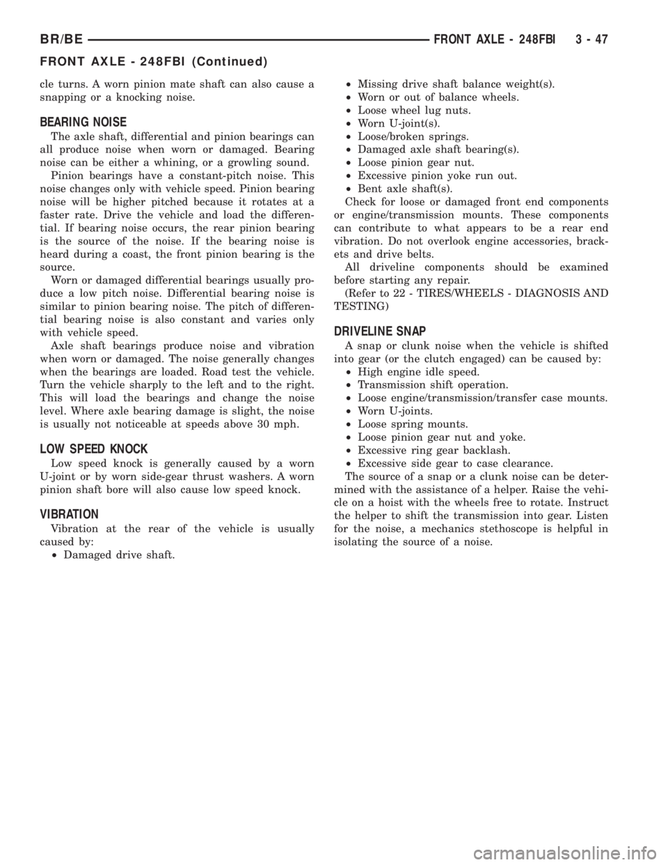
cle turns. A worn pinion mate shaft can also cause a
snapping or a knocking noise.
BEARING NOISE
The axle shaft, differential and pinion bearings can
all produce noise when worn or damaged. Bearing
noise can be either a whining, or a growling sound.
Pinion bearings have a constant-pitch noise. This
noise changes only with vehicle speed. Pinion bearing
noise will be higher pitched because it rotates at a
faster rate. Drive the vehicle and load the differen-
tial. If bearing noise occurs, the rear pinion bearing
is the source of the noise. If the bearing noise is
heard during a coast, the front pinion bearing is the
source.
Worn or damaged differential bearings usually pro-
duce a low pitch noise. Differential bearing noise is
similar to pinion bearing noise. The pitch of differen-
tial bearing noise is also constant and varies only
with vehicle speed.
Axle shaft bearings produce noise and vibration
when worn or damaged. The noise generally changes
when the bearings are loaded. Road test the vehicle.
Turn the vehicle sharply to the left and to the right.
This will load the bearings and change the noise
level. Where axle bearing damage is slight, the noise
is usually not noticeable at speeds above 30 mph.
LOW SPEED KNOCK
Low speed knock is generally caused by a worn
U-joint or by worn side-gear thrust washers. A worn
pinion shaft bore will also cause low speed knock.
VIBRATION
Vibration at the rear of the vehicle is usually
caused by:
²Damaged drive shaft.²Missing drive shaft balance weight(s).
²Worn or out of balance wheels.
²Loose wheel lug nuts.
²Worn U-joint(s).
²Loose/broken springs.
²Damaged axle shaft bearing(s).
²Loose pinion gear nut.
²Excessive pinion yoke run out.
²Bent axle shaft(s).
Check for loose or damaged front end components
or engine/transmission mounts. These components
can contribute to what appears to be a rear end
vibration. Do not overlook engine accessories, brack-
ets and drive belts.
All driveline components should be examined
before starting any repair.
(Refer to 22 - TIRES/WHEELS - DIAGNOSIS AND
TESTING)
DRIVELINE SNAP
A snap or clunk noise when the vehicle is shifted
into gear (or the clutch engaged) can be caused by:
²High engine idle speed.
²Transmission shift operation.
²Loose engine/transmission/transfer case mounts.
²Worn U-joints.
²Loose spring mounts.
²Loose pinion gear nut and yoke.
²Excessive ring gear backlash.
²Excessive side gear to case clearance.
The source of a snap or a clunk noise can be deter-
mined with the assistance of a helper. Raise the vehi-
cle on a hoist with the wheels free to rotate. Instruct
the helper to shift the transmission into gear. Listen
for the noise, a mechanics stethoscope is helpful in
isolating the source of a noise.
BR/BEFRONT AXLE - 248FBI 3 - 47
FRONT AXLE - 248FBI (Continued)
Page 121 of 2889
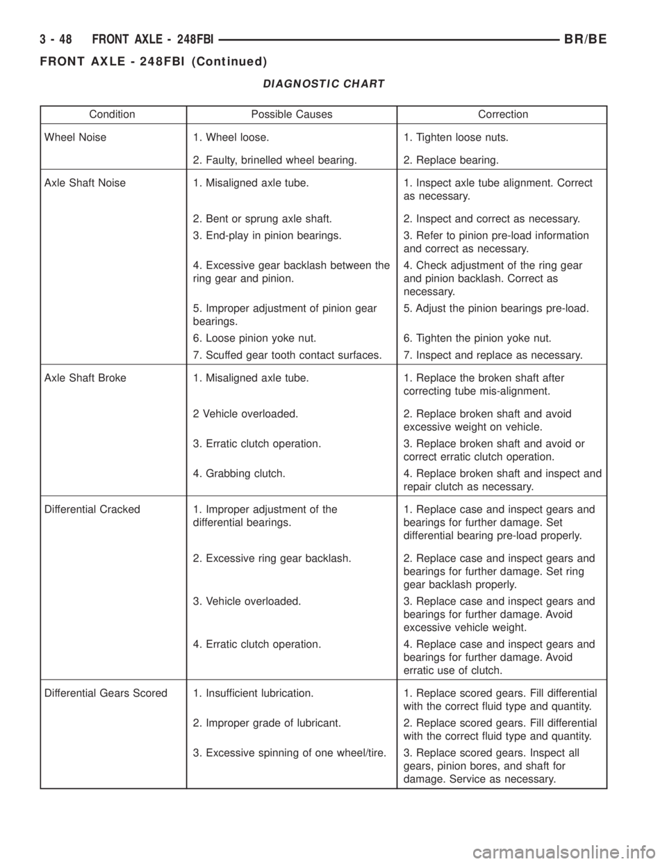
DIAGNOSTIC CHART
Condition Possible Causes Correction
Wheel Noise 1. Wheel loose. 1. Tighten loose nuts.
2. Faulty, brinelled wheel bearing. 2. Replace bearing.
Axle Shaft Noise 1. Misaligned axle tube. 1. Inspect axle tube alignment. Correct
as necessary.
2. Bent or sprung axle shaft. 2. Inspect and correct as necessary.
3. End-play in pinion bearings. 3. Refer to pinion pre-load information
and correct as necessary.
4. Excessive gear backlash between the
ring gear and pinion.4. Check adjustment of the ring gear
and pinion backlash. Correct as
necessary.
5. Improper adjustment of pinion gear
bearings.5. Adjust the pinion bearings pre-load.
6. Loose pinion yoke nut. 6. Tighten the pinion yoke nut.
7. Scuffed gear tooth contact surfaces. 7. Inspect and replace as necessary.
Axle Shaft Broke 1. Misaligned axle tube. 1. Replace the broken shaft after
correcting tube mis-alignment.
2 Vehicle overloaded. 2. Replace broken shaft and avoid
excessive weight on vehicle.
3. Erratic clutch operation. 3. Replace broken shaft and avoid or
correct erratic clutch operation.
4. Grabbing clutch. 4. Replace broken shaft and inspect and
repair clutch as necessary.
Differential Cracked 1. Improper adjustment of the
differential bearings.1. Replace case and inspect gears and
bearings for further damage. Set
differential bearing pre-load properly.
2. Excessive ring gear backlash. 2. Replace case and inspect gears and
bearings for further damage. Set ring
gear backlash properly.
3. Vehicle overloaded. 3. Replace case and inspect gears and
bearings for further damage. Avoid
excessive vehicle weight.
4. Erratic clutch operation. 4. Replace case and inspect gears and
bearings for further damage. Avoid
erratic use of clutch.
Differential Gears Scored 1. Insufficient lubrication. 1. Replace scored gears. Fill differential
with the correct fluid type and quantity.
2. Improper grade of lubricant. 2. Replace scored gears. Fill differential
with the correct fluid type and quantity.
3. Excessive spinning of one wheel/tire. 3. Replace scored gears. Inspect all
gears, pinion bores, and shaft for
damage. Service as necessary.
3 - 48 FRONT AXLE - 248FBIBR/BE
FRONT AXLE - 248FBI (Continued)
Page 122 of 2889
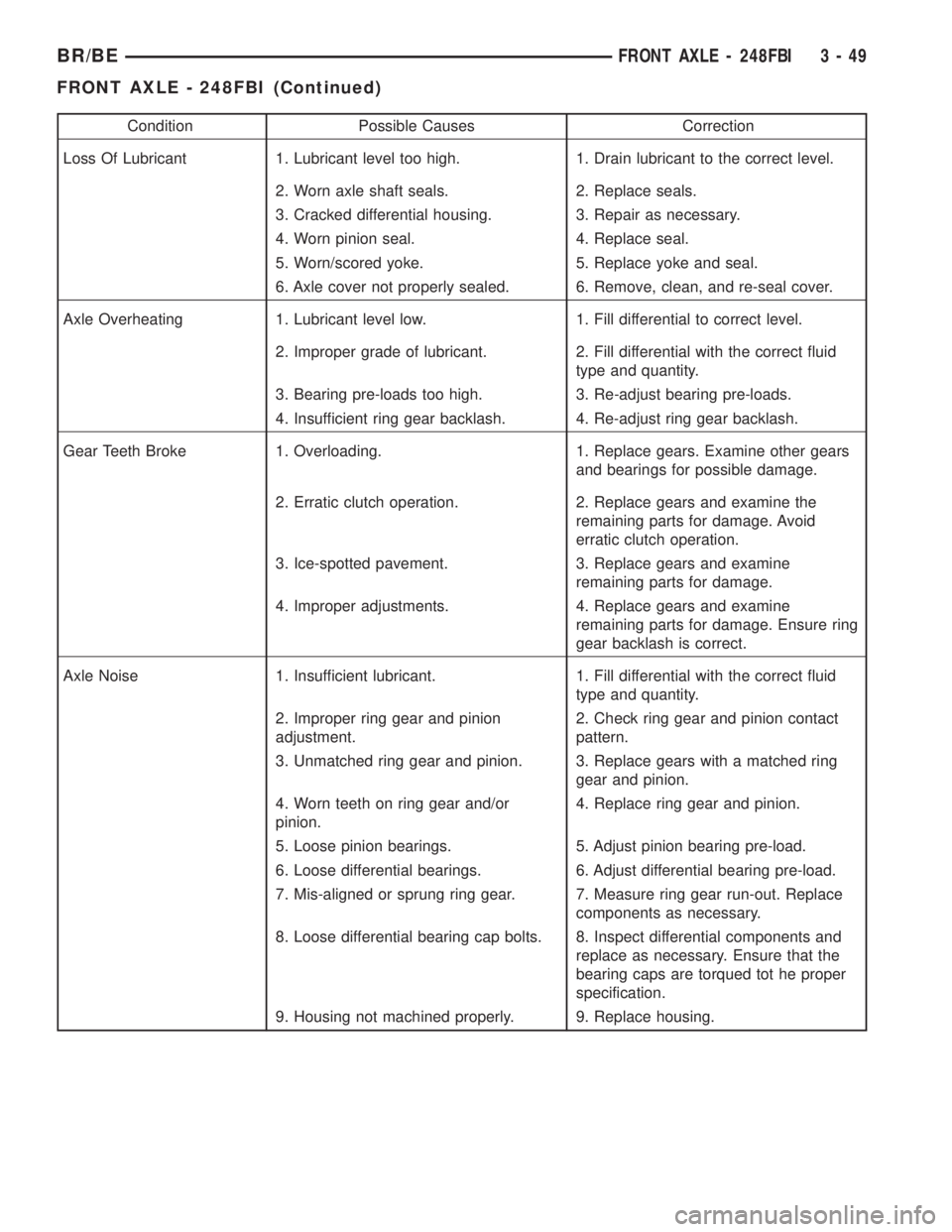
Condition Possible Causes Correction
Loss Of Lubricant 1. Lubricant level too high. 1. Drain lubricant to the correct level.
2. Worn axle shaft seals. 2. Replace seals.
3. Cracked differential housing. 3. Repair as necessary.
4. Worn pinion seal. 4. Replace seal.
5. Worn/scored yoke. 5. Replace yoke and seal.
6. Axle cover not properly sealed. 6. Remove, clean, and re-seal cover.
Axle Overheating 1. Lubricant level low. 1. Fill differential to correct level.
2. Improper grade of lubricant. 2. Fill differential with the correct fluid
type and quantity.
3. Bearing pre-loads too high. 3. Re-adjust bearing pre-loads.
4. Insufficient ring gear backlash. 4. Re-adjust ring gear backlash.
Gear Teeth Broke 1. Overloading. 1. Replace gears. Examine other gears
and bearings for possible damage.
2. Erratic clutch operation. 2. Replace gears and examine the
remaining parts for damage. Avoid
erratic clutch operation.
3. Ice-spotted pavement. 3. Replace gears and examine
remaining parts for damage.
4. Improper adjustments. 4. Replace gears and examine
remaining parts for damage. Ensure ring
gear backlash is correct.
Axle Noise 1. Insufficient lubricant. 1. Fill differential with the correct fluid
type and quantity.
2. Improper ring gear and pinion
adjustment.2. Check ring gear and pinion contact
pattern.
3. Unmatched ring gear and pinion. 3. Replace gears with a matched ring
gear and pinion.
4. Worn teeth on ring gear and/or
pinion.4. Replace ring gear and pinion.
5. Loose pinion bearings. 5. Adjust pinion bearing pre-load.
6. Loose differential bearings. 6. Adjust differential bearing pre-load.
7. Mis-aligned or sprung ring gear. 7. Measure ring gear run-out. Replace
components as necessary.
8. Loose differential bearing cap bolts. 8. Inspect differential components and
replace as necessary. Ensure that the
bearing caps are torqued tot he proper
specification.
9. Housing not machined properly. 9. Replace housing.
BR/BEFRONT AXLE - 248FBI 3 - 49
FRONT AXLE - 248FBI (Continued)
Page 150 of 2889
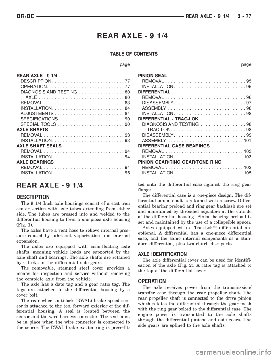
REAR AXLE-91/4
TABLE OF CONTENTS
page page
REAR AXLE-91/4
DESCRIPTION...........................77
OPERATION.............................77
DIAGNOSIS AND TESTING.................80
AXLE................................80
REMOVAL..............................83
INSTALLATION...........................84
ADJUSTMENTS..........................84
SPECIFICATIONS........................90
SPECIAL TOOLS.........................90
AXLE SHAFTS
REMOVAL..............................93
INSTALLATION...........................93
AXLE SHAFT SEALS
REMOVAL..............................94
INSTALLATION...........................94
AXLE BEARINGS
REMOVAL..............................94
INSTALLATION...........................95PINION SEAL
REMOVAL..............................95
INSTALLATION...........................95
DIFFERENTIAL
REMOVAL..............................96
DISASSEMBLY...........................97
ASSEMBLY.............................98
INSTALLATION...........................98
DIFFERENTIAL - TRAC-LOK
DIAGNOSIS AND TESTING.................98
TRAC-LOK............................98
DISASSEMBLY...........................99
ASSEMBLY............................101
DIFFERENTIAL CASE BEARINGS
REMOVAL.............................103
INSTALLATION..........................103
PINION GEAR/RING GEAR/TONE RING
REMOVAL.............................103
INSTALLATION..........................105
REAR AXLE-91/4
DESCRIPTION
The 9 1/4 Inch axle housings consist of a cast iron
center section with axle tubes extending from either
side. The tubes are pressed into and welded to the
differential housing to form a one-piece axle housing
(Fig. 1).
The axles have a vent hose to relieve internal pres-
sure caused by lubricant vaporization and internal
expansion.
The axles are equipped with semi-floating axle
shafts, meaning vehicle loads are supported by the
axle shaft and bearings. The axle shafts are retained
by C-locks in the differential side gears.
The removable, stamped steel cover provides a
means for inspection and service without removing
the complete axle from the vehicle.
The axle has a date tag and a gear ratio tag. The
tags are attached to the differential housing by a
cover bolt.
The rear wheel anti-lock (RWAL) brake speed sen-
sor is attached to the top, forward exterior of the dif-
ferential housing. A seal is located between the
sensor and the wire harness connector. The seal must
be in place when the wire connector is connected to
the sensor. The RWAL brake exciter ring is press-fit-ted onto the differential case against the ring gear
flange.
The differential case is a one-piece design. The dif-
ferential pinion shaft is retained with a screw. Differ-
ential bearing preload and ring gear backlash are set
and maintained by threaded adjusters at the outside
of the differential housing. Pinion bearing preload is
set and maintained by the use of a collapsible spacer.
Axles equipped with a Trac-Lokydifferential are
optional. A differential has a one-piece differential
case, and the same internal components as a stan-
dard differential, plus two clutch disc packs.
AXLE IDENTIFICATION
The axle differential cover can be used for identifi-
cation of the axle (Fig. 2). A ratio tag is attached to
the top of the differential cover.
OPERATION
The axle receives power from the transmission/
transfer case through the rear propeller shaft. The
rear propeller shaft is connected to the drive pinion
which rotates the differential through the gear mesh
with the ring gear bolted to the differential case. The
engine power is transmitted to the axle shafts
through the differential pinions and side gears. The
side gears are splined to the axle shafts.
BR/BEREAR AXLE - 9 1/4 3 - 77