2001 DODGE RAM service indicator
[x] Cancel search: service indicatorPage 15 of 2889

It is even more important to look for gasoline with-
out MMT in Canada because MMT can be used at
levels higher than allowed in the United States.
MMT is prohibited in Federal and California refor-
mulated gasoline.
SULFUR IN GASOLINE
If you live in the northeast United States, your
vehicle may have been designed to meet California
low emission standards with Cleaner-Burning Cali-
fornia reformulated gasoline with low sulfur. If such
fuels are not available in states adopting California
emission standards, your vehicles will operate satis-
factorily on fuels meeting federal specifications, but
emission control system performance may be
adversely affected. Gasoline sold outside of California
is permitted to have higher sulfur levels which may
affect the performance of the vehicle's catalytic con-
verter. This may cause the Malfunction Indicator
Lamp (MIL), Check Engine or Service Engine Soon
light to illuminate. We recommend that you try a dif-
ferent brand of unleaded gasoline having lower sulfur
to determine if the problem is fuel related prior to
returning your vehicle to an authorized dealer for
service.
CAUTION: If the Malfunction Indicator Lamp (MIL),
Check Engine or Service Engine Soon light is flash-
ing, immediate service is required; see on-board
diagnostics system section.
MATERIALS ADDED TO FUEL
All gasoline sold in the United States and Canada
are required to contain effective detergent additives.
Use of additional detergents or other additives is not
needed under normal conditions.
FUEL SYSTEM CAUTIONS
CAUTION: Follow these guidelines to maintain your
vehicle's performance:
²The use of leaded gas is prohibited by Federal
law. Using leaded gasoline can impair engine perfor-
mance, damage the emission control system, and
could result in loss of warranty coverage.
²An out-of-tune engine, or certain fuel or ignition
malfunctions, can cause the catalytic converter to
overheat. If you notice a pungent burning odor or
some light smoke, your engine may be out of tune or
malfunctioning and may require immediate service.
Contact your dealer for service assistance.²When pulling a heavy load or driving a fully
loaded vehicle when the humidity is low and the tem-
perature is high, use a premium unleaded fuel to
help prevent spark knock. If spark knock persists,
lighten the load, or engine piston damage may result.
²The use of fuel additives which are now being
sold as octane enhancers is not recommended. Most
of these products contain high concentrations of
methanol. Fuel system damage or vehicle perfor-
mance problems resulting from the use of such fuels
or additives is not the responsibility of Daimler-
Chrysler Corporation and may not be covered under
the new vehicle warranty.
NOTE: Intentional tampering with emissions control
systems can result in civil penalties being assessed
against you.
DESCRIPTION - FUEL REQUIREMENTS -
DIESEL ENGINE
DESCRIPTION
WARNING: Do not use alcohol or gasoline as a fuel
blending agent. They can be unstable under certain
conditions and hazardous or explosive when mixed
with diesel fuel.
Use good quality diesel fuel from a reputable sup-
plier in your Dodge truck. For most year-round ser-
vice, number 2 diesel fuel meeting ASTM
specification D-975 will provide good performance. If
the vehicle is exposed to extreme cold (below 0ÉF/-
18ÉC), or is required to operate at colder-than-normal
conditions for prolonged periods, use climatized No. 2
diesel fuel or dilute the No. 2 diesel fuel with 50%
No. 1 diesel fuel. This will provide better protection
from fuel gelling or wax-plugging of the fuel filters.
Diesel fuel is seldom completely free of water. To
prevent fuel system trouble, including fuel line freez-
ing in winter, drain the accumulated water from the
fuel/water separator using the fuel/water separator
drain provided. If you buy good-quality fuel and fol-
low the cold-weather advice above, fuel conditioners
should not be required in your vehicle. If available in
your area, a high cetane ªpremiumº diesel fuel may
offer improved cold starting and warm-up perfor-
mance.
0 - 2 LUBRICATION & MAINTENANCEBR/BE
LUBRICATION & MAINTENANCE (Continued)
Page 18 of 2889
DESCRIPTION
A multi-purpose, hypoid gear lubricant which con-
forms to the following specifications should be used.
Mopar Hypoid Gear Lubricant conforms to all of
these specifications.
SAE ratings also apply to multiple grade gear
lubricants. In addition, API classification defines the
lubricants usage.
FRONT AXLE
²The lubricant should have MIL-L-2105C and
API GL 5 quality specifications.
²Lubricant is SAE 75W-140 SYNTHETIC gear
lubricant.
REAR AXLE
²The lubricant should have MIL-L-2105C and
API GL 5 quality specifications.
²Lubricant is a thermally stable SAE 80W-90
gear lubricant.
²Lubricant for axles intended for heavy-duty or
trailer tow use is SAE 75W-140 SYNTHETIC gear
lubricant.
NOTE: Trac-lokYand Vari-lokYequipped axles
require a friction modifier be added to the lubricant.
CAUTION: If axle is submerged in water, lubricant
must be replaced immediately to avoid possible
premature axle failure.
DESCRIPTION - TRANSFER CASE FLUID
Recommended lubricant for the NV231 and NV241
transfer case is MopartATF +4, (MS 9602) Auto-
matic Transmission Fluid.
DESCRIPTION - AUTOMATIC TRANSMISSION
FLUID
NOTE: Refer to the maintenance schedules in this
group for the recommended maintenance (fluid/filter
change) intervals for this transmission.
NOTE: Refer to Service Procedures in this group for
fluid level checking procedures.
MopartATF +4, type 9602, Automatic Transmis-
sion Fluid is the recommended fluid for Daimler-
Chrysler automatic transmissions.
Dexron II fluid IS NOT recommended. Clutch
chatter can result from the use of improper
fluid.MopartATF +4, type 9602, Automatic Transmis-
sion Fluid when new is red in color. The ATF is dyed
red so it can be identified from other fluids used in
the vehicle such as engine oil or antifreeze. The red
color is not permanent and is not an indicator of fluid
condition. As the vehicle is driven, the ATF will begin
to look darker in color and may eventually become
brown.This is normal.A dark brown/black fluid
accompanied with a burnt odor and/or deterioration
in shift quality may indicate fluid deterioration or
transmission component failure.
FLUID ADDITIVES
DaimlerChrysler strongly recommends against the
addition of any fluids to the transmission, other than
those automatic transmission fluids listed above.
Exceptions to this policy are the use of special dyes
to aid in detecting fluid leaks.
Various ªspecialº additives and supplements exist
that claim to improve shift feel and/or quality. These
additives and others also claim to improve converter
clutch operation and inhibit overheating, oxidation,
varnish, and sludge. These claims have not been sup-
ported to the satisfaction of DaimlerChrysler and
these additivesmust not be used.The use of trans-
mission ªsealersº should also be avoided, since they
may adversely affect the integrity of transmission
seals.
OPERATION - AUTOMATIC TRANSMISSION
FLUID
The automatic transmission fluid is selected based
upon several qualities. The fluid must provide a high
level of protection for the internal components by
providing a lubricating film between adjacent metal
components. The fluid must also be thermally stable
so that it can maintain a consistent viscosity through
a large temperature range. If the viscosity stays con-
stant through the temperature range of operation,
transmission operation and shift feel will remain con-
sistent. Transmission fluid must also be a good con-
ductor of heat. The fluid must absorb heat from the
internal transmission components and transfer that
heat to the transmission case.
BR/BELUBRICATION & MAINTENANCE 0 - 5
FLUID TYPES (Continued)
Page 32 of 2889
²Flush and replace engine coolant if it has been
30,000 miles (48 000 km) or 24 months since last
change.
²Inspect front wheel bearings. Clean and repack,
if required (4x4).
²Inspect engine air cleaner element, replace
as necessary (8.0L only).
*Requires Service Reminder Indicator Light. If so
equipped, these parts are to be replaced at the indi-
cated mileage or when the service reminder indicator
light remains on continuously with the key in the
ªONº position, whichever occurs first.
HEAVY DUTY SCHEDULE ªBº
Follow this schedule if the vehicle is usually oper-
ated under one or more of the following conditions.
²Frequent short trips driving less than 5 miles
(8km)
²Frequent driving in dusty conditions
²Frequent trailer towing
²Extensive idling
²More than 50% of the driving is at sustained
high speeds during hot weather, above 90ÉF (32ÉC)
3,000 Miles (5 000 km)
²Change engine oil.
²Replace engine oil filter.
²Lubricate tie rod ends every 3,000 miles (5 000
km).
6,000 Miles (10 000 km)
²Change engine oil.
²Replace engine oil filter.
²Lubricate tie rod ends every 3,000 miles (5 000
km).
²Inspect front wheel bearings (4x4).
9,000 Miles (14 000 km)
²Change engine oil.
²Replace engine oil filter.
²Lubricate tie rod ends every 3,000 miles (5 000
km).
²Inspect front wheel bearings (4x2).
12,000 Miles (19 000 km)
²Change engine oil.
²Replace engine oil filter.
²Inspect engine air cleaner element and air
pump filter, replace as necessary.
²Drain and refill automatic transmission fluid.
Replace filter and adjust bands.³
²Change rear axle fluid.
²Change front axle fluid (4x4).
²Inspect brake linings.
²Lubricate tie rod ends every 3,000 miles (5 000
km).
²Inspect front wheel bearings (4x4).
15,000 Miles (24 000 km)
²Change engine oil.
²Replace engine oil filter.
²Lubricate tie rod ends every 3,000 miles (5 000
km).
18,000 Miles (29 000 km)
²Change engine oil.
²Replace engine oil filter.
²Lubricate tie rod ends every 3,000 miles (5 000
km).
²Inspect front wheel bearings (4x4).
²Inspect front wheel bearings (4x2).
²Drain and refill transfer case fluid every 18,000
miles (4x4).
21,000 Miles (34 000 km)
²Change engine oil.
²Replace engine oil filter.
²Lubricate tie rod ends every 3,000 miles (5 000
km).
24,000 Miles (38 000 km)
²Change engine oil
²Replace engine oil filter.
²Replace engine air cleaner element and air
pump filter.
²Drain and refill automatic transmission fluid.
Replace filter and adjust bands.
²Change rear axle fluid.
²Change front axle fluid (4x4).
²Clean and lubricate crankcase inlet air filter
(5.9L).
²Inspect front wheel bearings. Clean and repack,
if required (4x2).
²Inspect brake linings.
²Lubricate tie rod ends every 3,000 miles (5 000
km).
²Inspect front wheel bearings (4x4).
27,000 Miles (43 000 km)
²Change engine oil.
²Replace engine oil filter.
²Lubricate tie rod ends every 3,000 miles (5 000
km).
²Inspect front wheel bearings (4x2).
30,000 Miles (48 000 km)
²Change engine oil.
²Replace engine oil filter.
²Lubricate tie rod ends every 3,000 miles (5 000
km).
²Inspect PCV valve, replace as necessary
(5.9L).
²Replace spark plugs.
²Inspect front wheel bearings (4x4).
BR/BELUBRICATION & MAINTENANCE 0 - 19
MAINTENANCE SCHEDULES (Continued)
Page 35 of 2889
99,000 Miles (156 000 km)
²Change engine oil.
²Replace engine oil filter.
²Lubricate tie rod ends every 3,000 miles (5 000
km).
²Inspect front wheel bearings (4x2).
102,000 Miles (163 000 km)
²Change engine oil.
²Replace engine oil filter.
²Lubricate tie rod ends every 3,000 miles (5 000
km).
²Inspect front wheel bearings (4x4).
105,000 Miles (168 000 km)
²Change engine oil.
²Replace engine oil filter.
²Lubricate tie rod ends every 3,000 miles (5 000
km).
108,000 Miles (173 000 km)
²Change engine oil.
²Replace engine oil filter.
²Inspect engine air cleaner element and air
pump filter, replace as necessary.
²Drain and refill automatic transmission fluid.
Replace filter and adjust bands.³
²Drain and refill transfer case fluid (4x4).
²Change rear axle fluid.
²Change front axle fluid (4x4).
²Inspect brake linings.
²Flush and replace engine coolant if it has been
30,000 miles (48 000 km) since last change.
²Lubricate tie rod ends every 3,000 miles (5 000
km).
²Inspect front wheel bearings (4x4).
²Inspect front wheel bearings (4x2).
*Requires Service Reminder Indicator Light. If so
equipped, these parts are to be replaced at the indi-
cated mileage or when the service reminder indicator
light remains on continuously with the key in the
ªONº position, whichever occurs first.
³Off-the-highway operation, trailer towing, snow
plowing, prolonged operation with heavy loading,
especially in hot weather require the more frequent
transmission service indicated witha³inSchedule
ªBº. Perform these services if you usually operate
your Ram Truck under these conditions.
Inspection and service should also be performed
anytime a malfunction is observed or suspected.
DESCRIPTION - MAINTENANCE SCHEDULES
Ð 24±VALVE CUMMINS TURBO DIESEL
There are two maintenance schedules that show
proper service for the vehicle.First is ScheduleªA.ºIt lists all the scheduled
maintenance to be performed under ªnormalº operat-
ing conditions.
Second is ScheduleªB.ºIt is a schedule for vehicles
that are operated under the conditions listed at the
beginning of that schedule.
Use the schedule that best describes the driving
conditions.
Where time and mileage are listed, follow the
interval that occurs first.
At Each Stop For Fuel
²Check engine oil level and add as required.
²Check windshield washer solvent and add if
required.
²Clean windshield and wiper blades as required.
²Drain water from fuel filter.
Once A Month
²Check tire pressure and look for unusual wear
or damage.
²Inspect battery and clean and tighten terminals
as required.
²Check fluid levels of coolant reservoir, brake
master cylinder, power steering, and transmission.
Add fluid as required.
²Check all lights and all other electrical items for
correct operation.
²Check Filter Mindery. Replace air cleaner
element if necessary.
²Inspect and clean wiper blades. Replace if
required.
At Each Oil Change
²Inspect exhaust system.
²Inspect brake hoses.
²Adjust rear brakes.
²Rotate the tires at each oil change interval
shown at 7, 5000 miles (12 000 km) on schedule ªAº
or every other interval shown at 7,500 miles (12 000
km) on schedule ªBº.
²Check engine coolant level, hoses, and clamps.
²Lubricate steering linkage.
²Drain crankcase breather canister (if equipped).
EMISSION CONTROL SYSTEM MAINTENANCE
The scheduled emission maintenance listed inbold
typeon the Maintenance Schedules, must be done at
the mileage specified to assure the continued proper
functioning of the emission control system. These,
and all other maintenance services included in this
manual, should be done to provide the best vehicle
performance and reliability. More frequent mainte-
nance may be needed for vehicles in severe operating
conditions such as dusty areas and very short trip
driving.
0 - 22 LUBRICATION & MAINTENANCEBR/BE
MAINTENANCE SCHEDULES (Continued)
Page 92 of 2889
NOTE: Arbor Discs 6732 has different step diame-
ters to fit other axles. Choose proper step for axle
being serviced.(5) Install differential bearing caps on arbor discs
and snug the bearing cap bolts. Then cross tighten
cap bolts to 108 N´m (80 ft. lbs.).
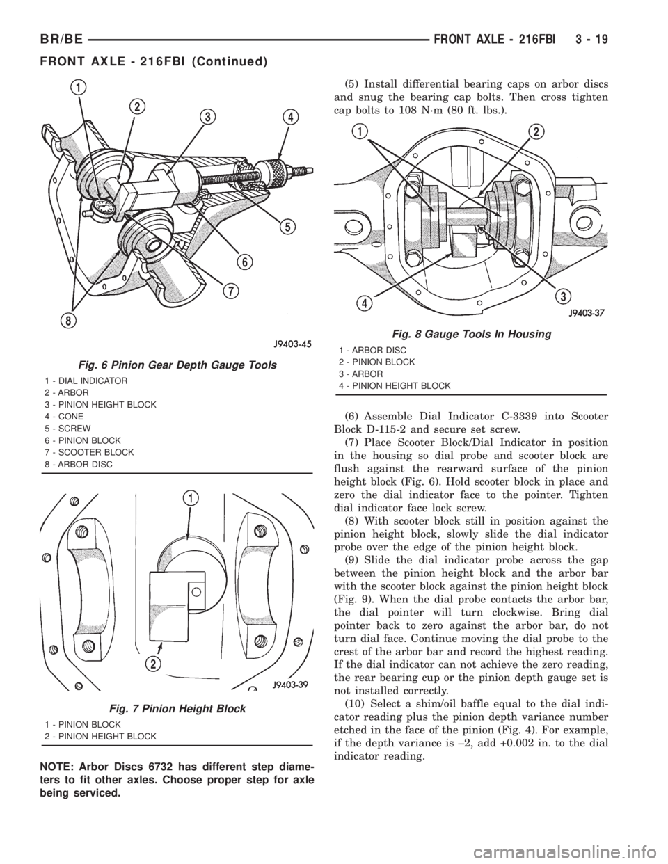
(6) Assemble Dial Indicator C-3339 into Scooter
Block D-115-2 and secure set screw.
(7) Place Scooter Block/Dial Indicator in position
in the housing so dial probe and scooter block are
flush against the rearward surface of the pinion
height block (Fig. 6). Hold scooter block in place and
zero the dial indicator face to the pointer. Tighten
dial indicator face lock screw.
(8) With scooter block still in position against the
pinion height block, slowly slide the dial indicator
probe over the edge of the pinion height block.
(9) Slide the dial indicator probe across the gap
between the pinion height block and the arbor bar
with the scooter block against the pinion height block
(Fig. 9). When the dial probe contacts the arbor bar,
the dial pointer will turn clockwise. Bring dial
pointer back to zero against the arbor bar, do not
turn dial face. Continue moving the dial probe to the
crest of the arbor bar and record the highest reading.
If the dial indicator can not achieve the zero reading,
the rear bearing cup or the pinion depth gauge set is
not installed correctly.
(10) Select a shim/oil baffle equal to the dial indi-
cator reading plus the pinion depth variance number
etched in the face of the pinion (Fig. 4). For example,
if the depth variance is ±2, add +0.002 in. to the dial
indicator reading.
Fig. 6 Pinion Gear Depth Gauge Tools
1 - DIAL INDICATOR
2 - ARBOR
3 - PINION HEIGHT BLOCK
4 - CONE
5 - SCREW
6 - PINION BLOCK
7 - SCOOTER BLOCK
8 - ARBOR DISC
Fig. 7 Pinion Height Block
1 - PINION BLOCK
2 - PINION HEIGHT BLOCK
Fig. 8 Gauge Tools In Housing
1 - ARBOR DISC
2 - PINION BLOCK
3 - ARBOR
4 - PINION HEIGHT BLOCK
BR/BEFRONT AXLE - 216FBI 3 - 19
FRONT AXLE - 216FBI (Continued)
Page 106 of 2889
REMOVAL
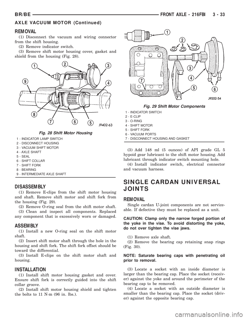
(1) Disconnect the vacuum and wiring connector
from the shift housing.
(2) Remove indicator switch.
(3) Remove shift motor housing cover, gasket and
shield from the housing (Fig. 28).
DISASSEMBLY
(1) Remove E-clips from the shift motor housing
and shaft. Remove shift motor and shift fork from
the housing (Fig. 29).
(2) Remove O-ring seal from the shift motor shaft.
(3) Clean and inspect all components. Replaced
any component that is excessively worn or damaged.
ASSEMBLY
(1) Install a new O-ring seal on the shift motor
shaft.
(2) Insert shift motor shaft through the hole in the
housing and shift fork. The shift fork offset should be
toward the differential.
(3) Install E-clips on the shift motor shaft and
housing.
INSTALLATION
(1) Install shift motor housing gasket and cover.
Ensure shift fork is correctly guided into the shift
collar groove.
(2) Install shift motor housing shield and tighten
the bolts to 11 N´m (96 in. lbs.).(3) Add 148 ml (5 ounces) of API grade GL 5
hypoid gear lubricant to the shift motor housing. Add
lubricant through indicator switch mounting hole.
(4) Install indicator switch, electrical connector
and vacuum harness.
SINGLE CARDAN UNIVERSAL
JOINTS
REMOVAL
Single cardan U-joint components are not service-
able. If defective they must be replaced as a unit.
CAUTION: Clamp only the narrow forged portion of
the yoke in the vise. To avoid distorting the yoke,
do not over tighten the vise jaws.
(1) Remove axle shaft.
(2) Remove the bearing cap retaining snap rings
(Fig. 30).
NOTE: Saturate bearing caps with penetrating oil
prior to removal.
(3) Locate a socket with an inside diameter is
larger than the bearing cap. Place the socket (receiv-
er) against the yoke and around the perimeter of the
bearing cap to be removed.
(4) Locate a socket with an outside diameter is
smaller than the bearing cap. Place the socket (driv-
er) against the opposite bearing cap.
Fig. 28 Shift Motor Housing
1 - INDICATOR LAMP SWITCH
2 - DISCONNECT HOUSING
3 - VACUUM SHIFT MOTOR
4 - AXLE SHAFT
5 - SEAL
6 - SHIFT COLLAR
7 - SHIFT FORK
8 - BEARING
9 - INTERMEDIATE AXLE SHAFT
Fig. 29 Shift Motor Components
1 - INDICATOR SWITCH
2 - E-CLIP
3 - O-RING
4 - SHIFT MOTOR
5 - SHIFT FORK
6 - VACUUM PORTS
7 - DISCONNECT HOUSING AND GASKET
BR/BEFRONT AXLE - 216FBI 3 - 33
AXLE VACUUM MOTOR (Continued)
Page 125 of 2889
NOTE: Arbor Discs 6732 has different step diame-
ters to fit other axles. Choose proper step for axle
being serviced.(5) Install differential bearing caps on arbor discs
and snug the bearing cap bolts. Then cross tighten
cap bolts to 108 N´m (80 ft. lbs.).
(6) Assemble Dial Indicator C-3339 into Scooter
Block D-115-2 and secure set screw.
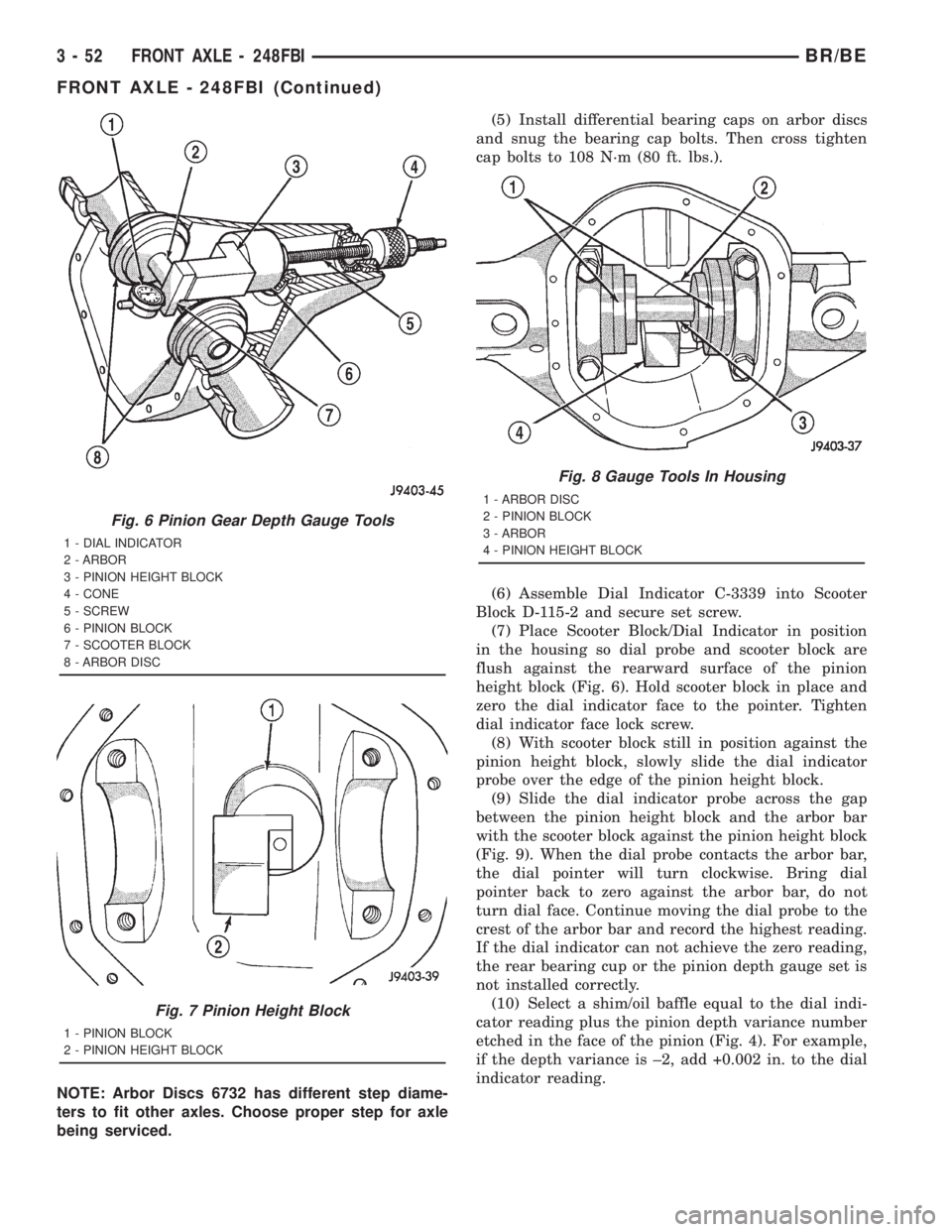
(7) Place Scooter Block/Dial Indicator in position
in the housing so dial probe and scooter block are
flush against the rearward surface of the pinion
height block (Fig. 6). Hold scooter block in place and
zero the dial indicator face to the pointer. Tighten
dial indicator face lock screw.
(8) With scooter block still in position against the
pinion height block, slowly slide the dial indicator
probe over the edge of the pinion height block.
(9) Slide the dial indicator probe across the gap
between the pinion height block and the arbor bar
with the scooter block against the pinion height block
(Fig. 9). When the dial probe contacts the arbor bar,
the dial pointer will turn clockwise. Bring dial
pointer back to zero against the arbor bar, do not
turn dial face. Continue moving the dial probe to the
crest of the arbor bar and record the highest reading.
If the dial indicator can not achieve the zero reading,
the rear bearing cup or the pinion depth gauge set is
not installed correctly.
(10) Select a shim/oil baffle equal to the dial indi-
cator reading plus the pinion depth variance number
etched in the face of the pinion (Fig. 4). For example,
if the depth variance is ±2, add +0.002 in. to the dial
indicator reading.
Fig. 6 Pinion Gear Depth Gauge Tools
1 - DIAL INDICATOR
2 - ARBOR
3 - PINION HEIGHT BLOCK
4 - CONE
5 - SCREW
6 - PINION BLOCK
7 - SCOOTER BLOCK
8 - ARBOR DISC
Fig. 7 Pinion Height Block
1 - PINION BLOCK
2 - PINION HEIGHT BLOCK
Fig. 8 Gauge Tools In Housing
1 - ARBOR DISC
2 - PINION BLOCK
3 - ARBOR
4 - PINION HEIGHT BLOCK
3 - 52 FRONT AXLE - 248FBIBR/BE
FRONT AXLE - 248FBI (Continued)
Page 138 of 2889
REMOVAL
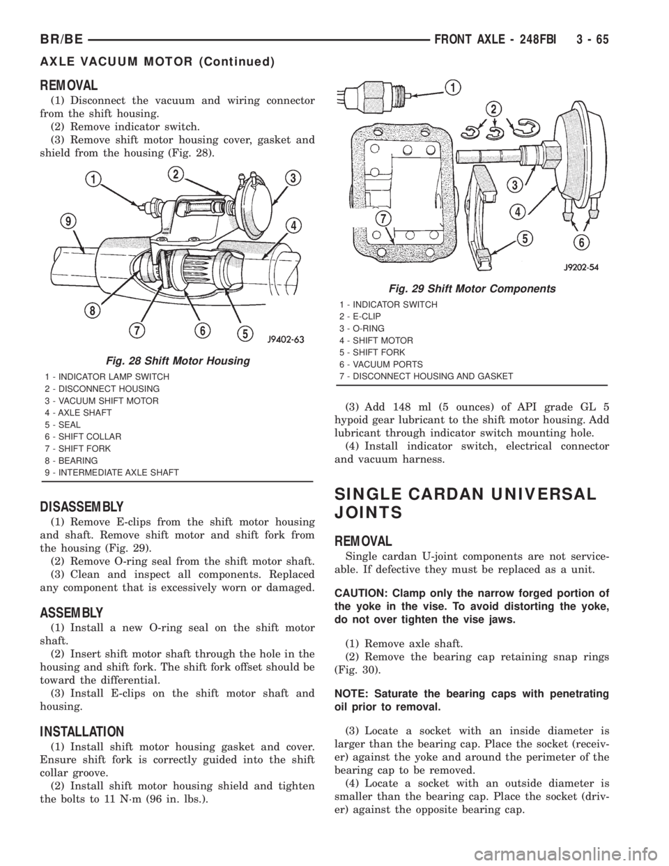
(1) Disconnect the vacuum and wiring connector
from the shift housing.
(2) Remove indicator switch.
(3) Remove shift motor housing cover, gasket and
shield from the housing (Fig. 28).
DISASSEMBLY
(1) Remove E-clips from the shift motor housing
and shaft. Remove shift motor and shift fork from
the housing (Fig. 29).
(2) Remove O-ring seal from the shift motor shaft.
(3) Clean and inspect all components. Replaced
any component that is excessively worn or damaged.
ASSEMBLY
(1) Install a new O-ring seal on the shift motor
shaft.
(2) Insert shift motor shaft through the hole in the
housing and shift fork. The shift fork offset should be
toward the differential.
(3) Install E-clips on the shift motor shaft and
housing.
INSTALLATION
(1) Install shift motor housing gasket and cover.
Ensure shift fork is correctly guided into the shift
collar groove.
(2) Install shift motor housing shield and tighten
the bolts to 11 N´m (96 in. lbs.).(3) Add 148 ml (5 ounces) of API grade GL 5
hypoid gear lubricant to the shift motor housing. Add
lubricant through indicator switch mounting hole.
(4) Install indicator switch, electrical connector
and vacuum harness.
SINGLE CARDAN UNIVERSAL
JOINTS
REMOVAL
Single cardan U-joint components are not service-
able. If defective they must be replaced as a unit.
CAUTION: Clamp only the narrow forged portion of
the yoke in the vise. To avoid distorting the yoke,
do not over tighten the vise jaws.
(1) Remove axle shaft.
(2) Remove the bearing cap retaining snap rings
(Fig. 30).
NOTE: Saturate the bearing caps with penetrating
oil prior to removal.
(3) Locate a socket with an inside diameter is
larger than the bearing cap. Place the socket (receiv-
er) against the yoke and around the perimeter of the
bearing cap to be removed.
(4) Locate a socket with an outside diameter is
smaller than the bearing cap. Place the socket (driv-
er) against the opposite bearing cap.
Fig. 28 Shift Motor Housing
1 - INDICATOR LAMP SWITCH
2 - DISCONNECT HOUSING
3 - VACUUM SHIFT MOTOR
4 - AXLE SHAFT
5 - SEAL
6 - SHIFT COLLAR
7 - SHIFT FORK
8 - BEARING
9 - INTERMEDIATE AXLE SHAFT
Fig. 29 Shift Motor Components
1 - INDICATOR SWITCH
2 - E-CLIP
3 - O-RING
4 - SHIFT MOTOR
5 - SHIFT FORK
6 - VACUUM PORTS
7 - DISCONNECT HOUSING AND GASKET
BR/BEFRONT AXLE - 248FBI 3 - 65
AXLE VACUUM MOTOR (Continued)