2001 DODGE RAM service indicator
[x] Cancel search: service indicatorPage 158 of 2889
PINION GEAR DEPTH VARIANCE
Original Pinion
Gear Depth
VarianceReplacement Pinion Gear Depth Variance
þ4 þ3 þ2 þ1 0 +1 +2 +3 +4
+4+0.008 +0.007 +0.006 +0.005 +0.004 +0.003 +0.002 +0.001 0
+3+0.007 +0.006 +0.005 +0.004 +0.003 +0.002 +0.001 0 þ0.001
+2+0.006 +0.005 +0.004 +0.003 +0.002 +0.001 0 þ0.001 þ0.002
+1+0.005 +0.004 +0.003 +0.002 +0.001 0 þ0.001 þ0.002 þ0.003
0+0.004 +0.003 +0.002 +0.001 0 þ0.001 þ0.002 þ0.003 þ0.004
þ1+0.003 +0.002 +0.001 0 þ0.001 þ0.002 þ0.003 þ0.004 þ0.005
þ2+0.002 +0.001 0 þ0.001 þ0.002 þ0.003 þ0.004 þ0.005 þ0.006
þ3+0.001 0 þ0.001 þ0.002 þ0.003 þ0.004 þ0.005 þ0.006 þ0.007
þ40 þ0.001 þ0.002 þ0.003 þ0.004 þ0.005 þ0.006 þ0.007 þ0.008
PINION DEPTH MEASUREMENT
Measurements are taken with pinion bearing cups
and pinion bearings installed in the housing. Take
measurements with Pinion Gauge Set and Dial Indi-
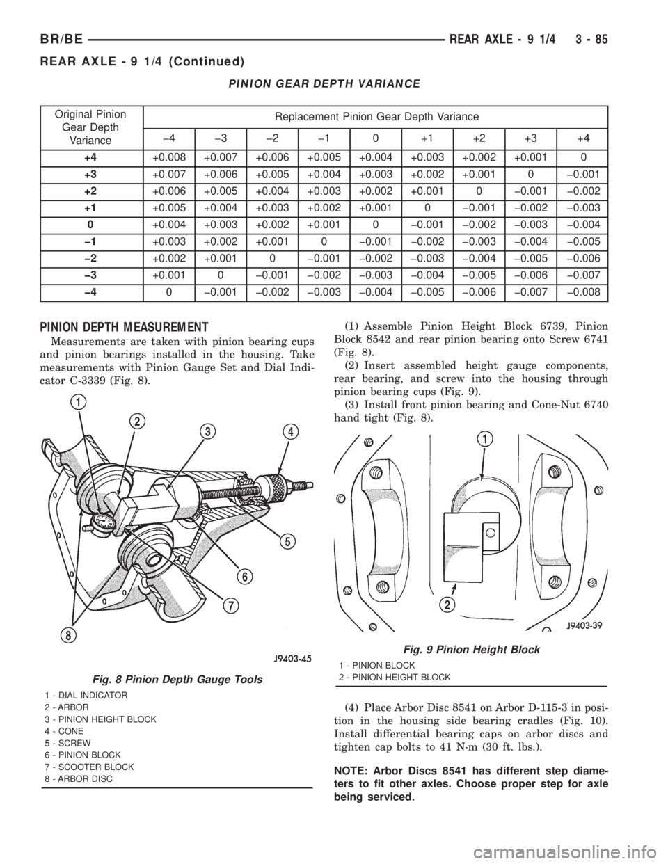
cator C-3339 (Fig. 8).(1) Assemble Pinion Height Block 6739, Pinion
Block 8542 and rear pinion bearing onto Screw 6741
(Fig. 8).
(2) Insert assembled height gauge components,
rear bearing, and screw into the housing through
pinion bearing cups (Fig. 9).
(3) Install front pinion bearing and Cone-Nut 6740
hand tight (Fig. 8).
(4) Place Arbor Disc 8541 on Arbor D-115-3 in posi-
tion in the housing side bearing cradles (Fig. 10).
Install differential bearing caps on arbor discs and
tighten cap bolts to 41 N´m (30 ft. lbs.).
NOTE: Arbor Discs 8541 has different step diame-
ters to fit other axles. Choose proper step for axle
being serviced.
Fig. 8 Pinion Depth Gauge Tools
1 - DIAL INDICATOR
2 - ARBOR
3 - PINION HEIGHT BLOCK
4 - CONE
5 - SCREW
6 - PINION BLOCK
7 - SCOOTER BLOCK
8 - ARBOR DISC
Fig. 9 Pinion Height Block
1 - PINION BLOCK
2 - PINION HEIGHT BLOCK
BR/BEREAR AXLE - 9 1/4 3 - 85
REAR AXLE - 9 1/4 (Continued)
Page 188 of 2889
PINION GEAR DEPTH VARIANCE
Original Pinion
Gear Depth
VarianceReplacement Pinion Gear Depth Variance
þ4 þ3 þ2 þ1 0 +1 +2 +3 +4
+4+0.008 +0.007 +0.006 +0.005 +0.004 +0.003 +0.002 +0.001 0
+3+0.007 +0.006 +0.005 +0.004 +0.003 +0.002 +0.001 0 þ0.001
+2+0.006 +0.005 +0.004 +0.003 +0.002 +0.001 0 þ0.001 þ0.002
+1+0.005 +0.004 +0.003 +0.002 +0.001 0 þ0.001 þ0.002 þ0.003
0+0.004 +0.003 +0.002 +0.001 0 þ0.001 þ0.002 þ0.003 þ0.004
þ1+0.003 +0.002 +0.001 0 þ0.001 þ0.002 þ0.003 þ0.004 þ0.005
þ2+0.002 +0.001 0 þ0.001 þ0.002 þ0.003 þ0.004 þ0.005 þ0.006
þ3+0.001 0 þ0.001 þ0.002 þ0.003 þ0.004 þ0.005 þ0.006 þ0.007
þ40 þ0.001 þ0.002 þ0.003 þ0.004 þ0.005 þ0.006 þ0.007 þ0.008
PINION DEPTH MEASUREMENT AND ADJUSTMENT
Measurements are taken with pinion bearing cups
and pinion bearings installed in the housing. Take
measurements with Pinion Gauge Set and Dial Indi-
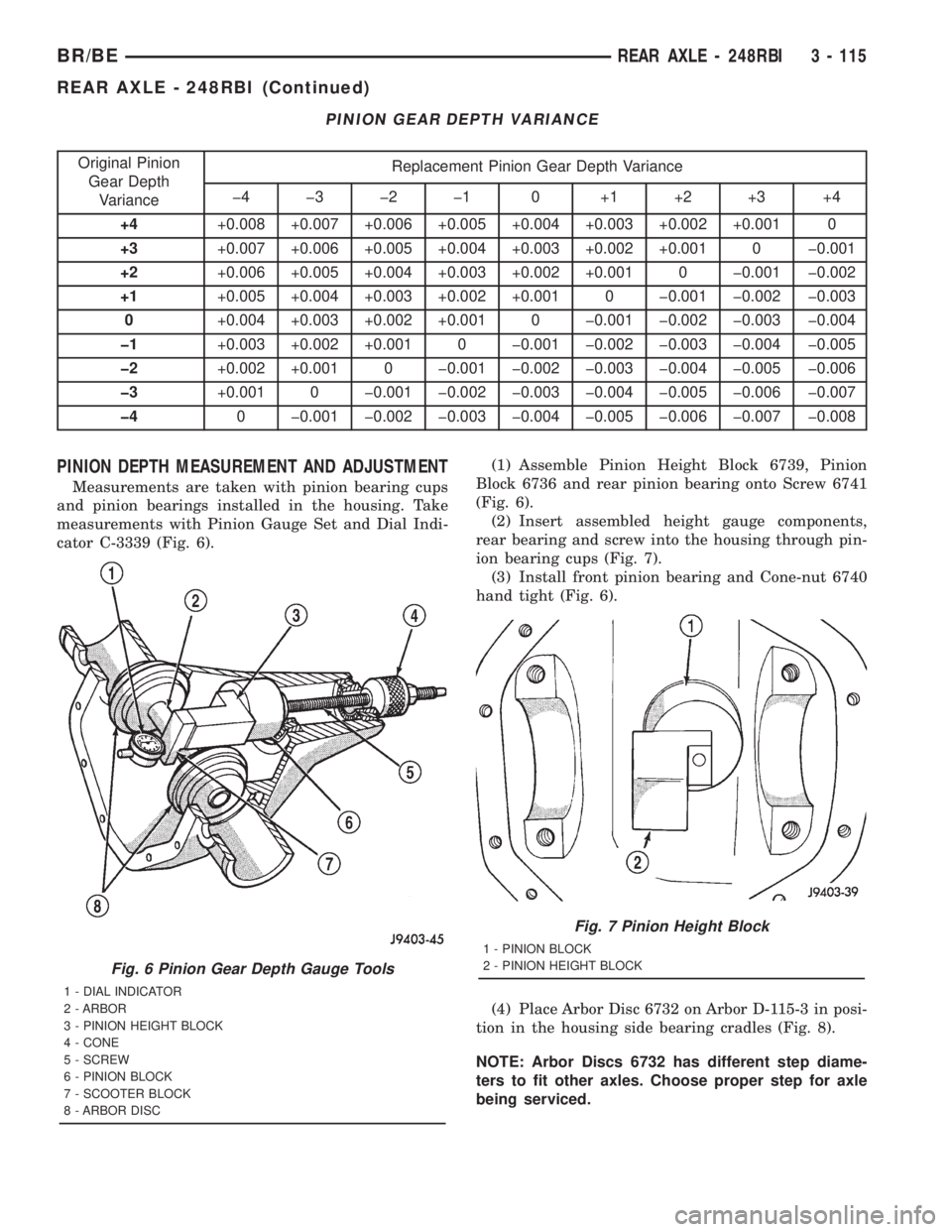
cator C-3339 (Fig. 6).(1) Assemble Pinion Height Block 6739, Pinion
Block 6736 and rear pinion bearing onto Screw 6741
(Fig. 6).
(2) Insert assembled height gauge components,
rear bearing and screw into the housing through pin-
ion bearing cups (Fig. 7).
(3) Install front pinion bearing and Cone-nut 6740
hand tight (Fig. 6).
(4) Place Arbor Disc 6732 on Arbor D-115-3 in posi-
tion in the housing side bearing cradles (Fig. 8).
NOTE: Arbor Discs 6732 has different step diame-
ters to fit other axles. Choose proper step for axle
being serviced.
Fig. 6 Pinion Gear Depth Gauge Tools
1 - DIAL INDICATOR
2 - ARBOR
3 - PINION HEIGHT BLOCK
4 - CONE
5 - SCREW
6 - PINION BLOCK
7 - SCOOTER BLOCK
8 - ARBOR DISC
Fig. 7 Pinion Height Block
1 - PINION BLOCK
2 - PINION HEIGHT BLOCK
BR/BEREAR AXLE - 248RBI 3 - 115
REAR AXLE - 248RBI (Continued)
Page 219 of 2889
PINION GEAR DEPTH VARIANCE
Original Pinion
Gear Depth
VarianceReplacement Pinion Gear Depth Variance
þ4 þ3 þ2 þ1 0 +1 +2 +3 +4
+4+0.008 +0.007 +0.006 +0.005 +0.004 +0.003 +0.002 +0.001 0
+3+0.007 +0.006 +0.005 +0.004 +0.003 +0.002 +0.001 0 þ0.001
+2+0.006 +0.005 +0.004 +0.003 +0.002 +0.001 0 þ0.001 þ0.002
+1+0.005 +0.004 +0.003 +0.002 +0.001 0 þ0.001 þ0.002 þ0.003
0+0.004 +0.003 +0.002 +0.001 0 þ0.001 þ0.002 þ0.003 þ0.004
þ1+0.003 +0.002 +0.001 0 þ0.001 þ0.002 þ0.003 þ0.004 þ0.005
þ2+0.002 +0.001 0 þ0.001 þ0.002 þ0.003 þ0.004 þ0.005 þ0.006
þ3+0.001 0 þ0.001 þ0.002 þ0.003 þ0.004 þ0.005 þ0.006 þ0.007
þ40 þ0.001 þ0.002 þ0.003 þ0.004 þ0.005 þ0.006 þ0.007 þ0.008
PINION DEPTH MEASUREMENT AND ADJUSTMENT
Measurements are taken with pinion bearing cups
and pinion bearings installed in the housing. Take
measurements with Pinion Gauge Set and Dial Indi-
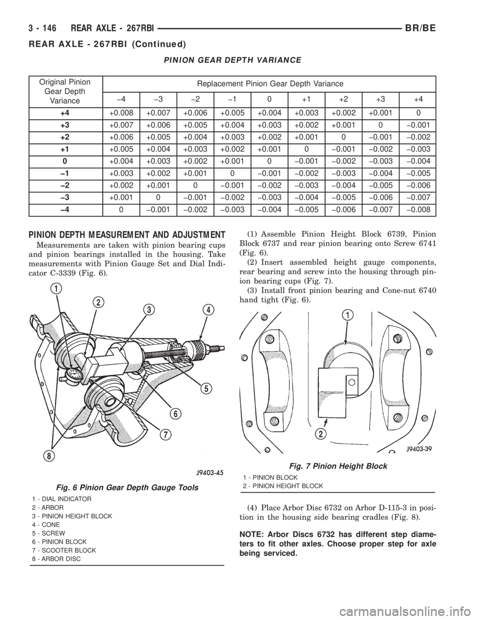
cator C-3339 (Fig. 6).(1) Assemble Pinion Height Block 6739, Pinion
Block 6737 and rear pinion bearing onto Screw 6741
(Fig. 6).
(2) Insert assembled height gauge components,
rear bearing and screw into the housing through pin-
ion bearing cups (Fig. 7).
(3) Install front pinion bearing and Cone-nut 6740
hand tight (Fig. 6).
(4) Place Arbor Disc 6732 on Arbor D-115-3 in posi-
tion in the housing side bearing cradles (Fig. 8).
NOTE: Arbor Discs 6732 has different step diame-
ters to fit other axles. Choose proper step for axle
being serviced.
Fig. 6 Pinion Gear Depth Gauge Tools
1 - DIAL INDICATOR
2 - ARBOR
3 - PINION HEIGHT BLOCK
4 - CONE
5 - SCREW
6 - PINION BLOCK
7 - SCOOTER BLOCK
8 - ARBOR DISC
Fig. 7 Pinion Height Block
1 - PINION BLOCK
2 - PINION HEIGHT BLOCK
3 - 146 REAR AXLE - 267RBIBR/BE
REAR AXLE - 267RBI (Continued)
Page 248 of 2889
PINION GEAR DEPTH VARIANCE
Original Pinion
Gear Depth
VarianceReplacement Pinion Gear Depth Variance
þ4 þ3 þ2 þ1 0 +1 +2 +3 +4
+4+0.008 +0.007 +0.006 +0.005 +0.004 +0.003 +0.002 +0.001 0
+3+0.007 +0.006 +0.005 +0.004 +0.003 +0.002 +0.001 0 þ0.001
+2+0.006 +0.005 +0.004 +0.003 +0.002 +0.001 0 þ0.001 þ0.002
+1+0.005 +0.004 +0.003 +0.002 +0.001 0 þ0.001 þ0.002 þ0.003
0+0.004 +0.003 +0.002 +0.001 0 þ0.001 þ0.002 þ0.003 þ0.004
þ1+0.003 +0.002 +0.001 0 þ0.001 þ0.002 þ0.003 þ0.004 þ0.005
þ2+0.002 +0.001 0 þ0.001 þ0.002 þ0.003 þ0.004 þ0.005 þ0.006
þ3+0.001 0 þ0.001 þ0.002 þ0.003 þ0.004 þ0.005 þ0.006 þ0.007
þ40 þ0.001 þ0.002 þ0.003 þ0.004 þ0.005 þ0.006 þ0.007 þ0.008
PINION DEPTH MEASUREMENT AND ADJUSTMENT
Measurements are taken with pinion cups and pin-
ion bearings installed in housing. Take measure-
ments with a Pinion Gauge Set 6730 and Dial
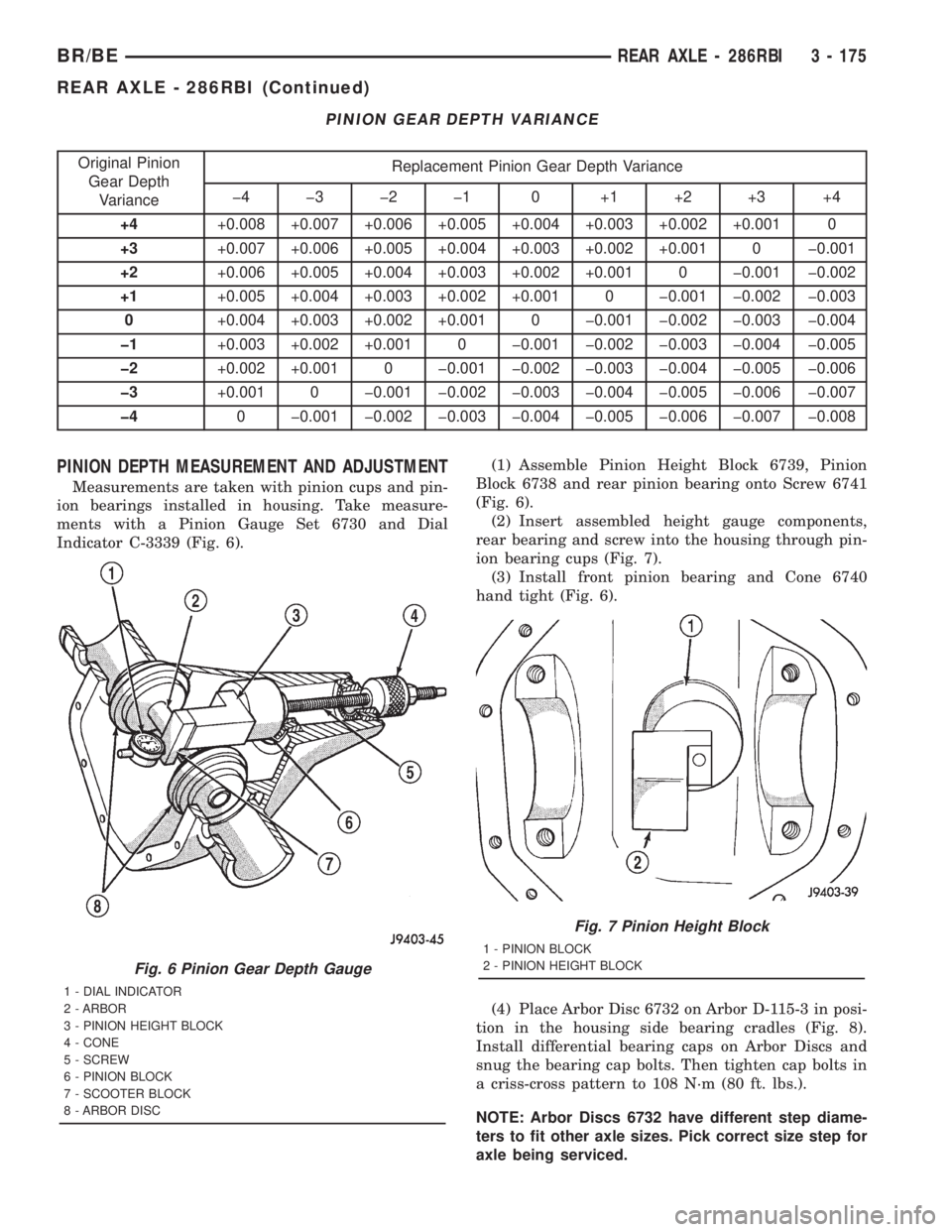
Indicator C-3339 (Fig. 6).(1) Assemble Pinion Height Block 6739, Pinion
Block 6738 and rear pinion bearing onto Screw 6741
(Fig. 6).
(2) Insert assembled height gauge components,
rear bearing and screw into the housing through pin-
ion bearing cups (Fig. 7).
(3) Install front pinion bearing and Cone 6740
hand tight (Fig. 6).
(4) Place Arbor Disc 6732 on Arbor D-115-3 in posi-
tion in the housing side bearing cradles (Fig. 8).
Install differential bearing caps on Arbor Discs and
snug the bearing cap bolts. Then tighten cap bolts in
a criss-cross pattern to 108 N´m (80 ft. lbs.).
NOTE: Arbor Discs 6732 have different step diame-
ters to fit other axle sizes. Pick correct size step for
axle being serviced.
Fig. 6 Pinion Gear Depth Gauge
1 - DIAL INDICATOR
2 - ARBOR
3 - PINION HEIGHT BLOCK
4 - CONE
5 - SCREW
6 - PINION BLOCK
7 - SCOOTER BLOCK
8 - ARBOR DISC
Fig. 7 Pinion Height Block
1 - PINION BLOCK
2 - PINION HEIGHT BLOCK
BR/BEREAR AXLE - 286RBI 3 - 175
REAR AXLE - 286RBI (Continued)
Page 317 of 2889
Oil contamination indicates a leak at either the
rear main seal or transmission input shaft. Oil leak-
age produces a residue of oil on the housing interior
and on the clutch cover and flywheel. Heat buildup
caused by slippage between the cover, disc and fly-
wheel, can sometimes bake the oil residue onto the
components. The glaze-like residue ranges in color
from amber to black.
Road splash contamination means dirt/water is
entering the clutch housing due to loose bolts, hous-
ing cracks or through hydraulic line openings. Driv-
ing through deep water puddles can force water/road
splash into the housing through such openings.
Clutch fluid leaks are usually from damaged slave
cylinder push rod seals.
IMPROPER RELEASE OR CLUTCH ENGAGEMENT
Clutch release or engagement problems are caused
by wear or damage to one or more clutch compo-
nents. A visual inspection of the release components
will usually reveal the problem part.
Release problems can result in hard shifting and
noise. Items to look for are: leaks at the clutch cylin-
ders and interconnecting line; loose slave cylinder
bolts; worn/loose release fork and pivot stud; dam-
aged release bearing; and a worn clutch disc, or pres-
sure plate.
Normal condensation in vehicles that are stored or
out of service for long periods of time can generate
enough corrosion to make the disc stick to the fly-
wheel, or pressure plate. If this condition is experi-
enced, correction only requires that the disc be
loosened manually through the inspection plate open-
ing.
Engagement problems usually result in slip, chat-
ter/shudder, and noisy operation. The primary causes
are clutch disc contamination; clutch disc wear; mis-
alignment, or distortion; flywheel damage; or a com-
bination of the foregoing. A visual inspection is
required to determine the part actually causing the
problem.
CLUTCH MISALIGNMENT
Clutch components must be in proper alignment
with the crankshaft and transmission input shaft.
Misalignment caused by excessive runout or warpage
of any clutch component will cause grab, chatter and
improper clutch release.
CLUTCH COVER AND DISC RUNOUT
Check the clutch disc before installation. Axial
(face) runout of anewdisc should not exceed 0.50
mm (0.020 in.). Measure runout about 6 mm (1/4 in.)
from the outer edge of the disc facing. Obtain
another disc if runout is excessive.Check condition of the clutch before installation. A
warped cover or diaphragm spring will cause grab
and incomplete release or engagement. Be careful
when handling the cover and disc. Impact can distort
the cover, diaphragm spring, release fingers and the
hub of the clutch disc.
Use an alignment tool when positioning the disc on
the flywheel. The tool prevents accidental misalign-
ment which could result in cover distortion and disc
damage.
A frequent cause of clutch cover distortion (and con-
sequent misalignment) is improper bolt tightening.
CLUTCH FLYWHEEL RUNOUT
Check flywheel runout whenever misalignment is
suspected. Flywheel runout should not exceed 0.08
mm (0.003 in.). Measure runout at the outer edge of
the flywheel face with a dial indicator. Mount the
indicator on the rear face of the engine block.
Common causes of runout are:
²heat warpage
²improper machining
²incorrect bolt tightening
²improper seating on crankshaft flange shoulder
²foreign material on crankshaft flange
Flywheel machining is not recommended. The fly-
wheel clutch surface is machined to a unique contour
and machining will negate this feature. However,
minor flywheel scoring can be cleaned up by hand with
180 grit emery, or with surface grinding equipment.
Remove only enough material to reduce scoring
(approximately 0.001 - 0.003 in.). Heavy stock removal
isnot recommended.
Replace the flywheel if scoring
is severe and deeper than 0.076 mm (0.003 in.).
Excessive stock removal can result in flywheel crack-
ing or warpage after installation; it can also weaken
the flywheel and interfere with proper clutch release.
Clean the crankshaft flange before mounting the
flywheel. Dirt and grease on the flange surface may
cock the flywheel causing excessive runout. Use new
bolts when remounting a flywheel and secure the
bolts with MopartLock And Seal. Tighten flywheel
bolts to specified torque only. Overtightening can dis-
tort the flywheel hub causing runout.
DIAGNOSIS CHART
The clutch inspection chart (Fig. 3) outlines items to
be checked before and during clutch installation. Use
the chart as a check list to help avoid overlooking
potential problem sources during service operations.
The diagnosis charts describe common clutch prob-
lems, causes and correction. Fault conditions are listed
at the top of each chart. Conditions, causes and correc-
tive action are outlined in the indicated columns.
The charts are provided as a convenient reference
when diagnosing faulty clutch operation.
6 - 4 CLUTCHBR/BE
CLUTCH (Continued)
Page 333 of 2889
The clutch fluid reservoir, master cylinder, slave
cylinder and fluid lines are pre-filled with fluid at
the factory during assembly operations.
The hydraulic system should not require additional
fluid under normal circumstances.The reservoir
fluid level will actually increase as normal
clutch wear occurs. Avoid overfilling, or remov-
ing fluid from the reservoir.
Clutch fluid level is checked at the master cylinder
reservoir. An indicator ring is provided on the outside
of the reservoir. With the cap and diaphragm
removed, fluid level should not be above indicator
ring.
To avoid contaminating the hydraulic fluid during
inspection, wipe reservoir and cover clean before
removing the cap.
OPERATION
The clutch linkage uses hydraulic pressure to oper-
ate the clutch. Depressing the clutch pedal develops
fluid pressure in the clutch master cylinder. This
pressure is transmitted to the slave cylinder through
a connecting line. In turn, the slave cylinder operates
the clutch release lever.
The slave cylinder has an integral spring which
preloads the release bearing against the clutch dia-
phragm fingers to maintain zero free-play.
Slave cylinder force causes the release lever to
move the release bearing into contact with the dia-
phragm spring. As additional force is applied, the
bearing presses the diaphragm spring fingers inward
on the fulcrums. This action moves the pressure
plate rearward relieving clamp force on the disc.
REMOVAL
The factory installed hydraulic linkage has a quick
disconnect at the slave cylinder. This fitting should
not be disconnected or tampered with. The hydraulic
linkage is serviced as an assembly only, but it comes
as two pieces to ease installation. Once the clutch
hydraulic line is connected to the slave cylinder, it
should not be disconnected. The individual compo-
nents that form the linkage assembly cannot be over-
hauled or serviced separately.
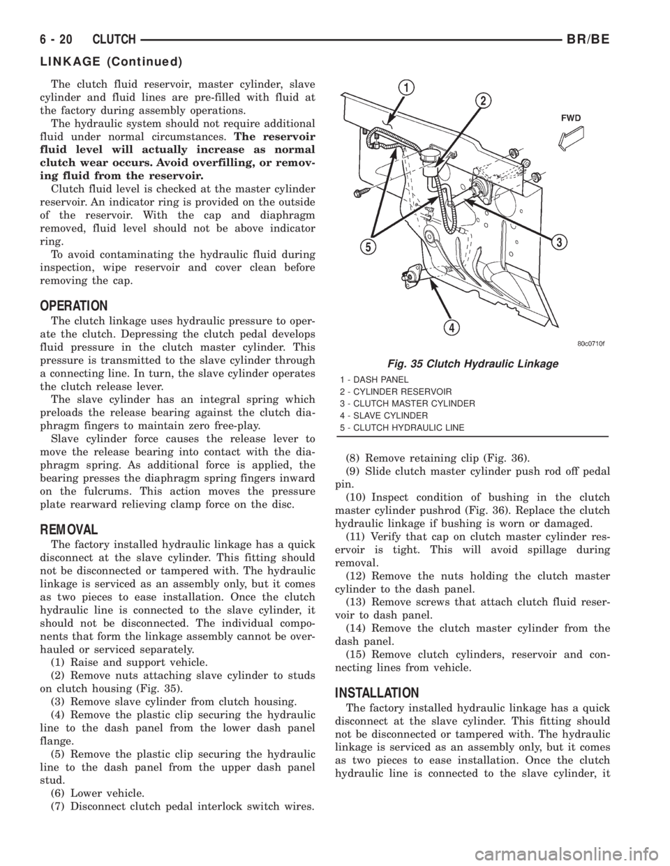
(1) Raise and support vehicle.
(2) Remove nuts attaching slave cylinder to studs
on clutch housing (Fig. 35).
(3) Remove slave cylinder from clutch housing.
(4) Remove the plastic clip securing the hydraulic
line to the dash panel from the lower dash panel
flange.
(5) Remove the plastic clip securing the hydraulic
line to the dash panel from the upper dash panel
stud.
(6) Lower vehicle.
(7) Disconnect clutch pedal interlock switch wires.(8) Remove retaining clip (Fig. 36).
(9) Slide clutch master cylinder push rod off pedal
pin.
(10) Inspect condition of bushing in the clutch
master cylinder pushrod (Fig. 36). Replace the clutch
hydraulic linkage if bushing is worn or damaged.
(11) Verify that cap on clutch master cylinder res-
ervoir is tight. This will avoid spillage during
removal.
(12) Remove the nuts holding the clutch master
cylinder to the dash panel.
(13) Remove screws that attach clutch fluid reser-
voir to dash panel.
(14) Remove the clutch master cylinder from the
dash panel.
(15) Remove clutch cylinders, reservoir and con-
necting lines from vehicle.
INSTALLATION
The factory installed hydraulic linkage has a quick
disconnect at the slave cylinder. This fitting should
not be disconnected or tampered with. The hydraulic
linkage is serviced as an assembly only, but it comes
as two pieces to ease installation. Once the clutch
hydraulic line is connected to the slave cylinder, it
Fig. 35 Clutch Hydraulic Linkage
1 - DASH PANEL
2 - CYLINDER RESERVOIR
3 - CLUTCH MASTER CYLINDER
4 - SLAVE CYLINDER
5 - CLUTCH HYDRAULIC LINE
6 - 20 CLUTCHBR/BE
LINKAGE (Continued)
Page 351 of 2889
(3) Fill coolant reserve/overflow tank to the FULL
mark.
(4) Start and operate engine until thermostat
opens. Upper radiator hose should be warm to touch.
(5) If necessary, add 50/50 water and antifreeze
mixture to the coolant reserve/overflow tank to main-
tain coolant level. This level should be between the
ADD and FULL marks. The level in the reserve/over-
flow tank may drop below the ADD mark after three
or four warm-up and cool-down cycles.
STANDARD PROCEDUREÐADDING
ADDITIONAL COOLANT
Do not remove radiator cap to add coolant to
system.When adding coolant to maintain correct
level, do so at coolant reserve/overflow tank. Use a
50/50 mixture of ethylene glycol antifreeze containing
Alugard 340-2yand low mineral content water.
Remove radiator cap only for testing or when refill-
ing system after service. Removing cap unnecessarily
can cause loss of coolant and allow air to enter sys-
tem, which produces corrosion.
STANDARD PROCEDUREÐCOOLANT LEVEL
CHECK
NOTE: Do not remove radiator cap for routine cool-
ant level inspections. The coolant level can be
checked at coolant recovery bottle .
The coolant reserve/overflow system provides a
quick method for determining coolant level without
removing radiator pressure cap. With engine not run-
ning, open the coolant recovery bottle cap and
remove coolant level indicator dipstick to observe
coolant level in coolant recovery bottle. The coolant
level should be between ADD and FULL marks. If
the coolant level is at or below the ADD mark, fill
the recovery bottle with a 50/50 mixture of antifreeze
and water ONE QUART AT A TIME. Repeat this pro-
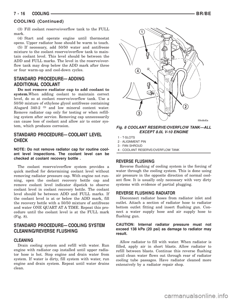
cedure until the coolant level is at the FULL mark
(Fig. 8).
STANDARD PROCEDUREÐCOOLING SYSTEM
CLEANING/REVERSE FLUSHING
CLEANING
Drain cooling system and refill with water. Run
engine with radiator cap installed until upper radia-
tor hose is hot. Stop engine and drain water from
system. If water is dirty, fill system with water, run
engine and drain system. Repeat until water drains
clean.
REVERSE FLUSHING
Reverse flushing of cooling system is the forcing of
water through the cooling system. This is done using
air pressure in the opposite direction of normal cool-
ant flow. It is usually only necessary with very dirty
systems with evidence of partial plugging.
REVERSE FLUSHING RADIATOR
Disconnect radiator hoses from radiator inlet and
outlet. Attach a section of radiator hose to radiator
bottom outlet fitting and insert flushing gun. Con-
nect a water supply hose and air supply hose to
flushing gun.
CAUTION: Internal radiator pressure must not
exceed 138 kPa (20 psi) as damage to radiator may
result.
Allow radiator to fill with water. When radiator is
filled, apply air in short blasts. Allow radiator to
refill between blasts. Continue this reverse flushing
until clean water flows out through rear of radiator
cooling tube passages. Have radiator cleaned more
extensively by a radiator repair shop.
Fig. 8 COOLANT RESERVE/OVERFLOW TANKÐALL
EXCEPT 8.0L V-10 ENGINE
1 - T-SLOTS
2 - ALIGNMENT PIN
3 - FAN SHROUD
4 - COOLANT RESERVE/OVERFLOW TANK
7 - 16 COOLINGBR/BE
COOLING (Continued)
Page 446 of 2889
CHIME/BUZZER
TABLE OF CONTENTS
page page
CHIME WARNING SYSTEM
DESCRIPTION............................1
OPERATION.............................1DIAGNOSIS AND TESTING..................2
CHIME WARNING SYSTEM................2
CHIME WARNING SYSTEM
DESCRIPTION
A chime warning system is standard factory-in-
stalled equipment on this model. The chime warning
system uses a single chime tone generator that is
integral to the Central Timer Module (CTM) to pro-
vide an audible indication of various vehicle condi-
tions that may require the attention of the vehicle
operator. The chime warning system includes the fol-
lowing major components, which are described in fur-
ther detail elsewhere in this service manual:
²Central Timer Module- The Central Timer
Module (CTM) is located under the driver side end of
the instrument panel, inboard of the instrument
panel steering column opening. The CTM contains an
integral chime tone generator to provide all of the
proper chime warning system features based upon
the monitored inputs.
²Door Ajar Switch- A door ajar switch is inte-
gral to the driver side front door latch. This switch
provides an input to the chime warning system indi-
cating whether the driver side front door is open or
closed.
²Headlamp Switch- The headlamp switch is
located on the instrument panel outboard of the
steering column. The headlamp switch provides an
input to the chime warning system indicating when
the exterior lamps are turned On or Off.
²Ignition Switch- A key-in ignition switch is
integral to the ignition switch. The key-in ignition
switch provides an input to the chime warning sys-
tem indicating whether a key is present in the igni-
tion lock cylinder.
²Seat Belt Switch- A seat belt switch is inte-
gral to the driver side front seat belt retractor unit.
The seat belt switch provides an input to the chime
warning system indicating whether the driver side
front seat belt is fastened.
Hard wired circuitry connects many of the chime
warning system components to each other through
the electrical system of the vehicle. These hard wired
circuits are integral to several wire harnesses, which
are routed throughout the vehicle and retained bymany different methods. These circuits may be con-
nected to each other, to the vehicle electrical system
and to the chime warning system components
through the use of a combination of soldered splices,
splice block connectors, and many different types of
wire harness terminal connectors and insulators.
Refer to the appropriate wiring information. The wir-
ing information includes wiring diagrams, proper
wire and connector repair procedures, further details
on wire harness routing and retention, as well as
pin-out and location views for the various wire har-
ness connectors, splices and grounds.
The CTM chime warning system circuitry and the
integral chime tone generator cannot be adjusted or
repaired. If the CTM or the chime tone generator are
damaged or faulty, the CTM unit must be replaced.
OPERATION
The chime warning system is designed to provide an
audible output as an indication of various conditions
that may require the attention or awareness of the
vehicle operator. The chime warning system compo-
nents operate on battery current received through a
fused B(+) fuse in the Junction Block (JB) on a non-
switched fused B(+) circuit so that the system may
operate regardless of the ignition switch position.
The chime warning system provides an audible
indication to the vehicle operator under the following
conditions:
²Fasten Seat Belt Warning- The Central
Timer Module (CTM) chime tone generator will gen-
erate repetitive chime tones at a slow rate to
announce that a hard wired input from the seat belt
switch to the Electro-Mechanical Instrument Cluster
(EMIC) indicates that the driver side front seat belt
is not fastened with the ignition switch in the On
position. Unless the driver side front seat belt is fas-
tened, the chimes will continue to sound for a dura-
tion of about seven seconds each time the ignition
switch is turned to the On position or until the driver
side front seat belt is fastened, whichever occurs
first. This chime tone is based upon a hard wired
chime request input to the CTM from the EMIC, but
is not related to the operation of the EMIC ªSeatbeltº
indicator.
BR/BECHIME/BUZZER 8B - 1