2001 DODGE RAM intake manifold torq
[x] Cancel search: intake manifold torqPage 383 of 2889

ENGINE COOLANT TEMP
SENSOR - 3.9L/5.2L/5.9L
DESCRIPTION
The Engine Coolant Temperature (ECT) sensor is
used to sense engine coolant temperature. The sensor
protrudes into an engine water jacket.
The ECT sensor is a two-wire Negative Thermal
Coefficient (NTC) sensor. Meaning, as engine coolant
temperature increases, resistance (voltage) in the
sensor decreases. As temperature decreases, resis-
tance (voltage) in the sensor increases.
OPERATION
At key-on, the Powertrain Control Module (PCM)
sends out a regulated 5 volt signal to the ECT sensor.
The PCM then monitors the signal as it passes
through the ECT sensor to the sensor ground (sensor
return).
When the engine is cold, the PCM will operate in
Open Loop cycle. It will demand slightly richer air-
fuel mixtures and higher idle speeds. This is done
until normal operating temperatures are reached.
The PCM uses inputs from the ECT sensor for the
following calculations:
²for engine coolant temperature gauge operation
through CCD or PCI (J1850) communications
²Injector pulse-width
²Spark-advance curves
²ASD relay shut-down times
²Idle Air Control (IAC) motor key-on steps
²Pulse-width prime-shot during cranking
²O2 sensor closed loop times
²Purge solenoid on/off times
²EGR solenoid on/off times (if equipped)
²Leak Detection Pump operation (if equipped)²Radiator fan relay on/off times (if equipped)
²Target idle speed
REMOVAL
WARNING: HOT, PRESSURIZED COOLANT CAN
CAUSE INJURY BY SCALDING. COOLING SYSTEM
MUST BE PARTIALLY DRAINED BEFORE REMOV-
ING THE COOLANT TEMPERATURE SENSOR.
REFER TO GROUP 7, COOLING.
(1) Partially drain cooling system (Refer to 7 -
COOLING - STANDARD PROCEDURE).
(2) Remove air cleaner assembly.
(3) Disconnect electrical connector from sensor
(Fig. 14).
(4)Engines with air conditioning:When
removing the connector from sensor, do not pull
directly on wiring harness. Fabricate an L-shaped
hook tool from a coat hanger (approximately eight
inches long). Place the hook part of tool under the
connector for removal. The connector is snapped onto
the sensor. It is not equipped with a lock type tab.
(5) Remove sensor from intake manifold.
INSTALLATION
(1) Install sensor.
(2) Tighten to 6±8 N´m (55±75 in. lbs.) torque.
(3) Connect electrical connector to sensor. The sen-
sor connector is symmetrical (not indexed). It can be
installed to the sensor in either direction.
(4) Install air cleaner assembly.
(5) Refill cooling system (Refer to 7 - COOLING -
STANDARD PROCEDURE).
Fig. 13 Block HeaterÐDiesel Engine
1 - BLOCK HEATER
Fig. 14 Engine Coolant Temperature
1 - GENERATOR
2 - A/C COMPRESSOR
3 - ENGINE COOLANT TEMPERATURE SENSOR
4 - ELEC. CONN.
7 - 48 ENGINEBR/BE
ENGINE BLOCK HEATER - 5.9L DIESEL (Continued)
Page 386 of 2889
(4) Position thermostat housing to intake manifold.
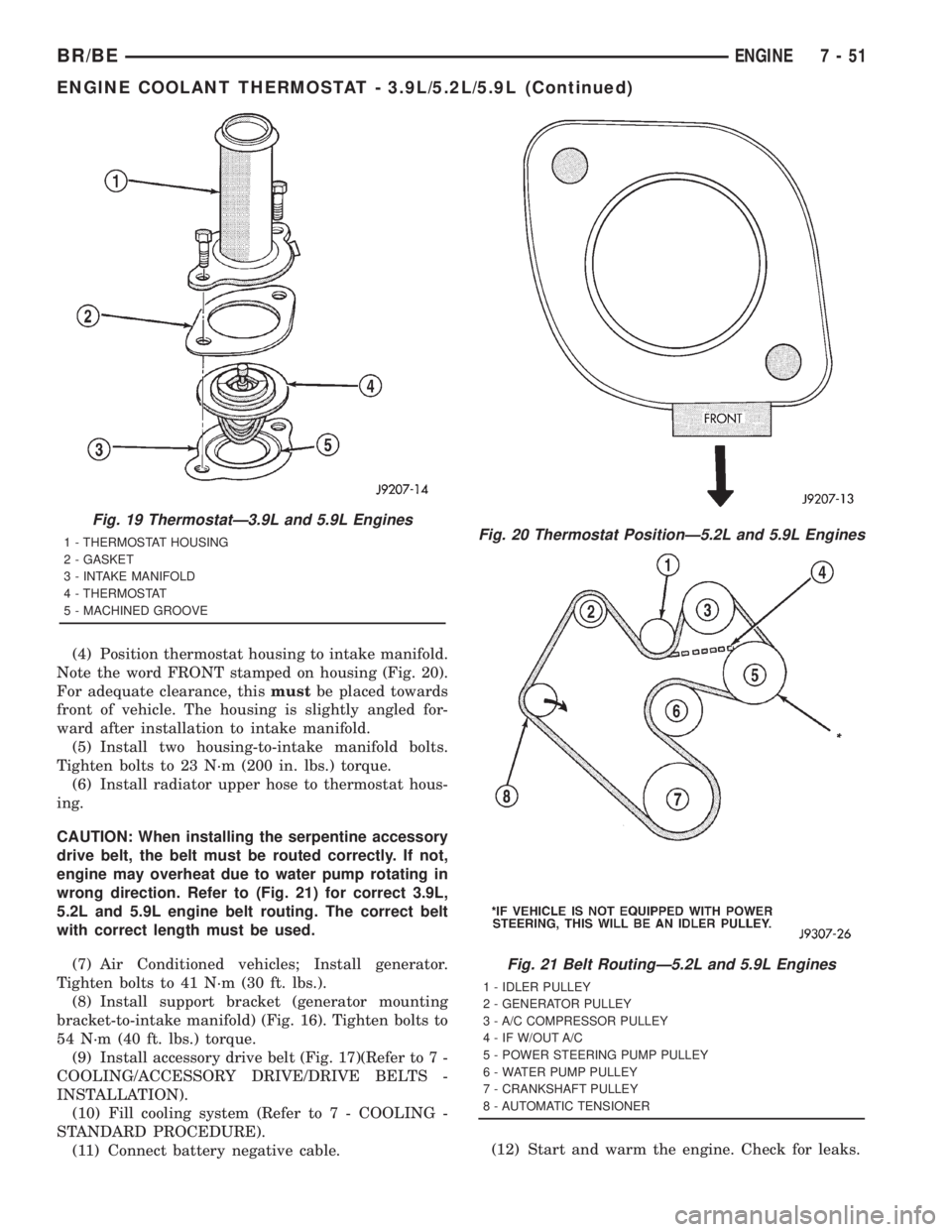
Note the word FRONT stamped on housing (Fig. 20).
For adequate clearance, thismustbe placed towards
front of vehicle. The housing is slightly angled for-
ward after installation to intake manifold.
(5) Install two housing-to-intake manifold bolts.
Tighten bolts to 23 N´m (200 in. lbs.) torque.
(6) Install radiator upper hose to thermostat hous-
ing.
CAUTION: When installing the serpentine accessory
drive belt, the belt must be routed correctly. If not,
engine may overheat due to water pump rotating in
wrong direction. Refer to (Fig. 21) for correct 3.9L,
5.2L and 5.9L engine belt routing. The correct belt
with correct length must be used.
(7) Air Conditioned vehicles; Install generator.
Tighten bolts to 41 N´m (30 ft. lbs.).
(8) Install support bracket (generator mounting
bracket-to-intake manifold) (Fig. 16). Tighten bolts to
54 N´m (40 ft. lbs.) torque.
(9) Install accessory drive belt (Fig. 17)(Refer to 7 -
COOLING/ACCESSORY DRIVE/DRIVE BELTS -
INSTALLATION).
(10) Fill cooling system (Refer to 7 - COOLING -
STANDARD PROCEDURE).
(11) Connect battery negative cable.(12) Start and warm the engine. Check for leaks.
Fig. 19 ThermostatÐ3.9L and 5.9L Engines
1 - THERMOSTAT HOUSING
2 - GASKET
3 - INTAKE MANIFOLD
4 - THERMOSTAT
5 - MACHINED GROOVEFig. 20 Thermostat PositionÐ5.2L and 5.9L Engines
Fig. 21 Belt RoutingÐ5.2L and 5.9L Engines
1 - IDLER PULLEY
2 - GENERATOR PULLEY
3 - A/C COMPRESSOR PULLEY
4 - IF W/OUT A/C
5 - POWER STEERING PUMP PULLEY
6 - WATER PUMP PULLEY
7 - CRANKSHAFT PULLEY
8 - AUTOMATIC TENSIONER
BR/BEENGINE 7 - 51
ENGINE COOLANT THERMOSTAT - 3.9L/5.2L/5.9L (Continued)
Page 389 of 2889

cial Seal Tool number C-3995-A with handle tool
number C-4171.
(4) Install thermostat into recessed machined
groove on intake manifold (Fig. 25).
(5) Install thermostat housing (Fig. 25).
(6) Install housing-to-intake manifold bolts.
Tighten bolts to 25 N´m (220 in. lbs.) torque.
CAUTION: Housing bolts should be tightened
evenly to prevent damage to housing and to pre-
vent leaks.
(7) Connect the wiring to both sensors.
(8) Install the upper radiator hose and hose clamp
to thermostat housing.
(9) Install support rod.
(10) Fill cooling system (Refer to 7 - COOLING -
STANDARD PROCEDURE).
(11) Connect negative battery cable to battery.
(12) Start and warm engine. Check for leaks.
ENGINE COOLANT
THERMOSTAT - 5.9L DIESEL
DESCRIPTION
CAUTION: Do not operate an engine without a ther-
mostat, except for servicing or testing. An engine
with the thermostat removed will operate in the
radiator bypass mode, causing an overheat condi-
tion.
The thermostat of the 5.9L diesel engine is located
in the front of the cylinder head, underneath the
water outlet connector (Fig. 26).
The same thermostat is used for winter and sum-
mer seasons. An engine should not be operated with-
out a thermostat, except for servicing or testing.
Operating without a thermostat causes longer engine
warmup time, unreliable warmup performance,
increased exhaust emissions and crankcase condensa-
tion that can result in sludge formation.
OPERATION
The wax pellet is located in a sealed container at
the spring end of the thermostat. When heated, the
pellet expands, overcoming closing spring tension
and water pump pressure to force the valve to open.
DIAGNOSIS AND TESTINGÐTHERMOSTAT
The cooling system used with the diesel engine
provides the extra coolant capacity and extra cooling
protection needed for higher GVWR (Gross Vehicle
Weight Rating) and GCWR (Gross Combined Weight
Rating) vehicles.This system capacity will not effect warm up or
cold weather operating characteristics if the thermo-
stat is operating properly. This is because coolant
will be held in the engine until it reaches the ther-
mostat ªsetº temperature.
Diesel engines, due to their inherent efficiency are
slower to warm up than gasoline powered engines,
and will operate at lower temperatures when the
vehicle is unloaded. Because of this, lower tempera-
ture gauge readings for diesel versus gasoline
engines may, at times be normal.
Typically, complaints of low engine coolant temper-
ature are observed as low heater output when com-
bined with cool or cold outside temperatures.
To help promote faster engine warm-up, the elec-
tric engine block heater must be used with cool or
cold outside temperatures. This will help keep the
engine coolant warm when the vehicle is parked. Use
the block heater if the outside temperature is below
4ÉC (40ÉF).Do not use the block heater if the
outside temperature is above 4ÉC (40ÉF).
A ªCold Weather Coverº is available from the parts
department through the Mopar Accessories product
line. This accessory cover is designed to block airflow
entering the radiator and engine compartment to
promote faster engine warm-up. It attaches to the
front of the vehicle at the grill opening.The cover is
Fig. 26 ThermostatÐ5.9L DieselÐTypical
1 - WATER OUTLET CONNECTOR
2 - THERMOSTAT HOUSING
3 - THERMOSTAT
7 - 54 ENGINEBR/BE
ENGINE COOLANT THERMOSTAT - 8.0L (Continued)
Page 412 of 2889
REMOVALÐWATER PUMP BYPASS HOSE
WITHOUT AIR CONDITIONING
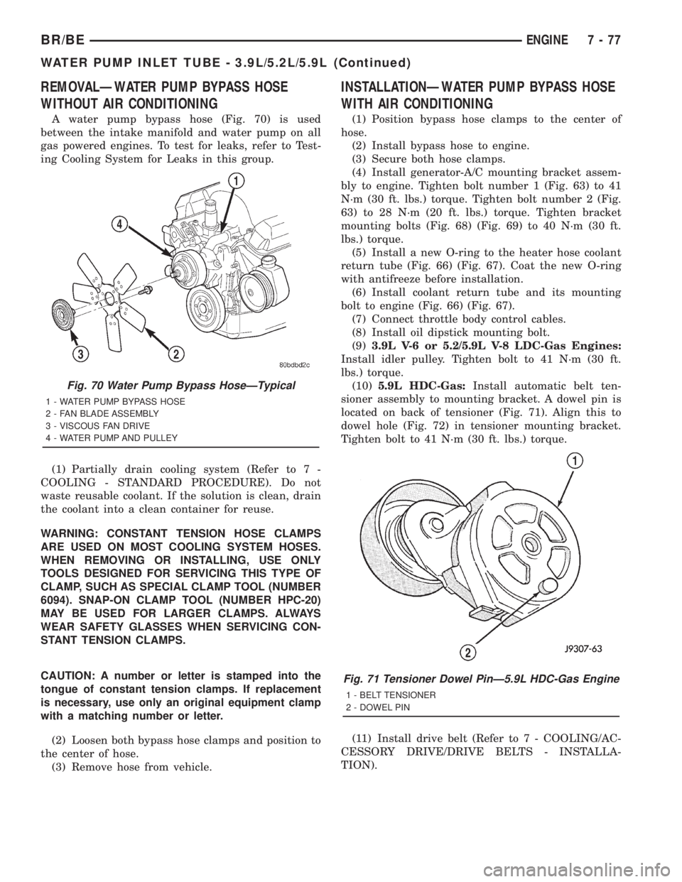
A water pump bypass hose (Fig. 70) is used
between the intake manifold and water pump on all
gas powered engines. To test for leaks, refer to Test-
ing Cooling System for Leaks in this group.
(1) Partially drain cooling system (Refer to 7 -
COOLING - STANDARD PROCEDURE). Do not
waste reusable coolant. If the solution is clean, drain
the coolant into a clean container for reuse.
WARNING: CONSTANT TENSION HOSE CLAMPS
ARE USED ON MOST COOLING SYSTEM HOSES.
WHEN REMOVING OR INSTALLING, USE ONLY
TOOLS DESIGNED FOR SERVICING THIS TYPE OF
CLAMP, SUCH AS SPECIAL CLAMP TOOL (NUMBER
6094). SNAP-ON CLAMP TOOL (NUMBER HPC-20)
MAY BE USED FOR LARGER CLAMPS. ALWAYS
WEAR SAFETY GLASSES WHEN SERVICING CON-
STANT TENSION CLAMPS.
CAUTION: A number or letter is stamped into the
tongue of constant tension clamps. If replacement
is necessary, use only an original equipment clamp
with a matching number or letter.
(2) Loosen both bypass hose clamps and position to
the center of hose.
(3) Remove hose from vehicle.
INSTALLATIONÐWATER PUMP BYPASS HOSE
WITH AIR CONDITIONING
(1) Position bypass hose clamps to the center of
hose.
(2) Install bypass hose to engine.
(3) Secure both hose clamps.
(4) Install generator-A/C mounting bracket assem-
bly to engine. Tighten bolt number 1 (Fig. 63) to 41
N´m (30 ft. lbs.) torque. Tighten bolt number 2 (Fig.
63) to 28 N´m (20 ft. lbs.) torque. Tighten bracket
mounting bolts (Fig. 68) (Fig. 69) to 40 N´m (30 ft.
lbs.) torque.
(5) Install a new O-ring to the heater hose coolant
return tube (Fig. 66) (Fig. 67). Coat the new O-ring
with antifreeze before installation.
(6) Install coolant return tube and its mounting
bolt to engine (Fig. 66) (Fig. 67).
(7) Connect throttle body control cables.
(8) Install oil dipstick mounting bolt.
(9)3.9L V-6 or 5.2/5.9L V-8 LDC-Gas Engines:
Install idler pulley. Tighten bolt to 41 N´m (30 ft.
lbs.) torque.
(10)5.9L HDC-Gas:Install automatic belt ten-
sioner assembly to mounting bracket. A dowel pin is
located on back of tensioner (Fig. 71). Align this to
dowel hole (Fig. 72) in tensioner mounting bracket.
Tighten bolt to 41 N´m (30 ft. lbs.) torque.
(11) Install drive belt (Refer to 7 - COOLING/AC-
CESSORY DRIVE/DRIVE BELTS - INSTALLA-
TION).
Fig. 71 Tensioner Dowel PinÐ5.9L HDC-Gas Engine
1 - BELT TENSIONER
2 - DOWEL PIN
Fig. 70 Water Pump Bypass HoseÐTypical
1 - WATER PUMP BYPASS HOSE
2 - FAN BLADE ASSEMBLY
3 - VISCOUS FAN DRIVE
4 - WATER PUMP AND PULLEY
BR/BEENGINE 7 - 77
WATER PUMP INLET TUBE - 3.9L/5.2L/5.9L (Continued)
Page 1158 of 2889
(4) A controlled hone motor speed between 200 and
300 RPM is necessary to obtain the proper cross-
hatch angle. The number of up and down strokes per
minute can be regulated to get the desired 50É to 60É
angle. Faster up and down strokes increase the cross-
hatch angle.
(5) After honing, it is necessary that the block be
cleaned to remove all traces of abrasive. Use a brush
to wash parts with a solution of hot water and deter-
gent. Dry parts thoroughly. Use a clean, white, lint-
free cloth to check that the bore is clean. Oil the
bores after cleaning to prevent rusting.
STANDARD PROCEDUREÐHYDROSTATIC
LOCK
CAUTION: DO NOT use the starter motor to rotate
the crankshaft. Severe damage could occur.
When an engine is suspected of hydrostatic lock
(regardless of what caused the problem), follow the
steps below.
(1) Perform the Fuel Pressure Release Procedure
(Refer to 14 - FUEL SYSTEM/FUEL DELIVERY -
STANDARD PROCEDURE).
(2) Disconnect the negative cable(s) from the bat-
tery.
(3) Inspect air cleaner, induction system, and
intake manifold to ensure system is dry and clear of
foreign material.
(4) Place a shop towel around the spark plugs to
catch any fluid that may possibly be under pressure
in the cylinder head. Remove the spark plugs.
(5) With all spark plugs removed, rotate the crank-
shaft using a breaker bar and socket.
(6) Identify the fluid in the cylinders (coolant, fuel,
oil, etc.).
(7) Be sure all fluid has been removed from the
cylinders.
(8) Repair engine or components as necessary to
prevent this problem from occurring again.
(9) Squirt a small amount of engine oil into the
cylinders to lubricate the walls. This will prevent
damage on restart.
(10) Install new spark plugs. Tighten the spark
plugs to 41 N´m (30 ft. lbs.) torque.
(11) Drain engine oil. Remove and discard the oil
filter.
(12) Install the drain plug. Tighten the plug to 34
N´m (25 ft. lbs.) torque.
(13) Install a new oil filter.
(14) Fill engine crankcase with the specified
amount and grade of oil. (Refer to LUBRICATION &
MAINTENANCE - SPECIFICATIONS).
(15) Connect the negative cable(s) to the battery.
(16) Start the engine and check for any leaks.
STANDARD PROCEDUREÐREPAIR DAMAGED
OR WORN THREADS
CAUTION: Be sure that the tapped holes maintain
the original center line.
Damaged or worn threads can be repaired. Essen-
tially, this repair consists of:
²Drilling out worn or damaged threads.
²Tapping the hole with a special Heli-Coil Tap, or
equivalent.
²Installing an insert into the tapped hole to bring
the hole back to its original thread size.
STANDARD PROCEDUREÐFORM-IN-PLACE
GASKETS & SEALERS
There are numerous places where form-in-place
gaskets are used on the engine. Care must be taken
when applying form-in-place gaskets to assure
obtaining the desired results.Do not use form-in-
place gasket material unless specified.Bead size,
continuity, and location are of great importance. Too
thin a bead can result in leakage while too much can
result in spill-over which can break off and obstruct
fluid feed lines. A continuous bead of the proper
width is essential to obtain a leak-free gasket.
There are numerous types of form-in-place gasket
materials that are used in the engine area. Mopart
Engine RTV GEN II, MopartATF-RTV, and Mopart
Gasket Maker gasket materials, each have different
properties and can not be used in place of the other.
MOPARtENGINE RTV GEN II
MopartEngine RTV GEN II is used to seal com-
ponents exposed to engine oil. This material is a spe-
cially designed black silicone rubber RTV that
retains adhesion and sealing properties when
exposed to engine oil. Moisture in the air causes the
material to cure. This material is available in three
ounce tubes and has a shelf life of one year. After one
year this material will not properly cure. Always
inspect the package for the expiration date before
use.
MOPARtATF RTV
MopartATF RTV is a specifically designed black
silicone rubber RTV that retains adhesion and seal-
ing properties to seal components exposed to auto-
matic transmission fluid, engine coolants, and
moisture. This material is available in three ounce
tubes and has a shelf life of one year. After one year
this material will not properly cure. Always inspect
the package for the expiration date before use.
MOPARtGASKET MAKER
MopartGasket Maker is an anaerobic type gasket
material. The material cures in the absence of air
when squeezed between two metallic surfaces. It will
not cure if left in the uncovered tube. The anaerobic
BR/BEENGINE 3.9L 9 - 11
ENGINE 3.9L (Continued)
Page 1159 of 2889
material is for use between two machined surfaces.
Do not use on flexible metal flanges.
MOPARtGASKET SEALANT
MopartGasket Sealant is a slow drying, perma-
nently soft sealer. This material is recommended for
sealing threaded fittings and gaskets against leakage
of oil and coolant. Can be used on threaded and
machined parts under all temperatures. This mate-
rial is used on engines with multi-layer steel (MLS)
cylinder head gaskets. This material also will pre-
vent corrosion. MopartGasket Sealant is available in
a 13 oz. aerosol can or 4oz./16 oz. can w/applicator.
FORM-IN-PLACE GASKET AND SEALER
APPLICATION
Assembling parts using a form-in-place gasket
requires care but it's easier then using precut gas-
kets.
MopartGasket Maker material should be applied
sparingly 1 mm (0.040 in.) diameter or less of sealant
to one gasket surface. Be certain the material sur-
rounds each mounting hole. Excess material can eas-
ily be wiped off. Components should be torqued in
place within 15 minutes. The use of a locating dowel
is recommended during assembly to prevent smear-
ing material off the location.
MopartEngine RTV GEN II or ATF RTV gasket
material should be applied in a continuous bead
approximately 3 mm (0.120 in.) in diameter. All
mounting holes must be circled. For corner sealing, a
3.17 or 6.35 mm (1/8 or 1/4 in.) drop is placed in the
center of the gasket contact area. Uncured sealant
may be removed with a shop towel. Components
should be torqued in place while the sealant is still
wet to the touch (within 10 minutes). The usage of a
locating dowel is recommended during assembly to
prevent smearing material off the location.
MopartGasket Sealant in an aerosol can should be
applied using a thin, even coat sprayed completely
over both surfaces to be joined, and both sides of a
gasket. Then proceed with assembly. Material in a
can w/applicator can be brushed on evenly over the
sealing surfaces. Material in an aerosol can should be
used on engines with multi-layer steel gaskets.
REMOVAL
(1) Disconnect the negative cable from the battery.
(2) Drain cooling system (Refer to 7 - COOLING -
STANDARD PROCEDURE).
(3) Remove the upper crossmember and top core
support.
(4) Remove the transmission oil cooler (Refer to 7 -
COOLING/TRANSMISSION/TRANS COOLER -
REMOVAL).(5) Discharge the air conditioning system, if
equipped (Refer to 24 - HEATING & AIR CONDI-
TIONING/PLUMBING - STANDARD PROCEDURE).
(6) Remove accessory drive belt (Refer to 7 -
COOLING/ACCESSORY DRIVE/DRIVE BELTS -
REMOVAL).
(7) Remove the A/C compressor with the lines
attached. Set aside.
(8) If equipped, remove the condenser (Refer to 24
- HEATING & AIR CONDITIONING/PLUMBING/
A/C CONDENSER - REMOVAL).
(9) Remove the washer bottle.
(10) Remove the fan and fan shroud (Refer to 7 -
COOLING/ENGINE/RADIATOR FAN - REMOVAL).
(11) Remove radiator (Refer to 7 - COOLING/EN-
GINE/RADIATOR - REMOVAL).
(12) Remove the generator with the wire connec-
tions (Refer to 8 - ELECTRICAL/CHARGING/GEN-
ERATOR - REMOVAL).
(13) Remove the air cleaner box.
(14) Disconnect the throttle linkage.
(15) Remove throttle body (Refer to 14 - FUEL
SYSTEM/FUEL INJECTION/THROTTLE BODY -
REMOVAL).
(16) Remove the intake manifold (Refer to 9 -
ENGINE/MANIFOLDS/INTAKE MANIFOLD -
REMOVAL).
(17) Remove the distributor cap and wiring.
(18) Disconnect the heater hoses.
(19) Disconnect the power steering hoses, if
equipped.
(20) Perform the Fuel System Pressure release
procedure (Refer to 14 - FUEL SYSTEM/FUEL
DELIVERY - STANDARD PROCEDURE).Disconnect
the fuel supply line (Refer to 14 - FUEL SYSTEM/
FUEL DELIVERY/QUICK CONNECT FITTING -
STANDARD PROCEDURE).
(21) On Manual Transmission vehicles, remove the
shift lever.
(22) Raise and support the vehicle on a hoist.
(23) Remove the drain plug and drain the engine
oil.
(24) Remove engine front mount through-bolt nuts.
(25)Automatic TransmissionRemove the trans-
mission cooler line brackets from oil pan.
(26) Disconnect exhaust pipe at manifold.
(27) Remove starter motor (Refer to 8 - ELECTRI-
CAL/STARTING/STARTER MOTOR - REMOVAL).
(28)Manual TransmissionRemove the transmis-
sion.(Refer to 21 - TRANSMISSION/TRANSAXLE/
MANUAL - REMOVAL).
(29) Lower the vehicle.
CAUTION: DO NOT lift the engine by the intake
manifold.
(30) Install an engine lifting fixture.
9 - 12 ENGINE 3.9LBR/BE
ENGINE 3.9L (Continued)
Page 1160 of 2889
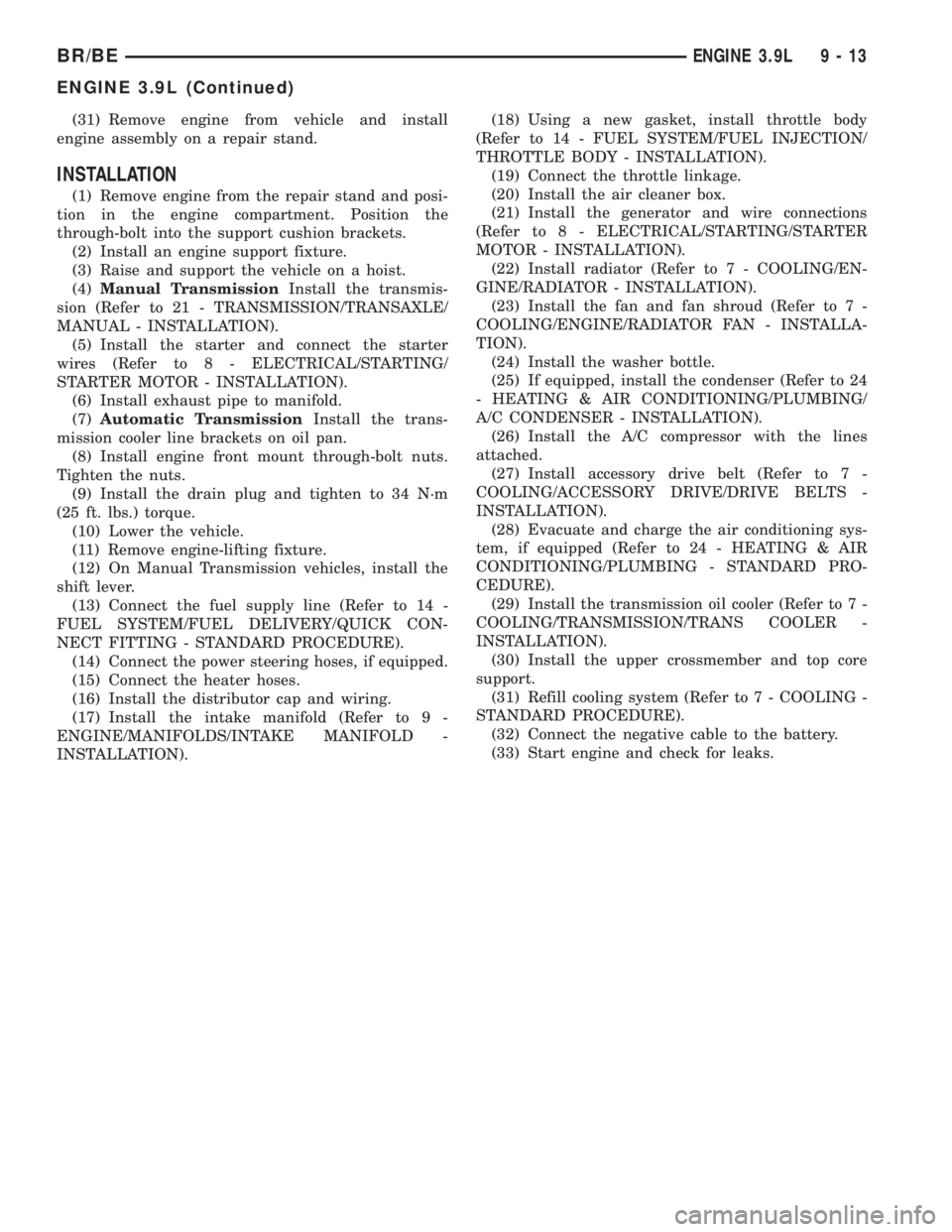
(31) Remove engine from vehicle and install
engine assembly on a repair stand.
INSTALLATION
(1) Remove engine from the repair stand and posi-
tion in the engine compartment. Position the
through-bolt into the support cushion brackets.
(2) Install an engine support fixture.
(3) Raise and support the vehicle on a hoist.
(4)Manual TransmissionInstall the transmis-
sion (Refer to 21 - TRANSMISSION/TRANSAXLE/
MANUAL - INSTALLATION).
(5) Install the starter and connect the starter
wires (Refer to 8 - ELECTRICAL/STARTING/
STARTER MOTOR - INSTALLATION).
(6) Install exhaust pipe to manifold.
(7)Automatic TransmissionInstall the trans-
mission cooler line brackets on oil pan.
(8) Install engine front mount through-bolt nuts.
Tighten the nuts.
(9) Install the drain plug and tighten to 34 N´m
(25 ft. lbs.) torque.
(10) Lower the vehicle.
(11) Remove engine-lifting fixture.
(12) On Manual Transmission vehicles, install the
shift lever.
(13) Connect the fuel supply line (Refer to 14 -
FUEL SYSTEM/FUEL DELIVERY/QUICK CON-
NECT FITTING - STANDARD PROCEDURE).
(14) Connect the power steering hoses, if equipped.
(15) Connect the heater hoses.
(16) Install the distributor cap and wiring.
(17) Install the intake manifold (Refer to 9 -
ENGINE/MANIFOLDS/INTAKE MANIFOLD -
INSTALLATION).(18) Using a new gasket, install throttle body
(Refer to 14 - FUEL SYSTEM/FUEL INJECTION/
THROTTLE BODY - INSTALLATION).
(19) Connect the throttle linkage.
(20) Install the air cleaner box.
(21) Install the generator and wire connections
(Refer to 8 - ELECTRICAL/STARTING/STARTER
MOTOR - INSTALLATION).
(22) Install radiator (Refer to 7 - COOLING/EN-
GINE/RADIATOR - INSTALLATION).
(23) Install the fan and fan shroud (Refer to 7 -
COOLING/ENGINE/RADIATOR FAN - INSTALLA-
TION).
(24) Install the washer bottle.
(25) If equipped, install the condenser (Refer to 24
- HEATING & AIR CONDITIONING/PLUMBING/
A/C CONDENSER - INSTALLATION).
(26) Install the A/C compressor with the lines
attached.
(27) Install accessory drive belt (Refer to 7 -
COOLING/ACCESSORY DRIVE/DRIVE BELTS -
INSTALLATION).
(28) Evacuate and charge the air conditioning sys-
tem, if equipped (Refer to 24 - HEATING & AIR
CONDITIONING/PLUMBING - STANDARD PRO-
CEDURE).
(29) Install the transmission oil cooler (Refer to 7 -
COOLING/TRANSMISSION/TRANS COOLER -
INSTALLATION).
(30) Install the upper crossmember and top core
support.
(31) Refill cooling system (Refer to 7 - COOLING -
STANDARD PROCEDURE).
(32) Connect the negative cable to the battery.
(33) Start engine and check for leaks.
BR/BEENGINE 3.9L 9 - 13
ENGINE 3.9L (Continued)
Page 1165 of 2889
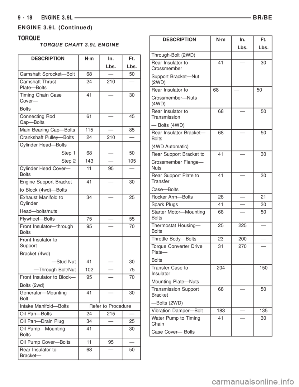
TORQUE
TORQUE CHART 3.9L ENGINE
DESCRIPTION N´m In. Ft.
Lbs. Lbs.
Camshaft SprocketÐBolt 68 Ð 50
Camshaft Thrust
PlateÐBolts24 210 Ð
Timing Chain Case
CoverÐ41 Ð 30
Bolts
Connecting Rod
CapÐBolts61 Ð 45
Main Bearing CapÐBolts 115 Ð 85
Crankshaft PulleyÐBolts 24 210 Ð
Cylinder HeadÐBolts
Step 1 68 Ð 50
Step 2 143 Ð 105
Cylinder Head CoverÐ
Bolts11 95 Ð
Engine Support Bracket 41 Ð 30
to Block (4wd)ÐBolts
Exhaust Manifold to
Cylinder34 Ð 25
HeadÐbolts/nuts
FlywheelÐBolts 75 Ð 55
Front InsulatorÐthrough
Bolts95 Ð 70
Front Insulator to
Support
Bracket (4wd)
ÐStud Nut 41 Ð 30
ÐThrough Bolt/Nut 102 Ð 75
Front Insulator to BlockÐ 95 Ð 70
Bolts (2wd)
GeneratorÐMounting
Bolt41 Ð 30
Intake ManifoldÐBolts Refer to Procedure
Oil PanÐBolts 24 215 Ð
Oil PanÐDrain Plug 34 Ð 25
Oil PumpÐMounting
Bolts41 Ð 30
Oil Pump CoverÐBolts 11 95 Ð
Rear Insulator to
BracketÐ68 Ð 50
DESCRIPTION N´m In. Ft.
Lbs. Lbs.
Through-Bolt (2WD)
Rear Insulator to
Crossmember41 Ð 30
Support BracketÐNut
(2WD)
Rear Insulator to 68 Ð 50
CrossmemberÐNuts
(4WD)
Rear Insulator to
Transmission68 Ð 50
Ð Bolts (4WD)
Rear Insulator BracketÐ
Bolts68 Ð 50
(4WD Automatic)
Rear Support Bracket to 41 Ð 30
Crossmember FlangeÐ
Nuts
Rear Support Plate to
Transfer41 Ð 30
CaseÐBolts
Rocker ArmÐBolts 28 Ð 21
Spark Plugs 41 Ð 30
Starter MotorÐMounting
Bolts68 Ð 50
Thermostat HousingÐ
Bolts25 225 Ð
Throttle BodyÐBolts 23 200 Ð
Torque Converter Drive
PlateÐ31 270 Ð
Bolts
Transfer Case to
Insulator204 Ð 150
Mounting PlateÐNuts
Transmission Support
Bracket68 Ð 50
ÐBolts (2WD)
Vibration DamperÐBolt 183 Ð 135
Water Pump to Timing
Chain41 Ð 30
Case CoverÐ Bolts
9 - 18 ENGINE 3.9LBR/BE
ENGINE 3.9L (Continued)