2001 DODGE RAM Trac-lok friction modifier
[x] Cancel search: Trac-lok friction modifierPage 18 of 2889
DESCRIPTION
A multi-purpose, hypoid gear lubricant which con-
forms to the following specifications should be used.
Mopar Hypoid Gear Lubricant conforms to all of
these specifications.
SAE ratings also apply to multiple grade gear
lubricants. In addition, API classification defines the
lubricants usage.
FRONT AXLE
²The lubricant should have MIL-L-2105C and
API GL 5 quality specifications.
²Lubricant is SAE 75W-140 SYNTHETIC gear
lubricant.
REAR AXLE
²The lubricant should have MIL-L-2105C and
API GL 5 quality specifications.
²Lubricant is a thermally stable SAE 80W-90
gear lubricant.
²Lubricant for axles intended for heavy-duty or
trailer tow use is SAE 75W-140 SYNTHETIC gear
lubricant.
NOTE: Trac-lokYand Vari-lokYequipped axles
require a friction modifier be added to the lubricant.
CAUTION: If axle is submerged in water, lubricant
must be replaced immediately to avoid possible
premature axle failure.
DESCRIPTION - TRANSFER CASE FLUID
Recommended lubricant for the NV231 and NV241
transfer case is MopartATF +4, (MS 9602) Auto-
matic Transmission Fluid.
DESCRIPTION - AUTOMATIC TRANSMISSION
FLUID
NOTE: Refer to the maintenance schedules in this
group for the recommended maintenance (fluid/filter
change) intervals for this transmission.
NOTE: Refer to Service Procedures in this group for
fluid level checking procedures.
MopartATF +4, type 9602, Automatic Transmis-
sion Fluid is the recommended fluid for Daimler-
Chrysler automatic transmissions.
Dexron II fluid IS NOT recommended. Clutch
chatter can result from the use of improper
fluid.MopartATF +4, type 9602, Automatic Transmis-
sion Fluid when new is red in color. The ATF is dyed
red so it can be identified from other fluids used in
the vehicle such as engine oil or antifreeze. The red
color is not permanent and is not an indicator of fluid
condition. As the vehicle is driven, the ATF will begin
to look darker in color and may eventually become
brown.This is normal.A dark brown/black fluid
accompanied with a burnt odor and/or deterioration
in shift quality may indicate fluid deterioration or
transmission component failure.
FLUID ADDITIVES
DaimlerChrysler strongly recommends against the
addition of any fluids to the transmission, other than
those automatic transmission fluids listed above.
Exceptions to this policy are the use of special dyes
to aid in detecting fluid leaks.
Various ªspecialº additives and supplements exist
that claim to improve shift feel and/or quality. These
additives and others also claim to improve converter
clutch operation and inhibit overheating, oxidation,
varnish, and sludge. These claims have not been sup-
ported to the satisfaction of DaimlerChrysler and
these additivesmust not be used.The use of trans-
mission ªsealersº should also be avoided, since they
may adversely affect the integrity of transmission
seals.
OPERATION - AUTOMATIC TRANSMISSION
FLUID
The automatic transmission fluid is selected based
upon several qualities. The fluid must provide a high
level of protection for the internal components by
providing a lubricating film between adjacent metal
components. The fluid must also be thermally stable
so that it can maintain a consistent viscosity through
a large temperature range. If the viscosity stays con-
stant through the temperature range of operation,
transmission operation and shift feel will remain con-
sistent. Transmission fluid must also be a good con-
ductor of heat. The fluid must absorb heat from the
internal transmission components and transfer that
heat to the transmission case.
BR/BELUBRICATION & MAINTENANCE 0 - 5
FLUID TYPES (Continued)
Page 171 of 2889
ASSEMBLY
(1) Install differential side gears and thrust wash-
ers.
(2) Install differential pinion and thrust washers.
(3) Install the pinion shaft.
(4) Align the hole in the pinion shaft with the hole
in the differential case and install the pinion shaft
lock screw.
(5) Lubricate all differential components with
hypoid gear lubricant.
INSTALLATION
(1) Apply a coating of hypoid gear lubricant to the
differential bearings, bearing cups, and threaded
adjusters. A dab of grease can be used to keep the
adjusters in position. Carefully position the assem-
bled differential case in the housing.
(2) Observe the reference marks and install the
differential bearing caps at their original locations
(Fig. 29).
(3) Install bearing cap bolts and tighten the upper
bolts to 14 N´m (10 ft. lbs.). Tighten the lower bolts
finger-tight until the bolt head is seated.
(4) Perform the differential bearing preload and
adjustment procedure.
NOTE: Be sure that all bearing cap bolts are tight-
ened to their final torque of 136 N´m (100 ft.lbs.)
before proceeding.
(5) Install the axle shafts.
(6) Apply a bead of Mopar Silicone Rubber Sealant
or equivalent to the housing cover (Fig. 30).Install the housing cover within 5 minutes
after applying the sealant.
(7) Install the cover and any identification tag.
Tighten the cover bolts to 41 N´m (30 ft. lbs.) torque.
(8) Fill differential with lubricant to bottom of the
fill plug hole. Refer to the Lubricant Specifications
for the quantity and type.
(9) Install the fill hole plug and lower the vehicle.
(10) Trac-lokydifferential equipped vehicles
should be road tested by making 10 to 12 slow figure-
eight turns. This maneuver will pump the lubricant
through the clutch discs to eliminate a possible chat-
ter noise complaint.
DIFFERENTIAL - TRAC-LOK
DIAGNOSIS AND TESTING - TRAC-LOKY
The most common problem is a chatter noise when
turning corners. Before removing a Trac-lokyunit
for repair, drain, flush and refill the axle with the
specified lubricant. A container of Mopar Trac-loky
Lubricant (friction modifier) should be added after
repair service or during a lubricant change.
After changing the lubricant, drive the vehicle and
make 10 to 12 slow, figure-eight turns. This maneu-
ver will pump lubricant through the clutches. This
will correct the condition in most instances. If the
chatter persists, clutch damage could have occurred.
DIFFERENTIAL TEST
The differential can be tested without removing the
differential case by measuring rotating torque. Make
sure brakes are not dragging during this measure-
ment.
(1) Place blocks in front and rear of both front
wheels.
Fig. 29 Bearing Caps & Bolts
1 - REFERENCE MARKS
2 - REFERENCE MARKS
3 - ADJUSTER LOCK
4 - BEARING CAP
Fig. 30 Differential Cover
1 - SEALANT
2 - DIFFERENTIAL COVER
3 - 98 REAR AXLE-91/4BR/BE
DIFFERENTIAL (Continued)
Page 174 of 2889
ASSEMBLY
Clean all components in cleaning solvent. Dry com-
ponents with compressed air. Inspect clutch pack
plates for wear, scoring or damage. Replace both
clutch packs if any one component in either pack is
damaged. Inspect side gears and pinions. Replace
any gear that is worn, cracked, chipped or damaged.
Inspect differential case and pinion shaft. Replace if
worn or damaged.Lubricate each component with gear lubricant
before assembly.
(1) Assemble the clutch discs into packs and
secure disc packs with retaining clips (Fig. 40).
NOTE: New Plates and discs with fiber coating (no
grooves or lines) must be presoaked in Friction
Modifier before assembly. Soak plates and discs for
a minimum of 20 minutes.
(2) Position assembled clutch disc packs on the
side gear hubs.
(3) Install clutch pack and side gear in the ring
gear side of the differential case (Fig. 41).Be sure
clutch pack retaining clips remain in position
and are seated in the case pockets.
(4) Position the differential case on the Holding
Fixture 6965.
(5) Install lubricated Step Plate C-6960-3 in lower
side gear (Fig. 42).
(6) Install the upper side gear and clutch disc pack
(Fig. 42).
(7) Hold assembly in position. Insert Threaded
Adapter C-6960-1 into top side gear.
(8) Install Forcing Screw C-6960-4 and tighten
screw to slightly compress clutch disc.
(9) Place differential pinion gears in position in
side gears and verify that the pinion shaft hole is
aligned.
Fig. 37 Pinion Gear Thrust Washer
1 - THRUST WASHER
2 - FEELER GAUGE
Fig. 38 Pinion Gear
1 - PINION GEARS
2 - TOOL
Fig. 39 Side Gear & Clutch Pack
1 - DIFFERENTIAL CASE
2 - RETAINER
3 - SIDE GEAR AND CLUTCH DISC PACK
BR/BEREAR AXLE - 9 1/4 3 - 101
DIFFERENTIAL - TRAC-LOK (Continued)
Page 203 of 2889

(10) Apply a bead of Mopar Silicone Rubber Seal-
ant or equivalent to the housing cover (Fig. 34).
Install the housing cover within 5 minutes
after applying the sealant.
(11) Install the cover and any identification tag.
Tighten the cover bolts in a criss-cross pattern to 47
N´m (35 ft. lbs.).
(12) Refill the differential with Mopar Hypoid
Gear Lubricant or equivalent to bottom of the fill
plug hole. Refer to the Lubricant Specifications for
correct quantity and type.
(13) Install the fill hole plug and tighten to 34 N´m
(25 ft. lbs.).
(14) Remove support and lower vehicle.
DIFFERENTIAL - TRAC-LOK
DIAGNOSIS AND TESTING - TRAC-LOKY
The most common problem is a chatter noise when
turning corners. Before removing a Trac-lokyunit
for repair, drain, flush and refill the axle with the
specified lubricant. A container of Mopar Trac-loky
Lubricant (friction modifier) should be added after
repair service or during a lubricant change.
After changing the lubricant, drive the vehicle and
make 10 to 12 slow, figure-eight turns. This maneu-
ver will pump lubricant through the clutches. Thiswill correct the condition in most instances. If the
chatter persists, clutch damage could have occurred.
DIFFERENTIAL TEST
The differential can be tested without removing the
differential case by measuring rotating torque. Make
sure brakes are not dragging during this measure-
ment.
(1) Place blocks in front and rear of both front
wheels.
(2) Raise one rear wheel until it is completely off
the ground.
(3) Engine off, transmission in neutral, and park-
ing brake off.
(4) Remove wheel and bolt Special Tool 6790 or
equivalent tool to studs.
(5) Use torque wrench on special tool to rotate
wheel and read rotating torque (Fig. 35).
(6) If rotating torque is less than 22 N´m (30 ft.
lbs.) or more than 271 N´m (200 ft. lbs.) on either
wheel the unit should be serviced.
DISASSEMBLY
(1) Clamp side gear Holding Fixture 6965 in a vise
and position the differential case on the Holding Fix-
ture (Fig. 36).
(2) Remove ring gear if the ring gear is to be
replaced. The Trac-lokydifferential can be serviced
with the ring gear installed.
(3) Remove pinion shaft roll pin.
(4) Remove pinion shaft with a drift and hammer
(Fig. 37).
(5) Install and lubricate Step Plate C-6960-3 (Fig.
38).
Fig. 34 Differential Cover
1 - SEALANT SURFACE
2 - SEALANT
3 - SEALANT THICKNESS
Fig. 35 Trac-lokYTest -Typical
1 - SPECIAL TOOL 6790 WITH BOLT IN CENTER HOLE
2 - TORQUE WRENCH
3 - 130 REAR AXLE - 248RBIBR/BE
DIFFERENTIAL (Continued)
Page 205 of 2889
(8) Install Forcing Screw C-6960-4 and tighten
screw to 122 N´m (90 ft. lbs.) maximum to compress
Belleville springs in clutch packs (Fig. 40).
(9) With a feeler gauge remove thrust washers
from behind the differential pinion gears (Fig. 41).
(10) Insert Turning Bar C-6960-2 into the pinion
shaft hole in the case (Fig. 42).(11) Loosen the Forcing Screw in small increments
until the clutch pack tension is relieved and the dif-
ferential case can be turned using Turning Bar.
(12) Rotate differential case until the pinion gears
can be removed.
(13) Remove pinion gears from differential case.
(14) Remove Forcing Screw, Step Plate and
Threaded Adapter.
(15) Remove top side gear, clutch pack retainer
and clutch pack. Keep plates in correct order during
removal (Fig. 43).
(16) Remove differential case from the Holding
Fixture. Remove side gear, clutch pack retainer and
clutch pack. Keep plates in correct order during
removal.
ASSEMBLY
Clean all components in cleaning solvent. Dry com-
ponents with compressed air. Inspect clutch pack
plates for wear, scoring or damage. Replace both
clutch packs if any one component in either pack is
damaged. Inspect side gears and pinions. Replace
any gear that is worn, cracked, chipped or damaged.
Inspect differential case and pinion shaft. Replace if
worn or damaged.
Lubricate each component with gear lubricant
before assembly.
(1) Assemble the clutch discs into packs and
secure disc packs with retaining clips (Fig. 44).
NOTE: New Plates and discs with fiber coating (no
grooves or lines) must be presoaked in Friction
Modifier before assembly. Soak plates and discs for
a minimum of 20 minutes.
Fig. 40 Compress Belleville Spring
1 - TORQUE WRENCH
2 - TOOL ASSEMBLED
3 - DIFFERENTIAL CASE
Fig. 41 Pinion Gear Thrust Washer
1 - THRUST WASHER
2 - FEELER GAUGE
Fig. 42 Pinion Gear
1 - PINION GEARS
2 - TOOL
3 - 132 REAR AXLE - 248RBIBR/BE
DIFFERENTIAL - TRAC-LOK (Continued)
Page 263 of 2889
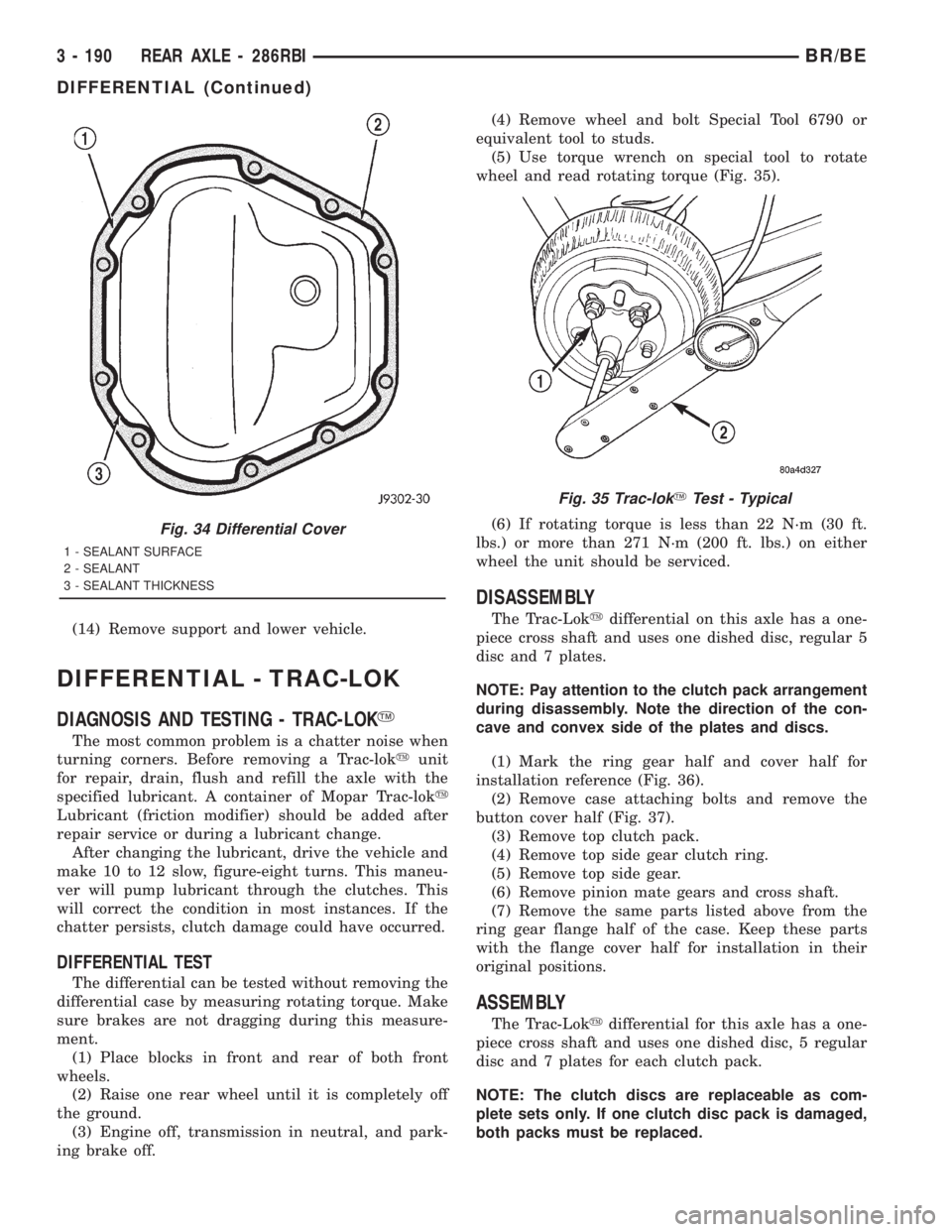
(14) Remove support and lower vehicle.
DIFFERENTIAL - TRAC-LOK
DIAGNOSIS AND TESTING - TRAC-LOKY
The most common problem is a chatter noise when
turning corners. Before removing a Trac-lokyunit
for repair, drain, flush and refill the axle with the
specified lubricant. A container of Mopar Trac-loky
Lubricant (friction modifier) should be added after
repair service or during a lubricant change.
After changing the lubricant, drive the vehicle and
make 10 to 12 slow, figure-eight turns. This maneu-
ver will pump lubricant through the clutches. This
will correct the condition in most instances. If the
chatter persists, clutch damage could have occurred.
DIFFERENTIAL TEST
The differential can be tested without removing the
differential case by measuring rotating torque. Make
sure brakes are not dragging during this measure-
ment.
(1) Place blocks in front and rear of both front
wheels.
(2) Raise one rear wheel until it is completely off
the ground.
(3) Engine off, transmission in neutral, and park-
ing brake off.(4) Remove wheel and bolt Special Tool 6790 or
equivalent tool to studs.
(5) Use torque wrench on special tool to rotate
wheel and read rotating torque (Fig. 35).
(6) If rotating torque is less than 22 N´m (30 ft.
lbs.) or more than 271 N´m (200 ft. lbs.) on either
wheel the unit should be serviced.
DISASSEMBLY
The Trac-Lokydifferential on this axle has a one-
piece cross shaft and uses one dished disc, regular 5
disc and 7 plates.
NOTE: Pay attention to the clutch pack arrangement
during disassembly. Note the direction of the con-
cave and convex side of the plates and discs.
(1) Mark the ring gear half and cover half for
installation reference (Fig. 36).
(2) Remove case attaching bolts and remove the
button cover half (Fig. 37).
(3) Remove top clutch pack.
(4) Remove top side gear clutch ring.
(5) Remove top side gear.
(6) Remove pinion mate gears and cross shaft.
(7) Remove the same parts listed above from the
ring gear flange half of the case. Keep these parts
with the flange cover half for installation in their
original positions.
ASSEMBLY
The Trac-Lokydifferential for this axle has a one-
piece cross shaft and uses one dished disc, 5 regular
disc and 7 plates for each clutch pack.
NOTE: The clutch discs are replaceable as com-
plete sets only. If one clutch disc pack is damaged,
both packs must be replaced.
Fig. 34 Differential Cover
1 - SEALANT SURFACE
2 - SEALANT
3 - SEALANT THICKNESS
Fig. 35 Trac-lokYTest - Typical
3 - 190 REAR AXLE - 286RBIBR/BE
DIFFERENTIAL (Continued)