2001 DODGE RAM fuse box location
[x] Cancel search: fuse box locationPage 431 of 2889
securely to the connector on the end of the antenna
cable being installed into the instrument panel. This
cord will be used to pull or ªfishº the cable back into
position.
(2) Using the cord or twine, pull the antenna cable
through the radio receiver opening from under the
instrument panel.
(3) Install the radio receiver onto the instrument
panel.
(4) Reach through the glove box opening to engage
the antenna cable with the retainer clips on the back
of the instrument panel.
(5) Install the glove box onto the instrument panel.
(6) Untie the cord or twine from the instrument
panel antenna cable connector.
(7) Reach under the passenger side of the instru-
ment panel near the right cowl side inner panel to
reconnect the two halves of the radio antenna coaxial
cable connector. Wrap the connection with a piece of
foam tape.
(8) Engage the coaxial cable connector with the
retainer clip located on the bottom of the heater-A/C
housing.
(9) Reconnect the battery negative cable.
RADIO CHOKE RELAY
DESCRIPTION
Models equipped with the Infinity premium
speaker package have a filter, choke, and speaker
relay unit. The filter, choke, and speaker relay unit is
mounted to the lower instrument panel center brace,
inboard of the Central Timer Module (CTM) and
directly above the 16-way data link connector. The
filter, choke, and speaker relay unit can be accessed
for service without instrument panel disassembly or
removal.
The filter, choke, and speaker relay unit should be
checked if there is no sound output noted from the
speakers. The filter, choke, and speaker relay unit
cannot be repaired or adjusted and, if faulty or dam-
aged, the unit must be replaced.
OPERATION
The filter, choke, and speaker relay unit is used to
control the supply of fused battery current to the
front door speaker-mounted dual amplifiers. The
speaker relay is energized by a fused 12 volt output
from the radio receiver whenever the radio is turned
on. For complete circuit diagrams, refer to the appro-
priate wiring information. The wiring information
includes wiring diagrams, proper wire and connector
repair procedures, details of wire harness routing
and retention, connector pin-out information andlocation views for the various wire harness connec-
tors, splices and grounds.
DIAGNOSIS AND TESTING - RADIO CHOKE
RELAY
The filter, choke and speaker relay is used to
switch power to the individual speaker amplifiers
used with the Infinity premium speaker package.
The choke and relay are serviced only as a unit. If all
of the speakers are inoperative the filter, choke and
speaker relay unit should be considered suspect.
However, before replacement make the following
checks of the filter, choke and speaker relay circuits.
For complete circuit diagrams, refer to the appropri-
ate wiring information. The wiring information
includes wiring diagrams, proper wire and connector
repair procedures, details of wire harness routing
and retention, connector pin-out information and
location views for the various wire harness connec-
tors, splices and grounds.
(1)
Check the fused B(+) fuse in the junction block.
If OK, go to Step 2. If not OK, replace the faulty fuse.
(2) Check for battery voltage at the fused B(+) fuse
in the junction block. If OK, go to Step 3. If not OK,
repair the open fused B(+) circuit to the battery as
required.
(3) Disconnect the instrument panel wire harness
connector from the filter, choke and speaker relay
unit. Check for battery voltage at the fused B(+) cir-
cuit cavity of the instrument panel wire harness con-
nector for the filter, choke and speaker relay unit. If
OK, go to Step 4. If not OK, repair the open fused
B(+) circuit to the junction block fuse as required.
(4) Probe the ground circuit cavity of the instru-
ment panel wire harness connector for the filter,
choke and speaker relay unit. Check for continuity to
a good ground. There should be continuity. If OK, go
to Step 5. If not OK, repair the open ground circuit to
ground as required.
(5) Turn the ignition switch to the On position and
turn the radio on. Check for battery voltage at the
radio 12-volt output circuit cavity of the instrument
panel wire harness connector for the filter, choke and
speaker relay unit. If OK, go to Step 6. If not OK,
repair the open radio 12-volt output circuit to the
radio as required.
(6) Turn the radio and ignition switches to the Off
position. Reconnect the instrument panel wire har-
ness connector to the filter, choke and speaker relay
unit. Check for battery voltage at the amplified
speaker (+) circuit cavity of the instrument panel
wire harness connector for the filter, choke and
speaker relay unit. There should be zero volts. Turn
the ignition and radio switches to the On position.
8A - 8 AUDIOBR/BE
ANTENNA BODY & CABLE (Continued)
Page 433 of 2889
(7) Remove the radio receiver from the instrument
panel. Refer to Audio, Radio for the procedures.
(8) Pull the antenna cable out through the radio
receiver opening in the instrument panel.
(9) Untie the cord or twine from the instrument
panel antenna cable connector, leaving the cord or
twine in place of the cable in the instrument panel.
(10) Remove the antenna cable from the instru-
ment panel.
INSTALLATION
(1) Tie the end of the cord or twine that was used
during instrument panel antenna cable removal
securely to the connector on the end of the antenna
cable being installed into the instrument panel. This
cord will be used to pull or ªfishº the cable back into
position.
(2) Using the cord or twine, pull the antenna cable
through the radio receiver opening from under the
instrument panel.
(3) Install the radio receiver onto the instrument
panel. Refer to Audio, Radio for the procedures.
(4) Reach through the glove box opening to engage
the antenna cable with the retainer clips on the back
of the instrument panel.
(5) Install the glove box onto the instrument panel.
Refer to Body, Instrument Panel for the procedures.
(6) Untie the cord or twine from the instrument
panel antenna cable connector.
(7) Reach under the passenger side of the instru-
ment panel near the right cowl side inner panel to
reconnect the two halves of the radio antenna coaxial
cable connector. Wrap the connection with a piece of
foam tape.
(8) Engage the coaxial cable connector with the
retainer clip located on the bottom of the heater-A/C
housing.
(9) Reconnect the battery negative cable.
RADIO
DESCRIPTION
Available factory-installed radio receivers for this
model include an AM/FM/cassette (RAS sales code),
an AM/FM/cassette/5-band graphic equalizer with CD
changer control feature (RBN sales code), an AM/FM/
CD/3-band graphic equalizer (RBR sales code), or an
AM/FM/CD/cassette/3-band graphic equalizer (RAZ
sales code). The factory-installed RAZ sales code
radio receivers can also communicate on the Chrysler
Collision Detection (CCD) data bus network through
a separate two-way wire harness connector. All facto-
ry-installed receivers are stereo Electronically Tuned
Radios (ETR) and include an electronic digital clock
function.These radio receivers can only be serviced by an
authorized radio repair station. See the latest War-
ranty Policies and Procedures manual for a current
listing of authorized radio repair stations.
All vehicles are equipped with an Ignition-Off
Draw (IOD) fuse that is removed when the vehicle is
shipped from the factory. This fuse feeds various
accessories that require battery current when the
ignition switch is in the Off position, including the
clock. The IOD fuse is removed to prevent battery
discharge during vehicle storage.
When removing or installing the IOD fuse, it is
important that the ignition switch be in the Off posi-
tion. Failure to place the ignition switch in the Off
position can cause the radio display to become scram-
bled when the IOD fuse is removed and replaced.
Removing and replacing the IOD fuse again, with the
ignition switch in the Off position, will correct the
scrambled display condition.
The IOD fuse should be checked if the radio or
clock displays are inoperative. The IOD fuse is
located in the junction block. Refer to the fuse layout
label on the back of the instrument panel fuse access
panel for IOD fuse identification and location.
OPERATION
The radio receiver operates on fused battery cur-
rent that is available only when the ignition switch is
in the On or Accessory positions. The electronic digi-
tal clock function of the radio operates on fused bat-
tery current supplied through the IOD fuse,
regardless of the ignition switch position.
For more information on the features, setting pro-
cedures, and control functions for each of the avail-
able factory-installed radio receivers, see the owner's
manual in the vehicle glove box. For complete circuit
diagrams, refer to the appropriate wiring informa-
tion. The wiring information includes wiring dia-
grams, proper wire and connector repair procedures,
details of wire harness routing and retention, connec-
tor pin-out information and location views for the
various wire harness connectors, splices and grounds.
DIAGNOSIS AND TESTING
DIAGNOSIS AND TESTING - RADIO
If the vehicle is equipped with the optional remote
radio switches located on the steering wheel and the
problem being diagnosed is related to one of the
symptoms listed below, be certain to check the
remote radio switches and circuits. Refer to Audio,
Remote Radio Switch prior to attempting radio diag-
nosis or repair.
²Stations changing with no remote radio switch
input
8A - 10 AUDIOBR/BE
INSTRUMENT PANEL ANTENNA CABLE (Continued)
Page 563 of 2889
The EMIC circuitry operates on battery current
received through a fused B(+) fuse in the Junction
Block (JB) on a non-switched fused B(+) circuit, and
on battery current received through a fused ignition
switch output (st-run) fuse in the JB on a fused igni-
tion switch output (st-run) circuit. This arrangement
allows the EMIC to provide some features regardless
of the ignition switch position, while other features
will operate only with the ignition switch in the Start
or On positions. The EMIC circuitry is grounded
through two separate ground circuits located in one
of the two instrument cluster connectors and take
outs of the instrument panel wire harness. One
ground circuit receives ground through a take out
with an eyelet terminal connector of the instrument
panel wire harness that is secured by a nut to a
ground stud located on the left instrument panel end
bracket, while the other ground circuit receives
ground through a take out with an eyelet terminal
connector of the instrument panel wire harness that
is secured by a nut to a ground stud located on the
back of the instrument panel armature above the
inboard side of the instrument panel steering column
opening.
The EMIC also has a self-diagnostic actuator test
capability, which will test each of the CCD bus mes-
sage-controlled functions of the cluster by lighting
the appropriate indicators and positioning the gauge
needles at several predetermined locations on the
gauge faces in a prescribed sequence. (Refer to 8 -
ELECTRICAL/INSTRUMENT CLUSTER - DIAGNO-
SIS AND TESTING). See the owner's manual in the
vehicle glove box for more information on the fea-
tures, use and operation of the EMIC.
GAUGES
All gauges receive battery current through the
EMIC circuitry when the ignition switch is in the On
or Start positions. With the ignition switch in the Off
position battery current is not supplied to any
gauges, and the EMIC circuitry is programmed to
move all of the gauge needles back to the low end of
their respective scales. Therefore, the gauges do not
accurately indicate any vehicle condition unless the
ignition switch is in the On or Start positions. All of
the EMIC gauges, except the odometer, are air core
magnetic units. Two fixed electromagnetic coils are
located within each gauge. These coils are wrapped
at right angles to each other around a movable per-
manent magnet. The movable magnet is suspended
within the coils on one end of a pivot shaft, while the
gauge needle is attached to the other end of the
shaft. One of the coils has a fixed current flowing
through it to maintain a constant magnetic fieldstrength. Current flow through the second coil
changes, which causes changes in its magnetic field
strength. The current flowing through the second coil
is changed by the EMIC circuitry in response to mes-
sages received over the CCD data bus. The gauge
needle moves as the movable permanent magnet
aligns itself to the changing magnetic fields created
around it by the electromagnets.
The gauges are diagnosed using the EMIC self-di-
agnostic actuator test. (Refer to 8 - ELECTRICAL/
INSTRUMENT CLUSTER - DIAGNOSIS AND
TESTING). Proper testing of the CCD data bus and
the data bus message inputs to the EMIC that con-
trol each gauge require the use of a DRBIIItscan
tool. Refer to the appropriate diagnostic information.
Specific operation details for each gauge may be
found elsewhere in this service manual.
VACUUM-FLUORESCENT DISPLAY
The Vacuum-Fluorescent Display (VFD) module is
soldered to the EMIC circuit board. The display is
active with the ignition switch in the On or Start
positions, and inactive when the ignition switch is in
any other position. The VFD has several display
capabilities including odometer, trip odometer, and
an amber ªCRUISEº indication whenever the
optional speed control system is turned On. The
cruise indicator function of the VFD is automatically
enabled or disabled by the EMIC circuitry based
upon whether the vehicle is equipped with the speed
control option. An odometer/trip odometer switch on
the EMIC circuit board is used to control several of
the display modes. This switch is actuated manually
by depressing the odometer/trip odometer switch
knob that extends through the lower edge of the clus-
ter lens, just right of center. Actuating this switch
momentarily with the ignition switch in the On posi-
tion will toggle the VFD between the odometer and
trip odometer modes. The word ªTRIPº will also
appear in blue-green text when the VFD trip odome-
ter mode is active. Depressing the switch button for
about two seconds while the VFD is in the trip odom-
eter mode will reset the trip odometer value to zero.
Holding this switch depressed while turning the igni-
tion switch from the Off position to the On position
will activate the EMIC self-diagnostic actuator test.
The EMIC will automatically flash the odometer or
trip odometer information on and off if there is a loss
of CCD data bus communication. The VFD will also
display various information used in several diagnos-
tic procedures. Refer to the appropriate diagnostic
information for additional details on this VFD func-
tion.
8J - 4 INSTRUMENT CLUSTERBR/BE
INSTRUMENT CLUSTER (Continued)
Page 600 of 2889
regardless of the ignition switch position. When the
turn signal (multi-function) switch control stalk is
moved up (right turn) or down (left turn), the turn
signal system is activated. When the turn signal sys-
tem is activated, the circuitry of the turn signal
switch and the combination flasher will cause the
selected (right or left) turn signal indicator, front
park/turn signal lamp, and rear tail/stop/turn signal
lamp to flash on and off. With the hazard warning
(multi-function) switch in the On position, the hazard
warning system is activated. When the hazard warn-
ing system is activated, the circuitry of the hazard
warning switch and the combination flasher will
cause both the right side and the left side turn signal
indicators, front park/turn signal lamps, and rear
tail/stop/turn signal lamps to flash on and off.
Refer to the owner's manual in the vehicle glove
box for more information on the features, use and
operation of the turn signal and hazard warning sys-
tem.
DIAGNOSIS AND TESTING - TURN SIGNAL &
HAZARD WARNING SYSTEM
When diagnosing the turn signal and hazard warn-
ing circuits, remember that high generator output
can burn out bulbs rapidly and repeatedly. If this is a
problem on the vehicle being diagnosed, be certain to
diagnose and repair the charging system as required.
If the problem being diagnosed is related to a failure
of the turn signals to automatically cancel following
completion of a turn, inspect the multi-function
switch for a faulty or damaged cancel actuator and
inspect the turn signal cancel cam on the clockspring
for damaged lobes or improper installation. Refer to
the appropriate wiring information. The wiring infor-
mation includes wiring diagrams, proper wire and
connector repair procedures, details of wire harness
routing and retention, connector pin-out information
and location views for the various wire harness con-
nectors, splices and grounds.
WARNING: ON VEHICLES EQUIPPED WITH AIR-
BAGS, DISABLE THE AIRBAG SYSTEM BEFORE
ATTEMPTING ANY STEERING WHEEL, STEERING
COLUMN, OR INSTRUMENT PANEL COMPONENT
DIAGNOSIS OR SERVICE. DISCONNECT AND ISO-
LATE THE BATTERY NEGATIVE (GROUND) CABLE,
THEN WAIT TWO MINUTES FOR THE AIRBAG SYS-
TEM CAPACITOR TO DISCHARGE BEFORE PER-
FORMING FURTHER DIAGNOSIS OR SERVICE. THIS
IS THE ONLY SURE WAY TO DISABLE THE AIRBAG
SYSTEM. FAILURE TO TAKE THE PROPER PRE-
CAUTIONS COULD RESULT IN ACCIDENTAL AIR-
BAG DEPLOYMENT AND POSSIBLE PERSONAL
INJURY.(1) Turn the ignition switch to the On position.
Actuate the turn signal switch or the hazard warning
switch. Observe the turn signal indicator lamp(s) in
the instrument cluster. If the flash rate is very high,
check for a turn signal bulb that is not lit or is very
dimly lit. Repair the circuits to that lamp or replace
the faulty bulb, as required. If the turn signal indi-
cator(s) fail to light, go to Step 2.
(2) Turn the ignition switch to the Off position.
Check the fused ignition switch output (run-acc) fuse
(Fuse 10 - 10 ampere) in the Junction Block (JB) and
the fused B(+) fuse (Fuse4-20ampere) in the
Power Distribution Center (PDC). If OK, go to Step
3. If not OK, repair the shorted circuit or component
as required and replace the faulty fuse(s).
(3) Check for battery voltage at the fused B(+) fuse
(Fuse4-20ampere) in the PDC. If OK, go to Step 4.
If not OK, repair the open fused B(+) circuit between
the PDC and the battery as required.
(4) Turn the ignition switch to the On position.
Check for battery voltage at the fused ignition switch
output (run-acc) fuse (Fuse 10 - 10 ampere) in the
JB. If OK, go to Step 5. If not OK, repair the open
fused ignition switch output (run-acc) circuit between
the JB and the ignition switch as required.
(5) Turn the ignition switch to the Off position.
Disconnect and isolate the battery negative cable.
Remove the combination flasher from the JB and
replace it with a known good unit. Reconnect the bat-
tery negative cable. Test the operation of the turn
signal and hazard warning systems. If OK, discard
the faulty combination flasher. If not OK, remove the
test flasher and go to Step 6.
(6) Turn the ignition switch to the On position.
Check for battery voltage at the fused ignition switch
output (run-acc) circuit cavity in the JB receptacle
for the combination flasher. If OK, go to Step 7. If
not OK, repair the open fused ignition switch output
(run-acc) circuit between the combination flasher and
the fused ignition switch output (run-acc) fuse (Fuse
10 - 10 ampere) in the JB as required.
(7) Turn the ignition switch to the Off position.
Check for battery voltage at the fused B(+) circuit
cavity of the JB receptacle for the combination
flasher. If OK, go to Step 8. If not OK, repair the
open fused B(+) circuit between the combination
flasher and the fused B(+) fuse (Fuse4-20ampere)
in the PDC as required.
(8) Disconnect and isolate the battery negative
cable. Check for continuity between the ground cir-
cuit cavity of the JB receptacle for the combination
flasher and a good ground. There should be continu-
ity. If OK, go to Step 9. If not OK, repair the open
ground circuit to ground (G201) as required.
BR/BELAMPS/LIGHTING - EXTERIOR 8L - 3
LAMPS/LIGHTING - EXTERIOR (Continued)
Page 726 of 2889
activates the washer pump/motor, which dispenses
washer fluid onto the windshield glass through the
washer nozzles.
When the ignition switch is in the Accessory or On
positions, battery current from a fuse in the Junction
Block (JB) is provided through a fused ignition
switch output (run-acc) circuit to the wiper motor
park switch, the wiper relay, and the multi-function
switch. The internal circuitry of the multi-function
switch provides a direct hard wired battery current
output to the low speed or high speed brushes of the
wiper motor when the Lo or Hi switch setting is
selected, which causes the wipers to cycle at the
selected speed. The intermittent wipe, and wipe-af-
ter-wash features of the wiper and washer system
are provided by the electronic intermittent wipe logic
circuit within the Central Timer Module (CTM). In
order to provide the intermittent wipe feature, the
CTM monitors the wiper switch state and the wiper
motor park switch state. In order to provide the
wipe-after-wash feature, the CTM monitors both the
washer switch state and the wiper motor park switch
state. When a Delay position is selected with the
multi-function switch control knob, the CTM logic cir-
cuit responds by calculating the correct delay inter-
val. The CTM then energizes the wiper relay by
pulling the relay control coil to ground. The ener-
gized wiper relay directs battery current through the
normally open contact of the relay back through the
internal circuitry of the multi-function switch to the
low speed brush of the wiper motor. The CTM moni-
tors the wiper motor operation through the wiper
park switch sense circuit, which allows the CTM to
determine the proper timing to begin the next wiper
blade sweep. The normal delay intervals are driver
adjustable from about one-half second to about eigh-
teen seconds.
The high-line and premium CTM also provides a
speed sensitive intermittent wipe feature. By moni-
toring vehicle speed messages received from the Pow-
ertrain Control Module (PCM) over the Chrysler
Collision Detection (CCD) data bus network, the
high-line or premium CTM is able to adjust the delay
intervals to compensate for vehicle speed. Above
about sixteen kilometers-per-hour (ten miles-per-
hour) the delay is driver adjustable from about one-
half second to about eighteen seconds. Below about
sixteen kilometers-per-hour (ten miles-per-hour) the
delay times are doubled by the CTM, from about one
second to about thirty-six seconds.
When the Off position of the multi-function switch
wiper control knob is selected, one of two events is
possible. The event that will occur depends upon the
position of the wiper blades on the windshield at the
moment that the Off position is selected. If the wiper
blades are in the down position on the windshieldwhen the Off position is selected, the park switch
that is integral to the wiper motor is closed to ground
and the wiper motor ceases to operate. If the wiper
blades are not in the down position on the windshield
at the moment the Off position is selected, the park
switch is closed to battery current through a fused
ignition switch output (run-acc) circuit. The park
switch sense circuit directs this battery current to
the low speed brush of the wiper motor through the
normally closed contact of the wiper relay and the
internal Off position circuitry of the multi-function
switch. This causes the wiper motor to continue run-
ning until the wiper blades are in the down position
on the windshield and the park switch is again
closed to ground.
When the Wash position of the multi-function
switch is selected, the Wash position circuitry within
the switch directs battery current to the washer
pump/motor. The CTM monitors the washer switch
state through a washer switch sense input. When the
washer switch is closed with the wiper system turned
Off, the CTM operates the wiper motor through the
wiper relay in the same manner as it does to provide
the Delay mode operation. After the state of the
washer switch changes to open, the CTM monitors
the wiper motor through the wiper park switch sense
circuit, which allows the CTM to monitor the number
of wiper blade sweeps.
Proper testing of the CTM, the PCM, or the CCD
data bus vehicle speed messages requires a DRBIIIt
scan tool. Refer to the appropriate diagnostic infor-
mation. Refer to the owner's manual in the vehicle
glove box for more information on the features and
operation of the wiper and washer system.
DIAGNOSIS AND TESTING - WIPER &
WASHER SYSTEM
WIPER SYSTEM
The diagnosis found here addresses an electrically
inoperative wiper system. If the wiper motor oper-
ates, but the wipers do not move on the windshield,
replace the faulty wiper module. If the wipers oper-
ate, but chatter, lift, or do not clear the glass, clean
and inspect the wiper system components as
required. (Refer to 8 - ELECTRICAL/WIPERS/
WASHERS - INSPECTION) and (Refer to 8 - ELEC-
TRICAL/WIPERS/WASHERS - CLEANING). Refer to
the appropriate wiring information. The wiring infor-
mation includes wiring diagrams, proper wire and
connector repair procedures, details of wire harness
routing and retention, connector pin-out information
and location views for the various wire harness con-
nectors, splices and grounds.
The following tests will help to diagnose the hard
wired components and circuits of the wiper system.
BR/BEWIPERS/WASHERS 8R - 3
WIPERS/WASHERS (Continued)
Page 1136 of 2889
8W-97 POWER DISTRIBUTION
TABLE OF CONTENTS
page page
POWER DISTRIBUTION
DESCRIPTION............................1
OPERATION.............................1
SPECIAL TOOLS..........................2
CIGAR LIGHTER OUTLET
DESCRIPTION............................2
OPERATION.............................2
DIAGNOSIS AND TESTING..................2
CIGAR LIGHTER........................2
REMOVAL...............................3
INSTALLATION............................3
CIRCUIT BREAKER
DESCRIPTION............................4
DIAGNOSIS AND TESTING..................4
CIRCUIT BREAKER......................4
GENERATOR CARTRIDGE FUSE
DESCRIPTION............................4
OPERATION.............................4
REMOVAL...............................4
INSTALLATION............................4
IOD FUSE
DESCRIPTION............................4OPERATION.............................5
REMOVAL...............................5
INSTALLATION............................5
JUNCTION BLOCK
DESCRIPTION............................6
OPERATION.............................6
REMOVAL...............................6
INSTALLATION............................7
POWER DISTRIBUTION CENTER
DESCRIPTION............................7
OPERATION.............................8
REMOVAL...............................8
INSTALLATION............................8
POWER OUTLET
DESCRIPTION............................9
OPERATION.............................10
DIAGNOSIS AND TESTING.................10
POWER OUTLET.......................10
REMOVAL..............................10
INSTALLATION...........................11
POWER DISTRIBUTION
DESCRIPTION
This group covers the various standard and
optional power distribution components used on this
model. The power distribution system for this vehicle
consists of the following components:
²Power Distribution Center (PDC)
²Junction Block (JB).
The power distribution system also incorporates
various types of circuit control and protection fea-
tures, including:
²Automatic resetting circuit breakers
²Blade-type fuses
²Cartridge fuses
²Circuit splice blocks
²Flashers
²Relays.
Following are general descriptions of the major
components in the power distribution system. See the
owner's manual in the vehicle glove box for more
information on the features and use of all of thepower distribution system components. Refer to the
index in this service manual for the location of com-
plete circuit diagrams for the various power distribu-
tion system components.
OPERATION
The power distribution system for this vehicle is
designed to provide safe, reliable, and centralized dis-
tribution points for the electrical current required to
operate all of the many standard and optional facto-
ry-installed electrical and electronic powertrain,
chassis, safety, security, comfort and convenience sys-
tems. At the same time, the power distribution sys-
tem was designed to provide ready access to these
electrical distribution points for the vehicle techni-
cian to use when conducting diagnosis and repair of
faulty circuits. The power distribution system can
also prove useful for the sourcing of additional elec-
trical circuits that may be required to provide the
electrical current needed to operate many accessories
that the vehicle owner may choose to have installed
in the aftermarket.
BR/BE8W-97 POWER DISTRIBUTION 8W - 97 - 1
Page 2678 of 2889
hook formations on the lower edge of the glove box
door are engaged with and pivot on three hinge pins
integral to the lower edge of the instrument panel
support structure. The glove box door also serves as
the passenger side knee blocker. A honeycomb struc-
ture between the inner and outer glove box door pan-
els helps to absorb the impact load and distribute it
to the instrument panel structure.
²Steering Column Opening Cover- The steer-
ing column opening cover serves as the driver side
knee blocker. This molded plastic cover has an inte-
gral ribbed plastic liner concealed behind it, for
increased strength and integrity. The steering column
opening cover transfers impact loads to the instru-
ment panel structural support.
²Top Cover- The instrument panel top cover or
base trim is the molded, grained, and color impreg-
nated plastic outer skin of the instrument panel
structural support.
Hard wired circuitry connects the electrical compo-
nents on the instrument panel to each other through
the electrical system of the vehicle. These hard wired
circuits are integral to several wire harnesses, which
are routed throughout the vehicle and retained by
many different methods. These circuits may be con-
nected to each other, to the vehicle electrical system
and to the instrument panel components through the
use of a combination of soldered splices, splice block
connectors and many different types of wire harness
terminal connectors and insulators. Refer to the
appropriate wiring information. The wiring informa-
tion includes complete circuit diagrams, proper wire
and connector repair procedures, further details on
wire harness routing and retention, as well as pin-
out and location views for the various wire harness
connectors, splices, and grounds.
OPERATION
The instrument panel serves as the command cen-
ter of the vehicle, which necessarily makes it a very
complex unit. The instrument panel is designed to
house the controls and monitors for standard and
optional powertrains, climate control systems, audio
systems, safety systems, and many other comfort or
convenience items. When the components of the
instrument panel structural support are properly
assembled and secured in the vehicle they provide
superior instrument panel stiffness and integrity to
help reduce buzzes, squeaks, and rattles. This type of
construction also provides improved energy absorp-
tion which, in conjunction with the dual airbags and
seat belts, helps to improve occupant protection.
The instrument panel is also designed so that all of
the various controls can be safely reached and the
monitors can be easily viewed by the vehicle operator
when driving, while still allowing relative ease ofaccess to each of these items for service. Modular
instrument panel construction allows all of the
gauges and controls to be serviced from the front of
the panel. In addition, most of the instrument panel
electrical components can be accessed without com-
plete instrument panel removal. However, if neces-
sary, the instrument panel can be removed from the
vehicle as an assembly.
The steering column opening cover with its inte-
gral knee blocker located on the driver side of the
instrument panel works in conjunction with the air-
bag system in a frontal vehicle impact to keep the
driver properly positioned for an airbag deployment.
In addition, removal of this component provides
access to the steering column mounts, the steering
column wiring, the Junction Block (JB) (removal of a
snap-fit fuse access panel on the left end of the
instrument panel allows access to the fuses and cir-
cuit breakers), the Central Timer Module (CTM), the
Infinity speaker filter choke and relay unit, much of
the instrument panel wiring, and the gear selector
indicator cable (automatic transmission).
In a frontal collision, the glove box door on the pas-
senger side of the instrument panel provides the
same function for the front seat passenger as the
knee blocker does for the driver. The glove box door
also incorporates a recessed latch handle. Removal of
the glove box provides access to the passenger airbag,
the glove box lamp and switch, the radio antenna
coaxial cable, the heating and air conditioning vac-
uum harness connector, and additional instrument
panel wiring.
Removal of the instrument panel cluster bezel
allows access to the headlamp switch, instrument
cluster, radio, passenger airbag on-off switch, heated
seat switches (if equipped), and the heating and air
conditioning control. Removal of the instrument clus-
ter allows access to the cluster illumination and indi-
cator bulbs, and more of the instrument panel
wiring. Complete instrument panel removal is
required for service of most components internal to
the heating and air conditioning system housing,
including the heater core and the evaporator.
See the owner's manual in the vehicle glove box for
more information on the features, use and operation
of all of the components and systems mounted on or
in the instrument panel.
BR/BEINSTRUMENT PANEL SYSTEM 23 - 105
INSTRUMENT PANEL SYSTEM (Continued)
Page 2747 of 2889
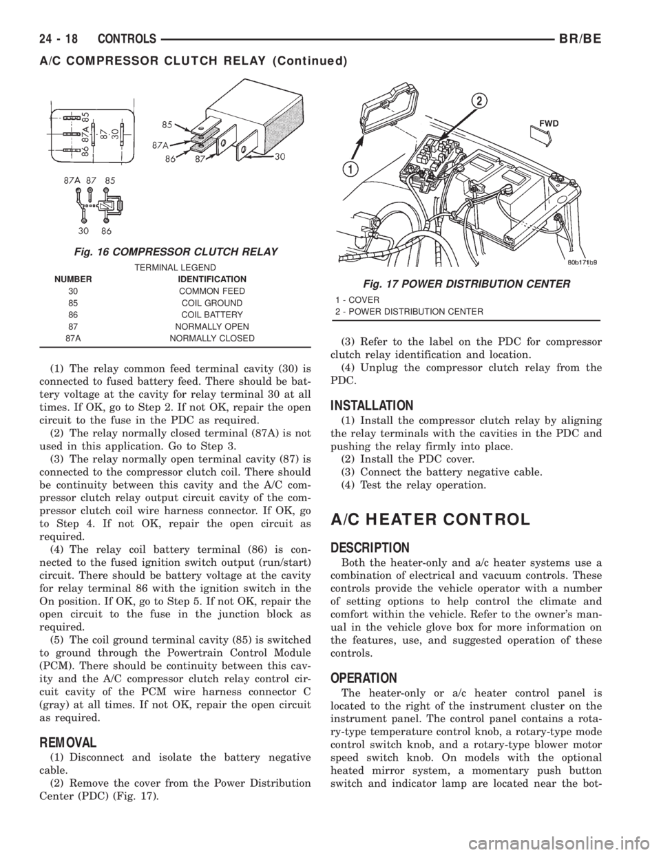
(1) The relay common feed terminal cavity (30) is
connected to fused battery feed. There should be bat-
tery voltage at the cavity for relay terminal 30 at all
times. If OK, go to Step 2. If not OK, repair the open
circuit to the fuse in the PDC as required.
(2) The relay normally closed terminal (87A) is not
used in this application. Go to Step 3.
(3) The relay normally open terminal cavity (87) is
connected to the compressor clutch coil. There should
be continuity between this cavity and the A/C com-
pressor clutch relay output circuit cavity of the com-
pressor clutch coil wire harness connector. If OK, go
to Step 4. If not OK, repair the open circuit as
required.
(4) The relay coil battery terminal (86) is con-
nected to the fused ignition switch output (run/start)
circuit. There should be battery voltage at the cavity
for relay terminal 86 with the ignition switch in the
On position. If OK, go to Step 5. If not OK, repair the
open circuit to the fuse in the junction block as
required.
(5) The coil ground terminal cavity (85) is switched
to ground through the Powertrain Control Module
(PCM). There should be continuity between this cav-
ity and the A/C compressor clutch relay control cir-
cuit cavity of the PCM wire harness connector C
(gray) at all times. If not OK, repair the open circuit
as required.
REMOVAL
(1) Disconnect and isolate the battery negative
cable.
(2) Remove the cover from the Power Distribution
Center (PDC) (Fig. 17).(3) Refer to the label on the PDC for compressor
clutch relay identification and location.
(4) Unplug the compressor clutch relay from the
PDC.
INSTALLATION
(1) Install the compressor clutch relay by aligning
the relay terminals with the cavities in the PDC and
pushing the relay firmly into place.
(2) Install the PDC cover.
(3) Connect the battery negative cable.
(4) Test the relay operation.
A/C HEATER CONTROL
DESCRIPTION
Both the heater-only and a/c heater systems use a
combination of electrical and vacuum controls. These
controls provide the vehicle operator with a number
of setting options to help control the climate and
comfort within the vehicle. Refer to the owner's man-
ual in the vehicle glove box for more information on
the features, use, and suggested operation of these
controls.
OPERATION
The heater-only or a/c heater control panel is
located to the right of the instrument cluster on the
instrument panel. The control panel contains a rota-
ry-type temperature control knob, a rotary-type mode
control switch knob, and a rotary-type blower motor
speed switch knob. On models with the optional
heated mirror system, a momentary push button
switch and indicator lamp are located near the bot-
Fig. 16 COMPRESSOR CLUTCH RELAY
TERMINAL LEGEND
NUMBER IDENTIFICATION
30 COMMON FEED
85 COIL GROUND
86 COIL BATTERY
87 NORMALLY OPEN
87A NORMALLY CLOSED
Fig. 17 POWER DISTRIBUTION CENTER
1 - COVER
2 - POWER DISTRIBUTION CENTER
24 - 18 CONTROLSBR/BE
A/C COMPRESSOR CLUTCH RELAY (Continued)