2001 DODGE RAM harness
[x] Cancel search: harnessPage 102 of 2889
(8) Insert axle shaft into the tube and engage
splined end of the shaft with the shift collar.
(9) Install vacuum shift motor housing.
AXLE SHAFT SEALS
REMOVAL
(1) Remove hub bearings and axle shafts.
(2) Remove axle shaft seal from the differential
housing with a long drift or punch.Be careful not
to damage housing.
(3) Clean the inside perimeter of the differential
housing with fine crocus cloth.
INSTALLATION
(1) Apply a light film of oil to the inside lip of the
new axle shaft seal.
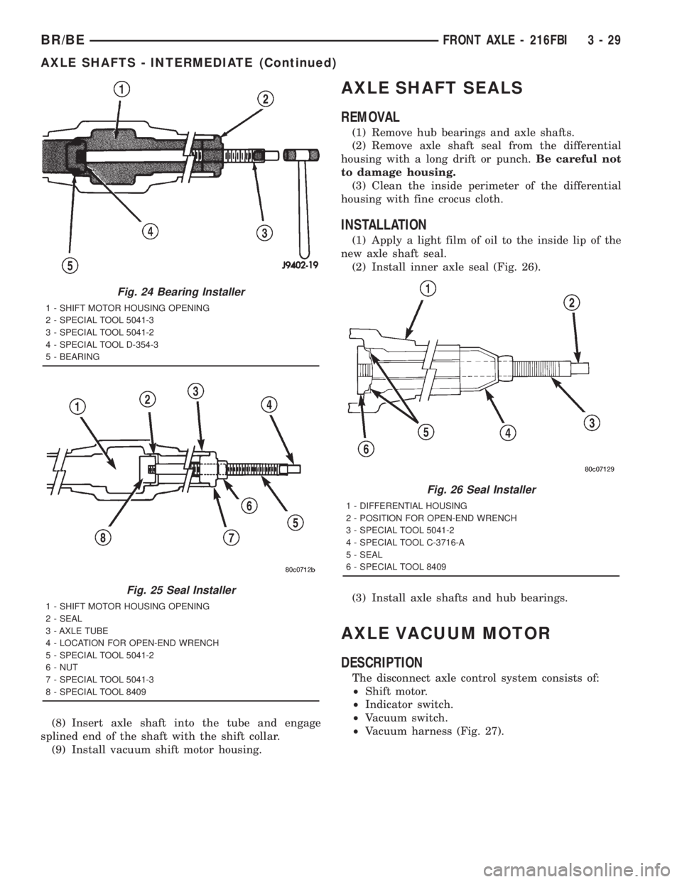
(2) Install inner axle seal (Fig. 26).
(3) Install axle shafts and hub bearings.
AXLE VACUUM MOTOR
DESCRIPTION
The disconnect axle control system consists of:
²Shift motor.
²Indicator switch.
²Vacuum switch.
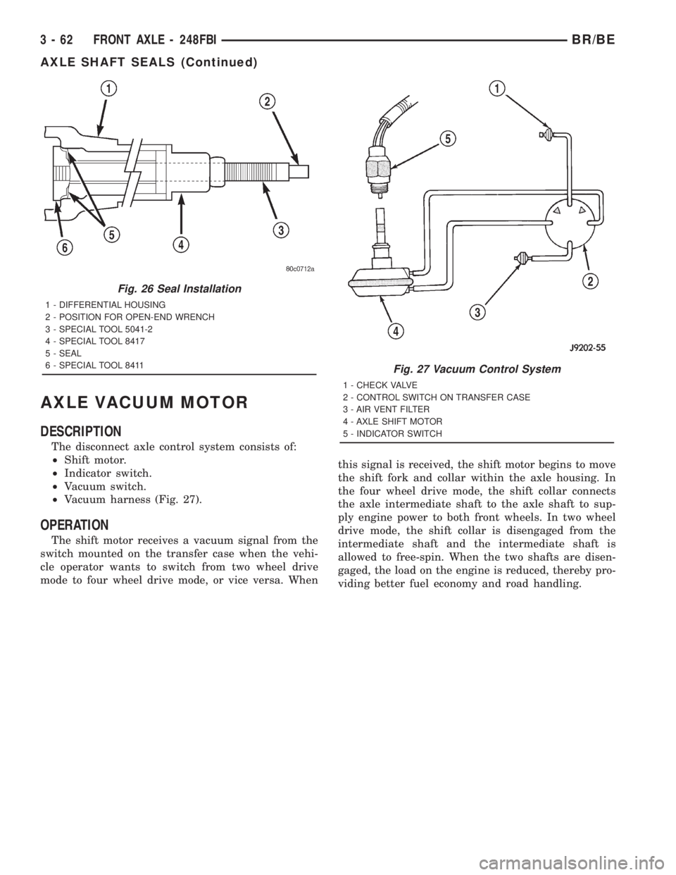
²Vacuum harness (Fig. 27).
Fig. 24 Bearing Installer
1 - SHIFT MOTOR HOUSING OPENING
2 - SPECIAL TOOL 5041-3
3 - SPECIAL TOOL 5041-2
4 - SPECIAL TOOL D-354-3
5 - BEARING
Fig. 25 Seal Installer
1 - SHIFT MOTOR HOUSING OPENING
2 - SEAL
3 - AXLE TUBE
4 - LOCATION FOR OPEN-END WRENCH
5 - SPECIAL TOOL 5041-2
6 - NUT
7 - SPECIAL TOOL 5041-3
8 - SPECIAL TOOL 8409
Fig. 26 Seal Installer
1 - DIFFERENTIAL HOUSING
2 - POSITION FOR OPEN-END WRENCH
3 - SPECIAL TOOL 5041-2
4 - SPECIAL TOOL C-3716-A
5 - SEAL
6 - SPECIAL TOOL 8409
BR/BEFRONT AXLE - 216FBI 3 - 29
AXLE SHAFTS - INTERMEDIATE (Continued)
Page 106 of 2889
REMOVAL
(1) Disconnect the vacuum and wiring connector
from the shift housing.
(2) Remove indicator switch.
(3) Remove shift motor housing cover, gasket and
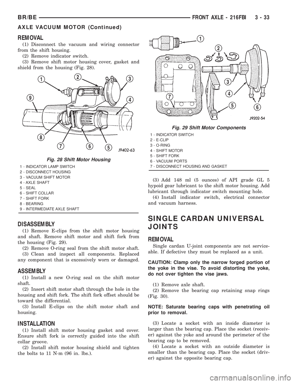
shield from the housing (Fig. 28).
DISASSEMBLY
(1) Remove E-clips from the shift motor housing
and shaft. Remove shift motor and shift fork from
the housing (Fig. 29).
(2) Remove O-ring seal from the shift motor shaft.
(3) Clean and inspect all components. Replaced
any component that is excessively worn or damaged.
ASSEMBLY
(1) Install a new O-ring seal on the shift motor
shaft.
(2) Insert shift motor shaft through the hole in the
housing and shift fork. The shift fork offset should be
toward the differential.
(3) Install E-clips on the shift motor shaft and
housing.
INSTALLATION
(1) Install shift motor housing gasket and cover.
Ensure shift fork is correctly guided into the shift
collar groove.
(2) Install shift motor housing shield and tighten
the bolts to 11 N´m (96 in. lbs.).(3) Add 148 ml (5 ounces) of API grade GL 5
hypoid gear lubricant to the shift motor housing. Add
lubricant through indicator switch mounting hole.
(4) Install indicator switch, electrical connector
and vacuum harness.
SINGLE CARDAN UNIVERSAL
JOINTS
REMOVAL
Single cardan U-joint components are not service-
able. If defective they must be replaced as a unit.
CAUTION: Clamp only the narrow forged portion of
the yoke in the vise. To avoid distorting the yoke,
do not over tighten the vise jaws.
(1) Remove axle shaft.
(2) Remove the bearing cap retaining snap rings
(Fig. 30).
NOTE: Saturate bearing caps with penetrating oil
prior to removal.
(3) Locate a socket with an inside diameter is
larger than the bearing cap. Place the socket (receiv-
er) against the yoke and around the perimeter of the
bearing cap to be removed.
(4) Locate a socket with an outside diameter is
smaller than the bearing cap. Place the socket (driv-
er) against the opposite bearing cap.
Fig. 28 Shift Motor Housing
1 - INDICATOR LAMP SWITCH
2 - DISCONNECT HOUSING
3 - VACUUM SHIFT MOTOR
4 - AXLE SHAFT
5 - SEAL
6 - SHIFT COLLAR
7 - SHIFT FORK
8 - BEARING
9 - INTERMEDIATE AXLE SHAFT
Fig. 29 Shift Motor Components
1 - INDICATOR SWITCH
2 - E-CLIP
3 - O-RING
4 - SHIFT MOTOR
5 - SHIFT FORK
6 - VACUUM PORTS
7 - DISCONNECT HOUSING AND GASKET
BR/BEFRONT AXLE - 216FBI 3 - 33
AXLE VACUUM MOTOR (Continued)
Page 135 of 2889
AXLE VACUUM MOTOR
DESCRIPTION
The disconnect axle control system consists of:
²Shift motor.
²Indicator switch.
²Vacuum switch.
²Vacuum harness (Fig. 27).
OPERATION
The shift motor receives a vacuum signal from the
switch mounted on the transfer case when the vehi-
cle operator wants to switch from two wheel drive
mode to four wheel drive mode, or vice versa. Whenthis signal is received, the shift motor begins to move
the shift fork and collar within the axle housing. In
the four wheel drive mode, the shift collar connects
the axle intermediate shaft to the axle shaft to sup-
ply engine power to both front wheels. In two wheel
drive mode, the shift collar is disengaged from the
intermediate shaft and the intermediate shaft is
allowed to free-spin. When the two shafts are disen-
gaged, the load on the engine is reduced, thereby pro-
viding better fuel economy and road handling.
Fig. 26 Seal Installation
1 - DIFFERENTIAL HOUSING
2 - POSITION FOR OPEN-END WRENCH
3 - SPECIAL TOOL 5041-2
4 - SPECIAL TOOL 8417
5 - SEAL
6 - SPECIAL TOOL 8411
Fig. 27 Vacuum Control System
1 - CHECK VALVE
2 - CONTROL SWITCH ON TRANSFER CASE
3 - AIR VENT FILTER
4 - AXLE SHIFT MOTOR
5 - INDICATOR SWITCH
3 - 62 FRONT AXLE - 248FBIBR/BE
AXLE SHAFT SEALS (Continued)
Page 138 of 2889
REMOVAL
(1) Disconnect the vacuum and wiring connector
from the shift housing.
(2) Remove indicator switch.
(3) Remove shift motor housing cover, gasket and
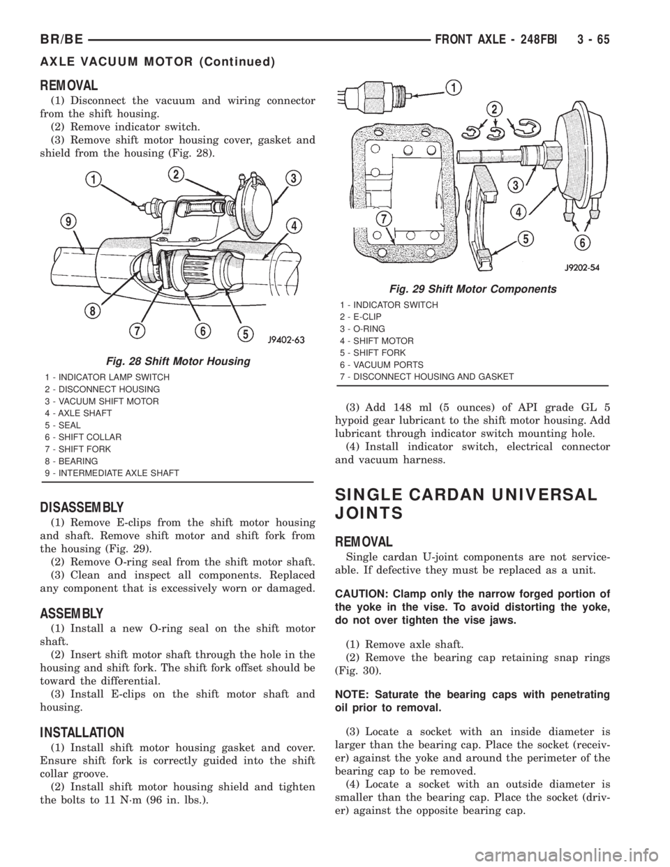
shield from the housing (Fig. 28).
DISASSEMBLY
(1) Remove E-clips from the shift motor housing
and shaft. Remove shift motor and shift fork from
the housing (Fig. 29).
(2) Remove O-ring seal from the shift motor shaft.
(3) Clean and inspect all components. Replaced
any component that is excessively worn or damaged.
ASSEMBLY
(1) Install a new O-ring seal on the shift motor
shaft.
(2) Insert shift motor shaft through the hole in the
housing and shift fork. The shift fork offset should be
toward the differential.
(3) Install E-clips on the shift motor shaft and
housing.
INSTALLATION
(1) Install shift motor housing gasket and cover.
Ensure shift fork is correctly guided into the shift
collar groove.
(2) Install shift motor housing shield and tighten
the bolts to 11 N´m (96 in. lbs.).(3) Add 148 ml (5 ounces) of API grade GL 5
hypoid gear lubricant to the shift motor housing. Add
lubricant through indicator switch mounting hole.
(4) Install indicator switch, electrical connector
and vacuum harness.
SINGLE CARDAN UNIVERSAL
JOINTS
REMOVAL
Single cardan U-joint components are not service-
able. If defective they must be replaced as a unit.
CAUTION: Clamp only the narrow forged portion of
the yoke in the vise. To avoid distorting the yoke,
do not over tighten the vise jaws.
(1) Remove axle shaft.
(2) Remove the bearing cap retaining snap rings
(Fig. 30).
NOTE: Saturate the bearing caps with penetrating
oil prior to removal.
(3) Locate a socket with an inside diameter is
larger than the bearing cap. Place the socket (receiv-
er) against the yoke and around the perimeter of the
bearing cap to be removed.
(4) Locate a socket with an outside diameter is
smaller than the bearing cap. Place the socket (driv-
er) against the opposite bearing cap.
Fig. 28 Shift Motor Housing
1 - INDICATOR LAMP SWITCH
2 - DISCONNECT HOUSING
3 - VACUUM SHIFT MOTOR
4 - AXLE SHAFT
5 - SEAL
6 - SHIFT COLLAR
7 - SHIFT FORK
8 - BEARING
9 - INTERMEDIATE AXLE SHAFT
Fig. 29 Shift Motor Components
1 - INDICATOR SWITCH
2 - E-CLIP
3 - O-RING
4 - SHIFT MOTOR
5 - SHIFT FORK
6 - VACUUM PORTS
7 - DISCONNECT HOUSING AND GASKET
BR/BEFRONT AXLE - 248FBI 3 - 65
AXLE VACUUM MOTOR (Continued)
Page 150 of 2889
REAR AXLE-91/4
TABLE OF CONTENTS
page page
REAR AXLE-91/4
DESCRIPTION...........................77
OPERATION.............................77
DIAGNOSIS AND TESTING.................80
AXLE................................80
REMOVAL..............................83
INSTALLATION...........................84
ADJUSTMENTS..........................84
SPECIFICATIONS........................90
SPECIAL TOOLS.........................90
AXLE SHAFTS
REMOVAL..............................93
INSTALLATION...........................93
AXLE SHAFT SEALS
REMOVAL..............................94
INSTALLATION...........................94
AXLE BEARINGS
REMOVAL..............................94
INSTALLATION...........................95PINION SEAL
REMOVAL..............................95
INSTALLATION...........................95
DIFFERENTIAL
REMOVAL..............................96
DISASSEMBLY...........................97
ASSEMBLY.............................98
INSTALLATION...........................98
DIFFERENTIAL - TRAC-LOK
DIAGNOSIS AND TESTING.................98
TRAC-LOK............................98
DISASSEMBLY...........................99
ASSEMBLY............................101
DIFFERENTIAL CASE BEARINGS
REMOVAL.............................103
INSTALLATION..........................103
PINION GEAR/RING GEAR/TONE RING
REMOVAL.............................103
INSTALLATION..........................105
REAR AXLE-91/4
DESCRIPTION
The 9 1/4 Inch axle housings consist of a cast iron
center section with axle tubes extending from either
side. The tubes are pressed into and welded to the
differential housing to form a one-piece axle housing
(Fig. 1).
The axles have a vent hose to relieve internal pres-
sure caused by lubricant vaporization and internal
expansion.
The axles are equipped with semi-floating axle
shafts, meaning vehicle loads are supported by the
axle shaft and bearings. The axle shafts are retained
by C-locks in the differential side gears.
The removable, stamped steel cover provides a
means for inspection and service without removing
the complete axle from the vehicle.
The axle has a date tag and a gear ratio tag. The
tags are attached to the differential housing by a
cover bolt.
The rear wheel anti-lock (RWAL) brake speed sen-
sor is attached to the top, forward exterior of the dif-
ferential housing. A seal is located between the
sensor and the wire harness connector. The seal must
be in place when the wire connector is connected to
the sensor. The RWAL brake exciter ring is press-fit-ted onto the differential case against the ring gear
flange.
The differential case is a one-piece design. The dif-
ferential pinion shaft is retained with a screw. Differ-
ential bearing preload and ring gear backlash are set
and maintained by threaded adjusters at the outside
of the differential housing. Pinion bearing preload is
set and maintained by the use of a collapsible spacer.
Axles equipped with a Trac-Lokydifferential are
optional. A differential has a one-piece differential
case, and the same internal components as a stan-
dard differential, plus two clutch disc packs.
AXLE IDENTIFICATION
The axle differential cover can be used for identifi-
cation of the axle (Fig. 2). A ratio tag is attached to
the top of the differential cover.
OPERATION
The axle receives power from the transmission/
transfer case through the rear propeller shaft. The
rear propeller shaft is connected to the drive pinion
which rotates the differential through the gear mesh
with the ring gear bolted to the differential case. The
engine power is transmitted to the axle shafts
through the differential pinions and side gears. The
side gears are splined to the axle shafts.
BR/BEREAR AXLE - 9 1/4 3 - 77
Page 182 of 2889

REAR AXLE - 248RBI
TABLE OF CONTENTS
page page
REAR AXLE - 248RBI
DESCRIPTION..........................109
OPERATION............................109
DIAGNOSIS AND TESTING.................111
AXLE...............................111
REMOVAL.............................113
INSTALLATION..........................114
ADJUSTMENTS.........................114
SPECIFICATIONS........................122
SPECIAL TOOLS........................122
AXLE SHAFTS
REMOVAL.............................125
INSTALLATION..........................125
AXLE BEARINGS
REMOVAL.............................125
INSTALLATION..........................125
PINION SEAL
REMOVAL.............................125INSTALLATION..........................125
DIFFERENTIAL
REMOVAL.............................127
DISASSEMBLY..........................128
ASSEMBLY............................128
INSTALLATION..........................129
DIFFERENTIAL - TRAC-LOK
DIAGNOSIS AND TESTING................130
TRAC-LOK...........................130
DISASSEMBLY..........................130
ASSEMBLY............................132
DIFFERENTIAL CASE BEARINGS
REMOVAL.............................134
INSTALLATION..........................134
PINION GEAR/RING GEAR/TONE RING
REMOVAL.............................135
INSTALLATION..........................137
REAR AXLE - 248RBI
DESCRIPTION
The Rear Beam-design Iron (RBI) axle housings
consist of an iron center casting (differential housing)
with axle shaft tubes extending from either side. The
tubes are pressed in to form a one-piece axle housing.
The integral type housing, hypoid gear design has
the centerline of the pinion set below the centerline
of the ring gear.
The axles are equipped with full-floating axle
shafts, meaning that loads are supported by the axle
housing tubes. The full-float axle shafts are retained
by bolts attached to the hub. The hub rides on two
bearings at the outboard end of the axle tube. The
axle shafts can be removed without disturbing or
removing the wheel bearings. The wheel bearings are
opposed tapered roller bearings and are contained in
the hub assembly.
The removable, stamped steel cover provides a
means for inspection and service without removing
the complete axle from the vehicle. A small, stamped
metal axle gear ratio identification tag is attached to
the housing cover via one of the cover bolts. This tag
also identifies the number of ring and pinion teeth.
The rear wheel anti-lock (RWAL) brake speed sen-
sor is attached to the top, forward exterior of the dif-
ferential housing. A seal is located between the
sensor and the wire harness connector. The seal mustbe in place when the wire connector is connected to
the sensor. The RWAL brake exciter ring is press-fit-
ted onto the differential case against the ring gear
flange.
The differential case for the standard differentials
and the Trac-lokydifferential are a one-piece design.
The differential pinion mate shaft is retained with a
roll pin. Differential bearing preload and ring gear
backlash are adjusted by the use of shims located
between the differential bearing cones and case. Pin-
ion bearing preload is set and maintained by the use
of a solid shims.
OPERATION
STANDARD DIFFERENTIAL
The axle receives power from the transmission/
transfer case through the rear propeller shaft. The
rear propeller shaft is connected to the pinion gear
which rotates the differential through the gear mesh
with the ring gear bolted to the differential case. The
engine power is transmitted to the axle shafts
through the pinion mate and side gears. The side
gears are splined to the axle shafts.
During straight-ahead driving, the differential pin-
ion gears do not rotate on the pinion mate shaft. This
occurs because input torque applied to the gears is
divided and distributed equally between the two side
BR/BEREAR AXLE - 248RBI 3 - 109
Page 213 of 2889

REAR AXLE - 267RBI
TABLE OF CONTENTS
page page
REAR AXLE - 267RBI
DESCRIPTION..........................140
OPERATION............................140
DIAGNOSIS AND TESTING................142
AXLE...............................142
REMOVAL.............................144
INSTALLATION..........................145
ADJUSTMENTS.........................145
SPECIFICATIONS........................153
SPECIAL TOOLS........................153
AXLE SHAFTS
REMOVAL.............................156
INSTALLATION..........................156
AXLE BEARINGS
REMOVAL.............................156
INSTALLATION..........................156
PINION SEAL
REMOVAL.............................156INSTALLATION..........................157
DIFFERENTIAL
REMOVAL.............................158
DISASSEMBLY..........................158
ASSEMBLY............................159
INSTALLATION..........................159
DIFFERENTIAL - POWR-LOK
DIAGNOSIS AND TESTING................161
POWR-LOK .........................161
DISASSEMBLY..........................161
ASSEMBLY............................163
DIFFERENTIAL CASE BEARINGS
REMOVAL.............................164
INSTALLATION..........................164
PINION GEAR/RING GEAR/TONE RING
REMOVAL.............................165
INSTALLATION..........................166
REAR AXLE - 267RBI
DESCRIPTION
The Rear Beam-design Iron (RBI) axle housings
consist of an iron center casting (differential housing)
with axle shaft tubes extending from either side. The
tubes are pressed in to form a one-piece axle housing.
The integral type housing, hypoid gear design has
the centerline of the pinion set below the centerline
of the ring gear.
The axles are equipped with full-floating axle
shafts, meaning that loads are supported by the axle
housing tubes. The full-float axle shafts are retained
by bolts attached to the hub. The hub rides on two
bearings at the outboard end of the axle tube. The
axle shafts can be removed without disturbing or
removing the wheel bearings. The wheel bearings are
opposed tapered roller bearings and are contained in
the hub assembly.
The removable, stamped steel cover provides a
means for inspection and service without removing
the complete axle from the vehicle. A small, stamped
metal axle gear ratio identification tag is attached to
the housing cover via one of the cover bolts. This tag
also identifies the number of ring and pinion teeth.
The rear wheel anti-lock (RWAL) brake speed sen-
sor is attached to the top, forward exterior of the dif-
ferential housing. A seal is located between the
sensor and the wire harness connector. The seal mustbe in place when the wire connector is connected to
the sensor. The RWAL brake exciter ring is press-fit-
ted onto the differential case against the ring gear
flange.
The differential case for the standard differential is
a one-piece design. The differential pinion mate shaft
is retained with a roll pin. Differential bearing pre-
load and ring gear backlash are adjusted by the use
of shims located between the differential bearing
cones and case. Pinion bearing preload is set and
maintained by the use of a solid shims.
Axles equipped with a Powr-Lokydifferential are
optional. A Powr-lokydifferential has a two-piece dif-
ferential case. A Powr-lokydifferential contains four
pinion gears and a two-piece pinion mate cross shaft
to provide increased torque to the non-slipping wheel
through a ramping motion in addition to the stan-
dard Trac-lokycomponents.
OPERATION
STANDARD DIFFERENTIAL
The axle receives power from the transmission/
transfer case through the rear propeller shaft. The
rear propeller shaft is connected to the pinion gear
which rotates the differential through the gear mesh
with the ring gear bolted to the differential case. The
engine power is transmitted to the axle shafts
3 - 140 REAR AXLE - 267RBIBR/BE
Page 242 of 2889

REAR AXLE - 286RBI
TABLE OF CONTENTS
page page
REAR AXLE - 286RBI
DESCRIPTION..........................169
OPERATION............................169
DIAGNOSIS AND TESTING................171
AXLE...............................171
REMOVAL.............................173
INSTALLATION..........................174
ADJUSTMENTS.........................174
SPECIFICATIONS........................182
SPECIAL TOOLS........................182
AXLE SHAFTS
REMOVAL.............................185
INSTALLATION..........................185
AXLE BEARINGS
REMOVAL.............................185
INSTALLATION..........................185
PINION SEAL
REMOVAL.............................185INSTALLATION..........................185
DIFFERENTIAL
REMOVAL.............................187
DISASSEMBLY..........................188
ASSEMBLY............................188
INSTALLATION..........................188
DIFFERENTIAL - TRAC-LOK
DIAGNOSIS AND TESTING................190
TRAC-LOK...........................190
DISASSEMBLY..........................190
ASSEMBLY............................190
DIFFERENTIAL CASE BEARINGS
REMOVAL.............................192
INSTALLATION..........................192
PINION GEAR/RING GEAR/TONE RING
REMOVAL.............................193
INSTALLATION..........................195
REAR AXLE - 286RBI
DESCRIPTION
The 286 Rear Beam-design Iron (RBI) axle hous-
ings consist of an iron center casting (differential
housing) with axle shaft tubes extending from either
side. The tubes are pressed in to form a one-piece
axle housing.
The integral type housing, hypoid gear design has
the centerline of the pinion set below the centerline
of the ring gear.
The axles are equipped with full-floating axle
shafts, meaning that loads are supported by the axle
housing tubes. The full-float axle shafts are retained
by bolts attached to the hub. The hub rides on two
bearings at the outboard end of the axle tube. The
axle shafts can be removed without disturbing or
removing the wheel bearings. The wheel bearings are
opposed tapered roller bearings and are contained in
the hub assembly.
The removable, stamped steel cover provides a
means for inspection and service without removing
the complete axle from the vehicle. A small, stamped
metal axle gear ratio identification tag is attached to
the housing cover via one of the cover bolts. This tag
also identifies the number of ring and pinion teeth.
The rear wheel anti-lock (RWAL) brake speed sen-
sor is attached to the top, forward exterior of the dif-
ferential housing. A seal is located between thesensor and the wire harness connector. The seal must
be in place when the wire connector is connected to
the sensor. The RWAL brake exciter ring is press-fit-
ted onto the differential case against the ring gear
flange.
The differential case for the standard differential is
a one-piece design. The differential pinion mate shaft
is retained with a roll pin. Differential bearing pre-
load and ring gear backlash are adjusted by the use
of shims located between the differential bearing
cones and case. Pinion bearing preload is set and
maintained by the use of solid shims.
Axles equipped with a Trac-Lokydifferential are
optional for the 286 RBI axle. A Trac-lokydifferen-
tial contains two clutch packs, four pinion gears, and
a one-piece pinion mate cross shaft to provide
increased torque to the non-slipping wheel in addi-
tion to the standard differential components. A Trac-
lokydifferential for the 286 RBI axle has a two-piece
differential case.
OPERATION
STANDARD DIFFERENTIAL
The axle receives power from the transmission/
transfer case through the rear propeller shaft. The
rear propeller shaft is connected to the pinion gear
which rotates the differential through the gear mesh
with the ring gear bolted to the differential case. The
engine power is transmitted to the axle shafts
BR/BEREAR AXLE - 286RBI 3 - 169