2001 DODGE RAM horn
[x] Cancel search: hornPage 1 of 2889

GROUP TAB LOCATOR
Introduction
0Lubrication & Maintenance
2Suspension
3Differential & Driveline
5Brakes
7Cooling
8AAudio
8BChime/Buzzer
8EElectronic Control Modules
8FEngine Systems
8GHeated Systems
8HHorn
8IIgnition Control
8JInstrument Cluster
8LLamps
8MMessage Systems
8NPower Systems
8ORestraints
8PSpeed Control
8QVehicle Theft Security
8RWipers/Washers
8WWiring
9Engine
11Exhaust System
13Frame & Bumpers
14Fuel System
19Steering
21Transmission/Transaxle
22Tires/Wheels
23Body
24Heating & Air Conditioning
25Emissions Control Systems
30New Vehicle Preparation
Component and System Index
Service Manual Comment Forms (Rear of Manual)
Page 7 of 2889

FASTENER USAGE
DESCRIPTION - FASTENER USAGE
WARNING: USE OF AN INCORRECT FASTENER
MAY RESULT IN COMPONENT DAMAGE OR PER-
SONAL INJURY.
Figure art, specifications and torque references in
this Service Manual are identified in metric and SAE
format.
During any maintenance or repair procedures, it is
important to salvage all fasteners (nuts, bolts, etc.)
for reassembly. If the fastener is not salvageable, a
fastener of equivalent specification must be used.
DESCRIPTION - THREADED HOLE REPAIR
Most stripped threaded holes can be repaired using
a Helicoilt. Follow the manufactures recommenda-
tions for application and repair procedures.
INTERNATIONAL VEHICLE
CONTROL & DISPLAY
SYMBOLS
DESCRIPTION - INTERNATIONAL SYMBOLS
The graphic symbols illustrated in the following
International Control and Display Symbols Chart are
used to identify various instrument controls. The
symbols correspond to the controls and displays that
are located on the instrument panel.
METRIC SYSTEM
DESCRIPTION - METRIC SYSTEM
The metric system is based on quantities of one,
ten, one hundred, one thousand and one million .
The following chart will assist in converting metric
units to equivalent English and SAE units, or vise
versa.
International Symbols
1 High Beam 13 Rear Window Washer
2 Fog Lamps 14 Fuel
3 Headlamp, Parking Lamps, Panel Lamps 15 Engine Coolant Temperature
4 Turn Warning 16 Battery Charging Condition
5 Hazard Warning 17 Engine Oil
6 Windshield Washer 18 Seat Belt
7 Windshield Wiper 19 Brake Failure
8 Windshield Wiper and Washer 20 Parking Brake
9 Windscreen Demisting and Defrosting 21 Front Hood
10 Ventilating Fan 22 Rear hood (Decklid)
11 Rear Window Defogger 23 Horn
12 Rear Window Wiper 24 Lighter
6 INTRODUCTIONBR/BE
Page 453 of 2889

external connector receptacles that connect it to the
vehicle electrical system through one (base) or two
(high-line/premium) take outs with connectors from
the instrument panel wire harness.
The base version of the CTM is used on base mod-
els of this vehicle. It is also sometimes referred to as
the Integrated Electronic Module (IEM). The base
version of the CTM combines the functions of a
chime module and an intermittent wipe module in a
single unit. The high-line version of the CTM is used
on high-line vehicles. The high-line CTM provides all
of the functions of the base version of the CTM, but
also is used to control and integrate many additional
electronic functions and features included on high-
line models. The premium version of the CTM is the
same as the high-line version, but is used only on
models equipped with the heated seat option.
The high-line and premium versions of the CTM
utilize integrated circuitry and information carried
on the Chrysler Collision Detection (CCD) data bus
network along with many hard wired inputs to mon-
itor many sensor and switch inputs throughout the
vehicle. In response to those inputs, the internal cir-
cuitry and programming of the CTM allow it to con-
trol and integrate many electronic functions and
features of the vehicle through both hard wired out-
puts and the transmission of electronic message out-
puts to other electronic modules in the vehicle over
the CCD data bus.
The features that the CTM supports or controls
include the following:
²Automatic Door Lock- The high-line/premium
CTM provides an optional automatic door lock fea-
ture (also known as rolling door locks). This is a pro-
grammable feature.
²Central Locking- The high-line/premium CTM
provides an optional central locking/unlocking fea-
ture.
²Chimes- All versions of the CTM provide chime
service through an integral chime tone generator.
²Courtesy Lamps- The high-line/premium CTM
provides courtesy lamp control with timed load shed-
ding.
²Door Lock Inhibit- The high-line/premium
CTM provides a door lock inhibit feature.
²Enhanced Accident Response- The high-line/
premium CTM provides an optional enhanced acci-
dent response feature. This is a programmable
feature.
²Heated Seats- The premium CTM controls the
optional heated seat system by controlling the opera-
tion of the heated seat relay.
²Illuminated Entry- The high-line/premium
CTM provides a timed illuminated entry feature.²Intermittent Wipe Control- All versions of
the CTM provide control of the intermittent wipe
delay, and wipe-after-wash features.
²Panic Mode- The high-line/premium CTM pro-
vides support for the optional RKE system panic
mode features.
²Power Lock Control- The high-line/premium
CTM provides the optional power lock system fea-
tures, including support for the automatic door lock
and door lock inhibit modes.
²Programmable Features- The high-line/pre-
mium CTM provides support for certain programma-
ble features.
²Remote Keyless Entry- The high-line/pre-
mium CTM provides the optional Remote Keyless
Entry (RKE) system features, including support for
the RKE Lock (with optional horn chirp), Unlock,
Panic, and illuminated entry modes, as well as the
ability to be programmed to recognize up to four
RKE transmitters. The RKE horn chirp is a program-
mable feature.
²Remote Radio Switch Interface- The high-
line/premium CTM monitors and transmits the sta-
tus of the optional remote radio switches.
²Speed Sensitive Intermittent Wipe Control-
The high-line/premium CTM provides the speed sen-
sitive intermittent wipe feature.
²Vehicle Theft Alarm- The high-line/premium
CTM provides control of the optional Vehicle Theft
Alarm features, including support for the central
locking/unlocking mode.
Hard wired circuitry connects the CTM to the elec-
trical system of the vehicle. These hard wired circuits
are integral to several wire harnesses, which are
routed throughout the vehicle and retained by many
different methods. These circuits may be connected to
each other, to the vehicle electrical system and to the
CTM through the use of a combination of soldered
splices, splice block connectors, and many different
types of wire harness terminal connectors and insu-
lators. Refer to the appropriate wiring information.
The wiring information includes wiring diagrams,
proper wire and connector repair procedures, further
details on wire harness routing and retention, as well
as pin-out and location views for the various wire
harness connectors, splices and grounds.
All versions of the CTM for this model are serviced
only as a complete unit. Many of the electronic fea-
tures in the vehicle controlled or supported by the
high-line or premium versions of the CTM are pro-
grammable using the DRBIIItscan tool. In addition,
the high-line/premium CTM software is Flash com-
patible, which means it can be reprogrammed using
Flash reprogramming procedures. However, if any of
the CTM hardware components are damaged or
faulty, the entire CTM unit must be replaced. The
8E - 2 ELECTRONIC CONTROL MODULESBR/BE
BODY CONTROL/CENTRAL TIMER MODULE (Continued)
Page 455 of 2889
²Horn relay control - high-line/premium version
only
²VTSS indicator driver - high-line/premium ver-
sion only
²Wiper motor relay control
MESSAGING
The high-line/premium CTM uses the following
messages received from other electronic modules over
the CCD data bus:
²Airbag Deploy (ACM)
²Charging System Failure (PCM)
²Engine RPM (PCM)
²System Voltage (PCM)
²Vehicle Speed (PCM)
²Voltage Fault (PCM)
The high-line/premium CTM provides the following
messages to other electronic modules over the CCD
data bus:
²Engine Enable (PCM)
²Radio Seek Up (Radio)
²Radio Seek Down (Radio)
²Radio Volume Up (Radio)
²Radio Volume Down (Radio)
²Preset Scan (Radio)
DIAGNOSIS AND TESTING - CENTRAL TIMER
MODULE
The hard wired inputs to and outputs from the
Central Timer Module (CTM) may be diagnosed and
tested using conventional diagnostic tools and meth-
ods. Refer to the appropriate wiring information. The
wiring information includes wiring diagrams, proper
wire and connector repair procedures, further details
on wire harness routing and retention, as well as
pin-out and location views for the various wire har-
ness connectors, splices and grounds.
However, conventional diagnostic methods may not
prove conclusive in the diagnosis of the high-line/pre-
mium CTM. In order to obtain conclusive testing of
the high-line/premium CTM, the Chrysler Collision
Detection (CCD) data bus network and all of the elec-
tronic modules that provide inputs to or receive out-
puts from the CTM must also be checked. The most
reliable, efficient, and accurate means to diagnose
the high-line/premium CTM, the CCD data bus net-
work, and the electronic modules that provide inputs
to or receive outputs from the high-line/premium
CTM requires the use of a DRBIIItscan tool and the
appropriate diagnostic information. The DRBIIIt
scan tool can provide confirmation that the CCD data
bus network is functional, that all of the electronic
modules are sending and receiving the proper mes-
sages over the CCD data bus, and that the CTM is
receiving the proper hard wired inputs and respond-ing with the proper hard wired outputs needed to
perform its many functions.
WARNING: ON VEHICLES EQUIPPED WITH AIR-
BAGS, DISABLE THE AIRBAG SYSTEM BEFORE
ATTEMPTING ANY STEERING WHEEL, STEERING
COLUMN, OR INSTRUMENT PANEL COMPONENT
DIAGNOSIS OR SERVICE. DISCONNECT AND ISO-
LATE THE BATTERY NEGATIVE (GROUND) CABLE,
THEN WAIT TWO MINUTES FOR THE AIRBAG SYS-
TEM CAPACITOR TO DISCHARGE BEFORE PER-
FORMING FURTHER DIAGNOSIS OR SERVICE. THIS
IS THE ONLY SURE WAY TO DISABLE THE AIRBAG
SYSTEM. FAILURE TO TAKE THE PROPER PRE-
CAUTIONS COULD RESULT IN ACCIDENTAL AIR-
BAG DEPLOYMENT AND POSSIBLE PERSONAL
INJURY.
NOTE: The following tests may not prove conclu-
sive in the diagnosis of the high-line or premium
versions of the Central Timer Module (CTM). The
most reliable, efficient, and accurate means to diag-
nose the high-line or premium CTM requires the
use of a DRBIIITscan tool and the appropriate diag-
nostic information.
(1) Check the fused B(+) fuse (Fuse 13 - 10
ampere) in the Junction Block (JB). If OK, go to Step
2. If not OK, repair the shorted circuit or component
as required and replace the faulty fuse.
(2) Check for battery voltage at the fused B(+) fuse
(Fuse 13 - 10 ampere) in the JB. If OK, go to Step 3.
If not OK, repair the open fused B(+) circuit between
the JB and the Power Distribution Center (PDC) as
required.
(3) For a base version CTM, check the fused igni-
tion switch output (st-run) fuse (Fuse 11 - 10 ampere)
in the JB. For a high-line/premium version CTM,
check the fused ignition switch output (run-acc) fuse
(Fuse6-25ampere) in the JB. If OK, go to Step 4. If
not OK, repair the shorted circuit or component as
required and replace the faulty fuse.
(4) Turn the ignition switch to the On position. For
a base version CTM, check for battery voltage at the
fused ignition switch output (st-run) fuse (Fuse 11 -
10 ampere) in the JB. For a high-line/premium ver-
sion CTM, check for battery voltage at the fused igni-
tion switch output (run-acc) fuse (Fuse6-25
ampere) in the JB. If OK, go to Step 5. If not OK,
repair the shorted circuit or component as required
and replace the faulty fuse.
(5) Turn the ignition switch to the Off position.
Disconnect and isolate the battery negative cable.
Remove the CTM from its mounting bracket to access
the CTM wire harness connector(s). Disconnect the
instrument panel wire harness connector(s) for the
8E - 4 ELECTRONIC CONTROL MODULESBR/BE
BODY CONTROL/CENTRAL TIMER MODULE (Continued)
Page 532 of 2889
HORN
TABLE OF CONTENTS
page page
HORN
DESCRIPTION............................1
OPERATION.............................1
HORN
DESCRIPTION............................2
OPERATION.............................2
DIAGNOSIS AND TESTING..................2
HORN................................2
REMOVAL...............................2
INSTALLATION............................3
HORN RELAY
DESCRIPTION............................3OPERATION.............................3
DIAGNOSIS AND TESTING..................3
HORN RELAY..........................3
REMOVAL...............................4
INSTALLATION............................4
HORN SWITCH
DESCRIPTION............................4
OPERATION.............................5
DIAGNOSIS AND TESTING..................5
HORN SWITCH.........................5
REMOVAL...............................5
HORN
DESCRIPTION
An electric horn system is standard factory-in-
stalled equipment on this model. Two horn systems
are offered on this model. The standard equipment
horn system features a single low-note electromag-
netic horn unit, while the optional dual horn system
features one low-note horn unit and one high-note
horn unit. Both horn systems use a non-switched
source of battery current so that the system will
remain functional, regardless of the ignition switch
position. The horn system includes the following com-
ponents:
²Clockspring
²High-line or premium Central Timer Module
(CTM)
²Horn(s)
²Horn relay
²Horn switch
(Refer to 8 - ELECTRICAL/RESTRAINTS/CLOCK-
SPRING - DESCRIPTION) for more information on
this component. (Refer to 8 - ELECTRICAL/ELEC-
TRONIC CONTROL MODULES/BODY CONTROL/
CENTRAL TIMER MODUL - DESCRIPTION) for
more information on this component. Refer to the
appropriate wiring information. The wiring informa-
tion includes wiring diagrams, proper wire and con-
nector repair procedures, details of wire harness
routing and retention, connector pin-out information
and location views for the various wire harness con-
nectors, splices and grounds. Following are general
descriptions of the remaining major components in
the horn system.
OPERATION
Each horn system is activated by a horn switch
concealed beneath the driver side airbag module trim
cover in the center of the steering wheel. Depressing
the center of the driver side airbag module trim cover
closes the horn switch. Closing the horn switch acti-
vates the horn relay. The activated horn relay then
switches the battery current needed to energize the
horn(s).
Refer to the owner's manual in the vehicle glove
box for more information on the features, use and
operation of the horn system.
CENTRAL TIMER MODULE
The high-line or premium Central Timer Module
(CTM) can also operate the horn system. A high-line
CTM is used on high-line versions of this vehicle. A
premium CTM is used on vehicles equipped with the
optional heated seats. The CTM combines the func-
tions of a chime/buzzer module, an intermittent wipe
module, an illuminated entry module, a remote key-
less entry module, and a vehicle theft security sys-
tem module in a single unit.
The high-line or premium CTM also controls and
integrates many of the additional electronic functions
and features included on models with this option.
The horn relay is one of the hard wired outputs of
the CTM. The high-line or premium CTM is pro-
grammed to energize or de-energize the horn relay in
response to certain inputs from the Vehicle Theft
Security System (VTSS) and/or the Remote Keyless
Entry (RKE) system.
(Refer to 8 - ELECTRICAL/ELECTRONIC CON-
TROL MODULES/BODY CONTROL/CENTRAL
TIMER MODUL - DESCRIPTION) for more informa-
BR/BEHORN 8H - 1
Page 533 of 2889
tion on the high-line or premium CTM. (Refer to 8 -
ELECTRICAL/VEHICLE THEFT SECURITY - GEN-
ERAL INFORMATION) for more information on the
VTSS. (Refer to 8 - ELECTRICAL/POWER LOCKS -
GENERAL INFORMATION) for more information on
the RKE system.
HORN
DESCRIPTION
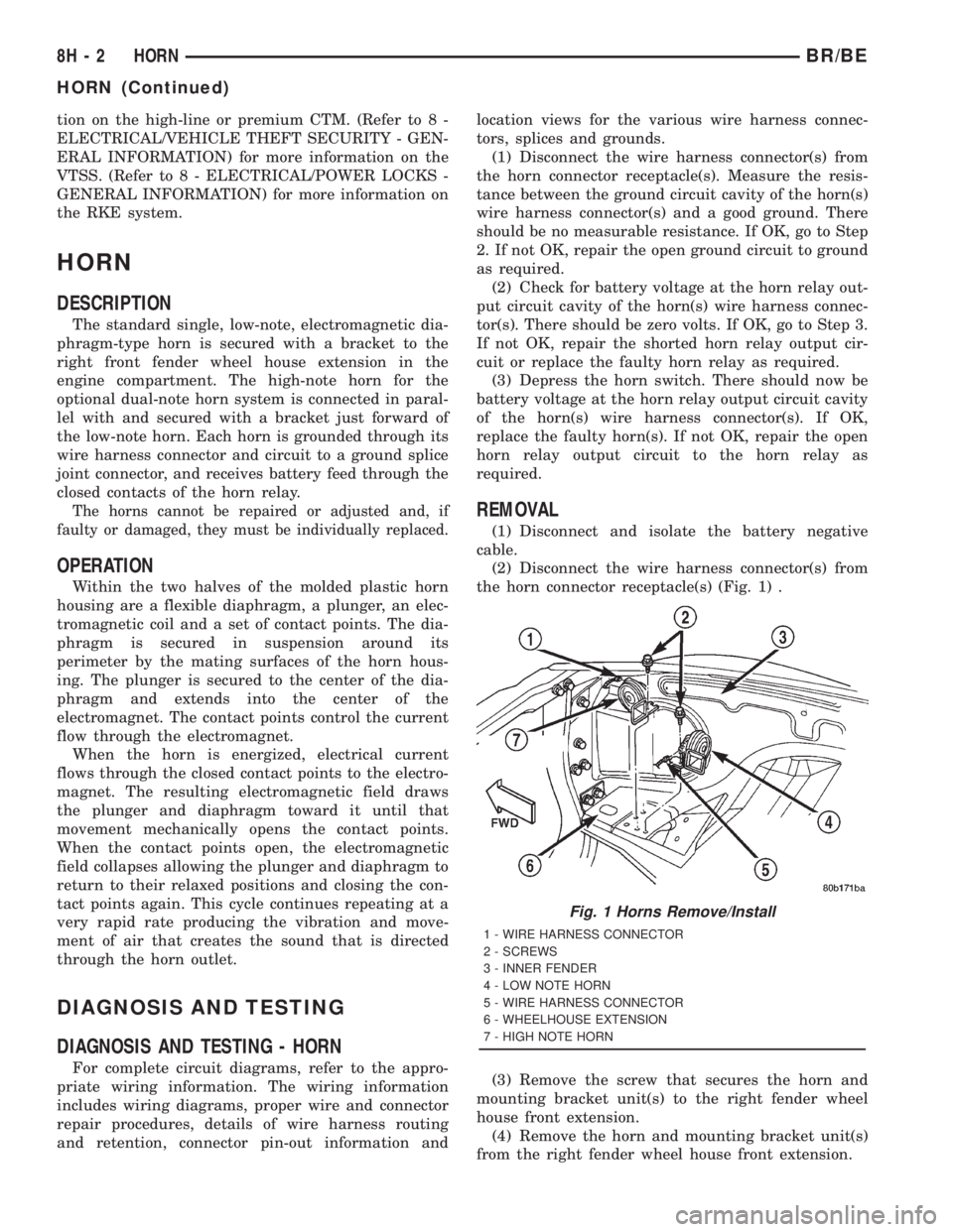
The standard single, low-note, electromagnetic dia-
phragm-type horn is secured with a bracket to the
right front fender wheel house extension in the
engine compartment. The high-note horn for the
optional dual-note horn system is connected in paral-
lel with and secured with a bracket just forward of
the low-note horn. Each horn is grounded through its
wire harness connector and circuit to a ground splice
joint connector, and receives battery feed through the
closed contacts of the horn relay.
The horns cannot be repaired or adjusted and, if
faulty or damaged, they must be individually replaced.
OPERATION
Within the two halves of the molded plastic horn
housing are a flexible diaphragm, a plunger, an elec-
tromagnetic coil and a set of contact points. The dia-
phragm is secured in suspension around its
perimeter by the mating surfaces of the horn hous-
ing. The plunger is secured to the center of the dia-
phragm and extends into the center of the
electromagnet. The contact points control the current
flow through the electromagnet.
When the horn is energized, electrical current
flows through the closed contact points to the electro-
magnet. The resulting electromagnetic field draws
the plunger and diaphragm toward it until that
movement mechanically opens the contact points.
When the contact points open, the electromagnetic
field collapses allowing the plunger and diaphragm to
return to their relaxed positions and closing the con-
tact points again. This cycle continues repeating at a
very rapid rate producing the vibration and move-
ment of air that creates the sound that is directed
through the horn outlet.
DIAGNOSIS AND TESTING
DIAGNOSIS AND TESTING - HORN
For complete circuit diagrams, refer to the appro-
priate wiring information. The wiring information
includes wiring diagrams, proper wire and connector
repair procedures, details of wire harness routing
and retention, connector pin-out information andlocation views for the various wire harness connec-
tors, splices and grounds.
(1) Disconnect the wire harness connector(s) from
the horn connector receptacle(s). Measure the resis-
tance between the ground circuit cavity of the horn(s)
wire harness connector(s) and a good ground. There
should be no measurable resistance. If OK, go to Step
2. If not OK, repair the open ground circuit to ground
as required.
(2) Check for battery voltage at the horn relay out-
put circuit cavity of the horn(s) wire harness connec-
tor(s). There should be zero volts. If OK, go to Step 3.
If not OK, repair the shorted horn relay output cir-
cuit or replace the faulty horn relay as required.
(3) Depress the horn switch. There should now be
battery voltage at the horn relay output circuit cavity
of the horn(s) wire harness connector(s). If OK,
replace the faulty horn(s). If not OK, repair the open
horn relay output circuit to the horn relay as
required.
REMOVAL
(1) Disconnect and isolate the battery negative
cable.
(2) Disconnect the wire harness connector(s) from
the horn connector receptacle(s) (Fig. 1) .
(3) Remove the screw that secures the horn and
mounting bracket unit(s) to the right fender wheel
house front extension.
(4) Remove the horn and mounting bracket unit(s)
from the right fender wheel house front extension.
Fig. 1 Horns Remove/Install
1 - WIRE HARNESS CONNECTOR
2 - SCREWS
3 - INNER FENDER
4 - LOW NOTE HORN
5 - WIRE HARNESS CONNECTOR
6 - WHEELHOUSE EXTENSION
7 - HIGH NOTE HORN
8H - 2 HORNBR/BE
HORN (Continued)
Page 534 of 2889
INSTALLATION
(1) Position the horn and mounting bracket unit(s)
onto the right fender wheel house front extension.
(2) Install and tighten the screw that secures the
horn and mounting bracket unit(s) to the right
fender wheel house front extension. Tighten the
screw to 11 N´m (95 in. lbs.).
(3) Reconnect the wire harness connector(s) to the
horn connector receptacle(s).
(4) Reconnect the battery negative cable.
HORN RELAY
DESCRIPTION
The horn relay is a electromechanical device that
switches battery current to the horn when the horn
switch grounds the relay coil. The horn relay is
located in the Power Distribution Center (PDC) in
the engine compartment. If a problem is encountered
with a continuously sounding horn, it can usually be
quickly resolved by removing the horn relay from the
PDC until further diagnosis is completed. See the
fuse and relay layout label affixed to the inside sur-
face of the PDC cover for horn relay identification
and location.
The horn relay is a International Standards Orga-
nization (ISO) micro-relay. Relays conforming to the
ISO specifications have common physical dimensions,
current capacities, terminal patterns, and terminal
functions. The ISO micro-relay terminal functions
are the same as a conventional ISO relay. However,
the ISO micro-relay terminal pattern (or footprint) is
different, the current capacity is lower, and the phys-
ical dimensions are smaller than those of the conven-
tional ISO relay.
The horn relay cannot be repaired or adjusted and,
if faulty or damaged, it must be replaced.
OPERATION
The ISO relay consists of an electromagnetic coil, a
resistor or diode, and three (two fixed and one mov-
able) electrical contacts. The movable (common feed)
relay contact is held against one of the fixed contacts
(normally closed) by spring pressure. When the elec-
tromagnetic coil is energized, it draws the movable
contact away from the normally closed fixed contact,
and holds it against the other (normally open) fixed
contact.
When the electromagnetic coil is de-energized,
spring pressure returns the movable contact to the
normally closed position. The resistor or diode is con-
nected in parallel with the electromagnetic coil in the
relay, and helps to dissipate voltage spikes that are
produced when the coil is de-energized.
DIAGNOSIS AND TESTING
DIAGNOSIS AND TESTING - HORN RELAY
The horn relay (Fig. 2) is located in the Power Dis-
tribution Center (PDC) behind the battery on the
driver side of the engine compartment. If a problem
is encountered with a continuously sounding horn, it
can usually be quickly resolved by removing the horn
relay from the PDC until further diagnosis is com-
pleted. See the fuse and relay layout label affixed to
the inside surface of the PDC cover for horn relay
identification and location. For complete circuit dia-
grams, refer to the appropriate wiring information.
The wiring information includes wiring diagrams,
proper wire and connector repair procedures, details
of wire harness routing and retention, connector pin-
out information and location views for the various
wire harness connectors, splices and grounds.
WARNING: ON VEHICLES EQUIPPED WITH AIR-
BAGS, REFER TO ELECTRICAL, RESTRAINTS
BEFORE ATTEMPTING ANY STEERING WHEEL,
STEERING COLUMN, OR INSTRUMENT PANEL
COMPONENT DIAGNOSIS OR SERVICE. FAILURE
TO TAKE THE PROPER PRECAUTIONS COULD
RESULT IN ACCIDENTAL AIRBAG DEPLOYMENT
AND POSSIBLE PERSONAL INJURY.
(1) Remove the horn relay from the PDC. (Refer to
8 - ELECTRICAL/HORN/HORN RELAY -
REMOVAL) for the procedures.
(2) A relay in the de-energized position should
have continuity between terminals 87A and 30, and
no continuity between terminals 87 and 30. If OK, go
to Step 3. If not OK, replace the faulty relay.
(3) Resistance between terminals 85 and 86 (elec-
tromagnet) should be 7565 ohms. If OK, go to Step
4. If not OK, replace the faulty relay.
(4) Connect a battery to terminals 85 and 86.
There should now be continuity between terminals
30 and 87, and no continuity between terminals 87A
and 30. If OK, perform the Relay Circuit Test that
follows. If not OK, replace the faulty relay.
RELAY CIRCUIT TEST
(1) The relay common feed terminal cavity (30) is
connected to battery voltage and should be hot at all
times. If OK, go to Step 2. If not OK, repair the open
circuit to the fuse in the PDC as required.
(2) The relay normally closed terminal (87A) is
connected to terminal 30 in the de-energized position,
but is not used for this application. Go to Step 3.
BR/BEHORN 8H - 3
HORN (Continued)
Page 535 of 2889
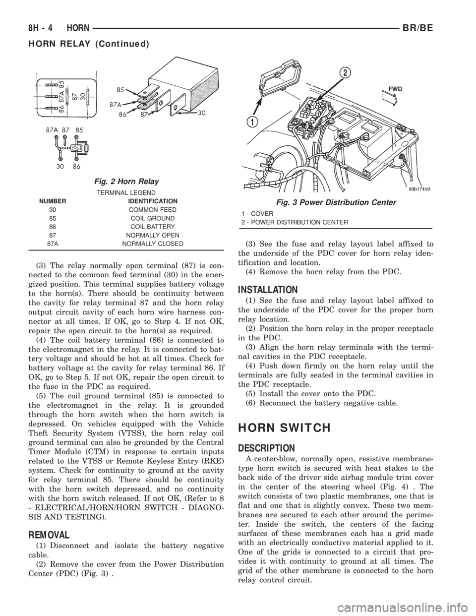
(3) The relay normally open terminal (87) is con-
nected to the common feed terminal (30) in the ener-
gized position. This terminal supplies battery voltage
to the horn(s). There should be continuity between
the cavity for relay terminal 87 and the horn relay
output circuit cavity of each horn wire harness con-
nector at all times. If OK, go to Step 4. If not OK,
repair the open circuit to the horn(s) as required.
(4) The coil battery terminal (86) is connected to
the electromagnet in the relay. It is connected to bat-
tery voltage and should be hot at all times. Check for
battery voltage at the cavity for relay terminal 86. If
OK, go to Step 5. If not OK, repair the open circuit to
the fuse in the PDC as required.
(5) The coil ground terminal (85) is connected to
the electromagnet in the relay. It is grounded
through the horn switch when the horn switch is
depressed. On vehicles equipped with the Vehicle
Theft Security System (VTSS), the horn relay coil
ground terminal can also be grounded by the Central
Timer Module (CTM) in response to certain inputs
related to the VTSS or Remote Keyless Entry (RKE)
system. Check for continuity to ground at the cavity
for relay terminal 85. There should be continuity
with the horn switch depressed, and no continuity
with the horn switch released. If not OK, (Refer to 8
- ELECTRICAL/HORN/HORN SWITCH - DIAGNO-
SIS AND TESTING).
REMOVAL
(1) Disconnect and isolate the battery negative
cable.
(2) Remove the cover from the Power Distribution
Center (PDC) (Fig. 3) .(3) See the fuse and relay layout label affixed to
the underside of the PDC cover for horn relay iden-
tification and location.
(4) Remove the horn relay from the PDC.
INSTALLATION
(1) See the fuse and relay layout label affixed to
the underside of the PDC cover for the proper horn
relay location.
(2) Position the horn relay in the proper receptacle
in the PDC.
(3) Align the horn relay terminals with the termi-
nal cavities in the PDC receptacle.
(4) Push down firmly on the horn relay until the
terminals are fully seated in the terminal cavities in
the PDC receptacle.
(5) Install the cover onto the PDC.
(6) Reconnect the battery negative cable.
HORN SWITCH
DESCRIPTION
A center-blow, normally open, resistive membrane-
type horn switch is secured with heat stakes to the
back side of the driver side airbag module trim cover
in the center of the steering wheel (Fig. 4) . The
switch consists of two plastic membranes, one that is
flat and one that is slightly convex. These two mem-
branes are secured to each other around the perime-
ter. Inside the switch, the centers of the facing
surfaces of these membranes each has a grid made
with an electrically conductive material applied to it.
One of the grids is connected to a circuit that pro-
vides it with continuity to ground at all times. The
grid of the other membrane is connected to the horn
relay control circuit.
Fig. 2 Horn Relay
TERMINAL LEGEND
NUMBER IDENTIFICATION
30 COMMON FEED
85 COIL GROUND
86 COIL BATTERY
87 NORMALLY OPEN
87A NORMALLY CLOSED
Fig. 3 Power Distribution Center
1 - COVER
2 - POWER DISTRIBUTION CENTER
8H - 4 HORNBR/BE
HORN RELAY (Continued)