2001 DODGE RAM Heating & air conditioning
[x] Cancel search: Heating & air conditioningPage 1 of 2889

GROUP TAB LOCATOR
Introduction
0Lubrication & Maintenance
2Suspension
3Differential & Driveline
5Brakes
7Cooling
8AAudio
8BChime/Buzzer
8EElectronic Control Modules
8FEngine Systems
8GHeated Systems
8HHorn
8IIgnition Control
8JInstrument Cluster
8LLamps
8MMessage Systems
8NPower Systems
8ORestraints
8PSpeed Control
8QVehicle Theft Security
8RWipers/Washers
8WWiring
9Engine
11Exhaust System
13Frame & Bumpers
14Fuel System
19Steering
21Transmission/Transaxle
22Tires/Wheels
23Body
24Heating & Air Conditioning
25Emissions Control Systems
30New Vehicle Preparation
Component and System Index
Service Manual Comment Forms (Rear of Manual)
Page 339 of 2889
OPERATIONÐCOOLING SYSTEM
The cooling system regulates engine operating tem-
perature. It allows the engine to reach normal oper-
ating temperature as quickly as possible. It also
maintains normal operating temperature and pre-
vents overheating.
The cooling system also provides a means of heat-
ing the passenger compartment and cooling the auto-
matic transmission fluid (if equipped). The cooling
system is pressurized and uses a centrifugal water
pump to circulate coolant throughout the system.
An optional factory installed maximum duty cool-
ing package is available on most models. This pack-
age will provide additional cooling capacity for
vehicles used under extreme conditions such as
trailer towing in high ambient temperatures.
DIAGNOSIS AND TESTING - PRELIMINARY
CHECKS
ENGINE COOLING SYSTEM OVERHEATING
Establish what driving conditions caused the com-
plaint. Abnormal loads on the cooling system such as
the following may be the cause:
²PROLONGED IDLE
²VERY HIGH AMBIENT TEMPERATURE
²SLIGHT TAIL WIND AT IDLE
²SLOW TRAFFIC
²TRAFFIC JAMS
²HIGH SPEED OR STEEP GRADES
Driving techniques that avoid overheating are:
²Idle with A/C off when temperature gauge is at
end of normal range.²Increasing engine speed for more air flow is rec-
ommended.
TRAILER TOWING:
Consult Trailer Towing section of owners manual.
Do not exceed limits.
AIR CONDITIONING; ADD-ON OR AFTER MARKET:
A maximum cooling package should have been
ordered with vehicle if add-on or after market A/C is
installed. If not, maximum cooling system compo-
nents should be installed for model involved per
manufacturer's specifications.
RECENT SERVICE OR ACCIDENT REPAIR:
Determine if any recent service has been per-
formed on vehicle that may effect cooling system.
This may be:
²Engine adjustments (incorrect timing)
²Slipping engine accessory drive belt(s)
²Brakes (possibly dragging)
²Changed parts. Incorrect water pump or pump
rotating in wrong direction due to belt not correctly
routed
²Reconditioned radiator or cooling system refill-
ing (possibly under filled or air trapped in system).
NOTE: If investigation reveals none of the previous
items as a cause for an engine overheating com-
plaint, (Refer to 7 - COOLING - DIAGNOSIS AND
TESTING)
DIAGNOSIS AND TESTINGÐON-BOARD
DIAGNOSTICS (OBD)
COOLING SYSTEM RELATED DIAGNOSTICS
The powertrain control module (PCM) has been
programmed to monitor certain cooling system com-
ponents:
²If the engine has remained cool for too long a
period, such as with a stuck open thermostat, a Diag-
nostic Trouble Code (DTC) can be set.
²If an open or shorted condition has developed in
the relay circuit controlling the electric radiator fan,
a Diagnostic Trouble Code (DTC) can be set.
If the problem is sensed in a monitored circuit
often enough to indicated an actual problem, a DTC
is stored. The DTC will be stored in the PCM mem-
ory for eventual display to the service technician.
(Refer to 25 - EMISSIONS CONTROL - DESCRIP-
TION).
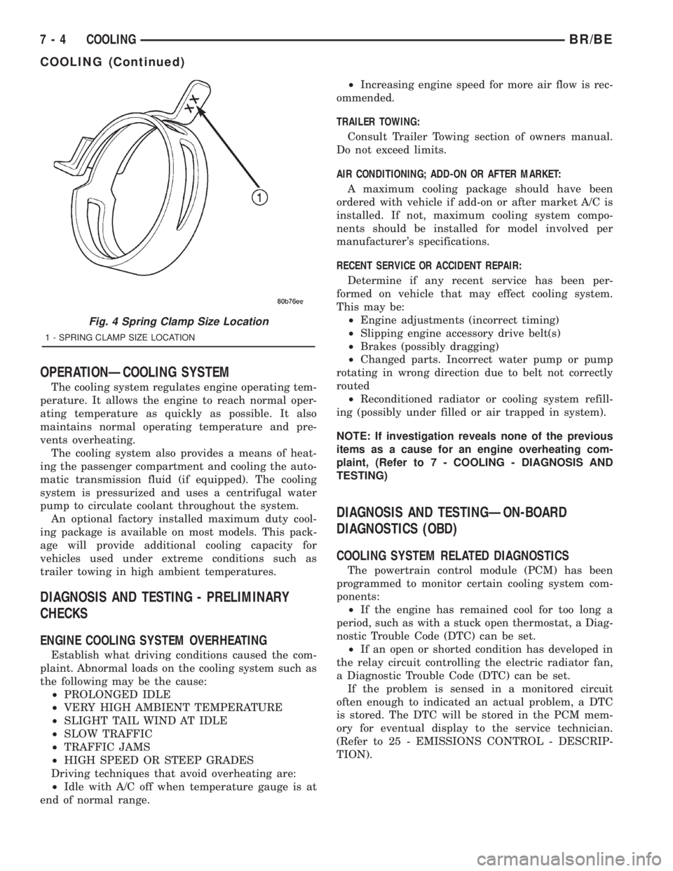
Fig. 4 Spring Clamp Size Location
1 - SPRING CLAMP SIZE LOCATION
7 - 4 COOLINGBR/BE
COOLING (Continued)
Page 342 of 2889

DIAGNOSIS AND TESTING - COOLING SYSTEM
GAS ENGINE
COOLING SYSTEM DIAGNOSISÐGASOLINE ENGINE
CONDITION POSSIBLE CAUSES CORRECTION
TEMPERATURE
GAUGE READS LOW1. Has a Diagnostic Trouble Code (DTC)
been set indicating a stuck open
thermostat?1. (Refer to 25 - EMISSIONS CONTROL -
DESCRIPTION) for On-Board Diagnostics
and DTC information. Replace thermostat
if necessary.
2. Is the temperature sending unit
connected?2. Check the temperature sensor
connector. (Refer to 8 - ELECTRICAL/
INSTRUMENT CLUSTER - SCHEMATIC -
ELECTRICAL) Repair connector if
necessary.
3. Is the temperature gauge operating
OK?3. Check gauge operation. (Refer to 8 -
ELECTRICAL/INSTRUMENT CLUSTER/
ENGINE TEMPERATURE GAUGE -
DESCRIPTION) . Repair as necessary.
4. Coolant level low in cold ambient
temperatures accompanied with poor
heater performance.4. Check coolant level in the coolant
reserve/overflow tank and the radiator.
Inspect system for leaks. Repair leaks as
necessary. Refer to the Coolant section of
the manual text for WARNINGS and
CAUTIONS associated with removing the
radiator cap.
5. Improper operation of internal heater
doors or heater controls.5. Inspect heater and repair as necessary.
(Refer to 24 - HEATING & AIR
CONDITIONING - DIAGNOSIS AND
TESTING) for procedures.
TEMPERATURE
GAUGE READS HIGH
OR THE COOLANT
WARNING LAMP
ILLUMINATES.
COOLANT MAY OR
MAY NOT BE LOST OR
LEAKING FROM THE
COOLING SYSTEM1. Trailer is being towed, a steep hill is
being climbed, vehicle is operated in slow
moving traffic, or engine is being idled
with very high ambient (outside)
temperatures and the air conditioning is
on. Higher altitudes could aggravate
these conditions.1. This may be a temporary condition and
repair is not necessary. Turn off the air
conditioning and attempt to drive the
vehicle without any of the previous
conditions. Observe the temperature
gauge. The gauge should return to the
normal range. If the gauge does not
return to the normal range, determine the
cause for overheating and repair. Refer to
Possible Causes (2-20).
2. Is the temperature gauge reading
correctly?2. Check gauge. (Refer to 8 -
ELECTRICAL/INSTRUMENT CLUSTER -
SCHEMATIC - ELECTRICAL) . Repair as
necessary.
3. Is the temperature warning illuminating
unnecessarily?3. (Refer to 8 - ELECTRICAL/
INSTRUMENT CLUSTER - SCHEMATIC -
ELECTRICAL).
4. Coolant low in coolant reserve/overflow
tank and radiator?4. Check for coolant leaks and repair as
necessary. (Refer to 7 - COOLING -
DIAGNOSIS AND TESTING).
BR/BECOOLING 7 - 7
COOLING (Continued)
Page 344 of 2889

CONDITION POSSIBLE CAUSES CORRECTION
16. Thermostat partially or completely
shut.16. Check thermostat operation and
replace as necessary. (Refer to 7 -
COOLING/ENGINE/ENGINE COOLANT
THERMOSTAT - REMOVAL) .
17. Viscous fan drive not operating
properly.17. Check fan drive operation and replace
as necessary. (Refer to 7 - COOLING/
ENGINE/FAN DRIVE VISCOUS CLUTCH
- REMOVAL) .
18. Cylinder head gasket leaking. 18. Check for cylinder head gasket leaks.
(Refer to 7 - COOLING - DIAGNOSIS
AND TESTING).
19. Heater core leaking. 19. Check heater core for leaks. (Refer to
24 - HEATING & AIR CONDITIONING/
PLUMBING - DIAGNOSIS AND
TESTING). Repair as necessary.
TEMPERATURE
GAUGE READING IS
INCONSISTENT
(FLUCTUATES,
CYCLES OR IS
ERRATIC)1. During cold weather operation, with the
heater blower in the high position, the
gauge reading may drop slightly.1. A normal condition. No correction is
necessary.
2. Temperature gauge or engine mounted
gauge sensor defective or shorted. Also,
corroded or loose wiring in this circuit.2. Check operation of gauge and repair if
necessary. (Refer to 8 - ELECTRICAL/
INSTRUMENT CLUSTER - DIAGNOSIS
AND TESTING).
3. Gauge reading rises when vehicle is
brought to a stop after heavy use (engine
still running)3. A normal condition. No correction is
necessary. Gauge should return to normal
range after vehicle is driven.
4. Gauge reading high after re-starting a
warmed up (hot) engine.4. A normal condition. No correction is
necessary. The gauge should return to
normal range after a few minutes of
engine operation.
5. Coolant level low in radiator (air will
build up in the cooling system causing
the thermostat to open late).5. Check and correct coolant leaks. (Refer
to 7 - COOLING - DIAGNOSIS AND
TESTING).
6. Cylinder head gasket leaking allowing
exhaust gas to enter cooling system
causing a thermostat to open late.6. (a) Check for cylinder head gasket
leaks. (Refer to 7 - COOLING -
DIAGNOSIS AND TESTING).
(b) Check for coolant in the engine oil.
Inspect for white steam emitting from the
exhaust system. Repair as necessary.
7. Water pump impeller loose on shaft. 7. Check water pump and replace as
necessary. (Refer to 7 - COOLING/
ENGINE/WATER PUMP - REMOVAL).
8. Loose accessory drive belt. (water
pump slipping)8. (Refer to 7 - COOLING/ACCESSORY
DRIVE/DRIVE BELTS - DIAGNOSIS AND
TESTING). Check and correct as
necessary.
9. Air leak on the suction side of the
water pump allows air to build up in
cooling system causing thermostat to
open late.9. Locate leak and repair as necessary.
BR/BECOOLING 7 - 9
COOLING (Continued)
Page 346 of 2889
CONDITION POSSIBLE CAUSES CORRECTION
NOISY VISCOUS
FAN/DRIVE1. Fan blades loose. 1. Replace fan blade assembly. (Refer to
7 - COOLING/ENGINE/RADIATOR FAN -
REMOVAL)
2. Fan blades striking a surrounding
object.2. Locate point of fan blade contact and
repair as necessary.
3. Air obstructions at radiator or air
conditioning condenser.3. Remove obstructions and/or clean
debris or insects from radiator or A/C
condenser.
4. Thermal viscous fan drive has
defective bearing.4. Replace fan drive. Bearing is not
serviceable. (Refer to 7 - COOLING/
ENGINE/FAN DRIVE VISCOUS CLUTCH
- REMOVAL).
5. A certain amount of fan noise may be
evident on models equipped with a
thermal viscous fan drive. Some of this
noise is normal.5. (Refer to 7 - COOLING/ENGINE/FAN
DRIVE VISCOUS CLUTCH -
DESCRIPTION) for an explanation of
normal fan noise.
INADEQUATE HEATER
PERFORMANCE.
THERMOSTAT FAILED
IN OPEN POSITION1. Has a Diagnostic trouble Code (DTC)
been set?1. (Refer to 25 - EMISSIONS CONTROL -
DESCRIPTION) for correct procedures
and replace thermostat if necessary
2. Coolant level low 2. (Refer to 7 - COOLING - DIAGNOSIS
AND TESTING).
3. Obstructions in heater hose/fittings 3. Remove heater hoses at both ends and
check for obstructions
4. Heater hose kinked 4. Locate kinked area and repair as
necessary
5. Water pump is not pumping water
to/through the heater core. When the
engine is fully warmed up, both heater
hoses should be hot to the touch. If only
one of the hoses is hot, the water pump
may not be operating correctly or the
heater core may be plugged. Accessory
drive belt may be slipping causing poor
water pump operation.5. (Refer to 7 - COOLING/ENGINE/
WATER PUMP - REMOVAL). If a slipping
belt is detected, (Refer to 7 - COOLING/
ACCESSORY DRIVE/DRIVE BELTS -
DIAGNOSIS AND TESTING). If heater
core obstruction is detected, (Refer to 24
- HEATING & AIR CONDITIONING/
PLUMBING/HEATER CORE -
REMOVAL).
STEAM IS COMING
FROM THE FRONT OF
VEHICLE NEAR THE
GRILL AREA WHEN
WEATHER IS WET,
ENGINE IS WARMED
UP AND RUNNING,
AND VEHICLE IS
STATIONARY.
TEMPERATURE
GAUGE IS IN NORMAL
RANGE1. During wet weather, moisture (snow,
ice or rain condensation) on the radiator
will evaporate when the thermostat
opens. This opening allows heated water
into the radiator. When the moisture
contacts the hot radiator, steam may be
emitted. This usually occurs in cold
weather with no fan or airflow to blow it
away.1. Occasional steam emitting from this
area is normal. No repair is necessary.
BR/BECOOLING 7 - 11
COOLING (Continued)
Page 354 of 2889
ACCESSORY DRIVE
TABLE OF CONTENTS
page page
BELT TENSIONERS - 3.9L/5.2L/5.9L
DESCRIPTION...........................19
OPERATION.............................19
REMOVAL..............................20
INSTALLATION...........................20
BELT TENSIONERS - 8.0L
DESCRIPTION...........................20
OPERATION.............................20
REMOVAL..............................21
INSTALLATION...........................22
BELT TENSIONERS - 5.9L DIESEL
DESCRIPTION...........................23
OPERATION.............................23
REMOVAL..............................23
INSTALLATION...........................23
DRIVE BELTS - 3.9L/5.2L/5.9L
DIAGNOSIS AND TESTING.................24
ACCESSORY DRIVE BELT................24
REMOVAL..............................26INSTALLATION...........................27
DRIVE BELTS - 8.0L
DIAGNOSIS AND TESTING.................27
ACCESSORY DRIVE BELT................27
REMOVAL..............................30
INSTALLATION...........................30
DRIVE BELTS - 5.9L DIESEL
DIAGNOSIS AND TESTING.................31
ACCESSORY DRIVE BELT................31
REMOVAL..............................33
INSTALLATION...........................34
VACUUM PUMP - 5.9L DIESEL
DESCRIPTION...........................34
OPERATION.............................35
DIAGNOSIS AND TESTING.................35
VACUUM PUMP OUTPUT.................35
REMOVAL..............................35
INSTALLATION...........................37
BELT TENSIONERS - 3.9L/5.2L/
5.9L
DESCRIPTION
Correct drive belt tension is required to ensure
optimum performance of the belt driven engine acces-
sories. If specified tension is not maintained, belt
slippage may cause; engine overheating, lack of
power steering assist, loss of air conditioning capac-
ity, reduced generator output rate, and greatly
reduced belt life.
It is not necessary to adjust belt tension on the
3.9L/5.2L or 5.9L engines. These engines are
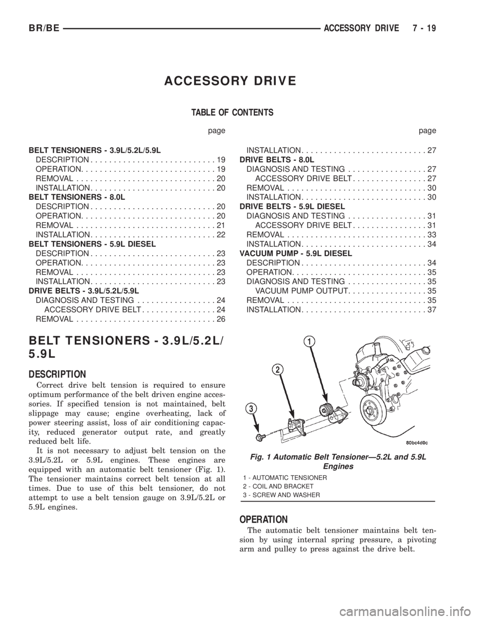
equipped with an automatic belt tensioner (Fig. 1).
The tensioner maintains correct belt tension at all
times. Due to use of this belt tensioner, do not
attempt to use a belt tension gauge on 3.9L/5.2L or
5.9L engines.
OPERATION
The automatic belt tensioner maintains belt ten-
sion by using internal spring pressure, a pivoting
arm and pulley to press against the drive belt.
Fig. 1 Automatic Belt TensionerÐ5.2L and 5.9L
Engines
1 - AUTOMATIC TENSIONER
2 - COIL AND BRACKET
3 - SCREW AND WASHER
BR/BEACCESSORY DRIVE 7 - 19
Page 409 of 2889
²Water leaks from the shaft seal. This is evident
by traces of coolant below the vent hole
²Loose or rough turning bearing. Also inspect
thermal fan drive
²Impeller rubbing the pump body
INSTALLATION
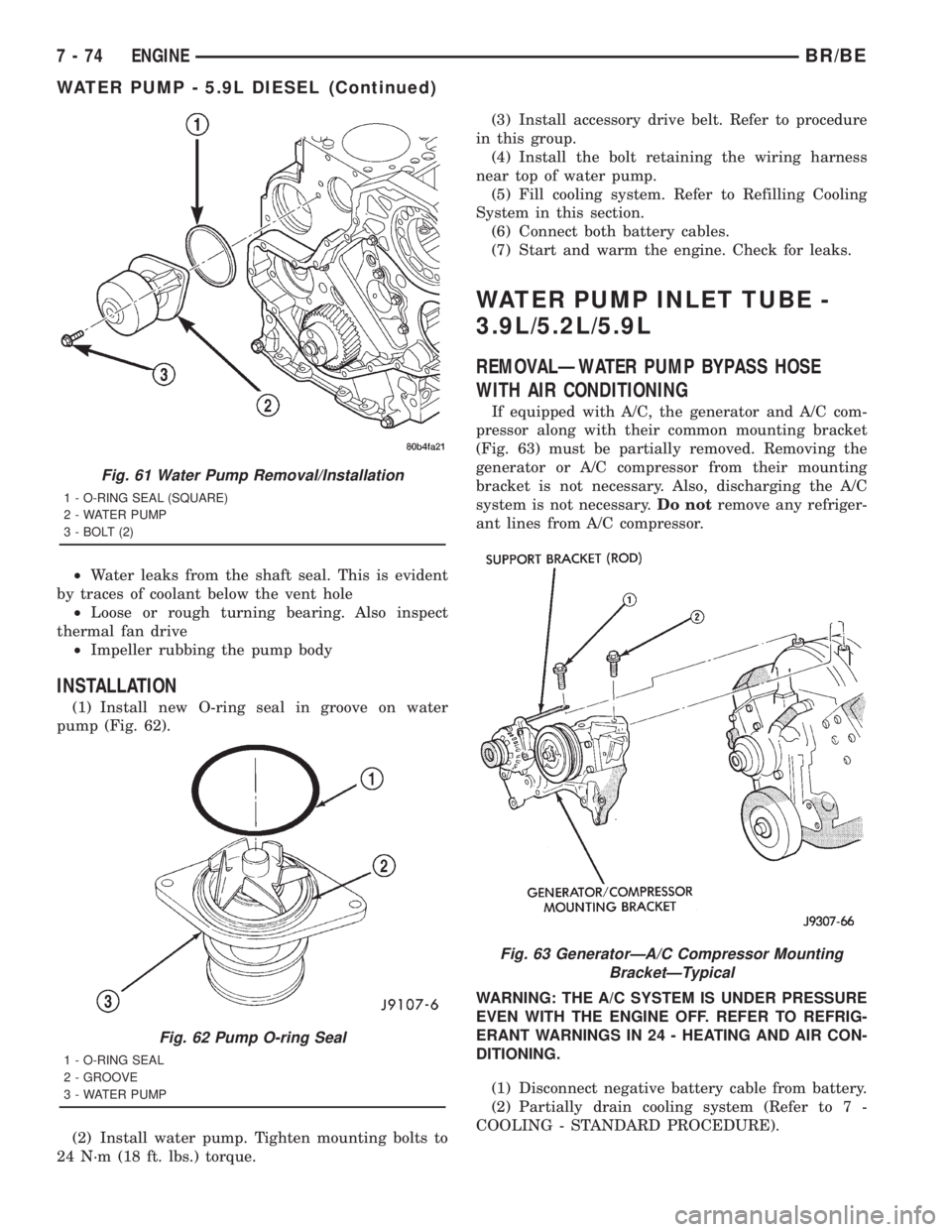
(1) Install new O-ring seal in groove on water
pump (Fig. 62).
(2) Install water pump. Tighten mounting bolts to
24 N´m (18 ft. lbs.) torque.(3) Install accessory drive belt. Refer to procedure
in this group.
(4) Install the bolt retaining the wiring harness
near top of water pump.
(5) Fill cooling system. Refer to Refilling Cooling
System in this section.
(6) Connect both battery cables.
(7) Start and warm the engine. Check for leaks.
WATER PUMP INLET TUBE -
3.9L/5.2L/5.9L
REMOVALÐWATER PUMP BYPASS HOSE
WITH AIR CONDITIONING
If equipped with A/C, the generator and A/C com-
pressor along with their common mounting bracket
(Fig. 63) must be partially removed. Removing the
generator or A/C compressor from their mounting
bracket is not necessary. Also, discharging the A/C
system is not necessary.Do notremove any refriger-
ant lines from A/C compressor.
WARNING: THE A/C SYSTEM IS UNDER PRESSURE
EVEN WITH THE ENGINE OFF. REFER TO REFRIG-
ERANT WARNINGS IN 24 - HEATING AND AIR CON-
DITIONING.
(1) Disconnect negative battery cable from battery.
(2) Partially drain cooling system (Refer to 7 -
COOLING - STANDARD PROCEDURE).
Fig. 61 Water Pump Removal/Installation
1 - O-RING SEAL (SQUARE)
2 - WATER PUMP
3 - BOLT (2)
Fig. 62 Pump O-ring Seal
1 - O-RING SEAL
2 - GROOVE
3 - WATER PUMP
Fig. 63 GeneratorÐA/C Compressor Mounting
BracketÐTypical
7 - 74 ENGINEBR/BE
WATER PUMP - 5.9L DIESEL (Continued)
Page 518 of 2889
MIRROR SWITCH
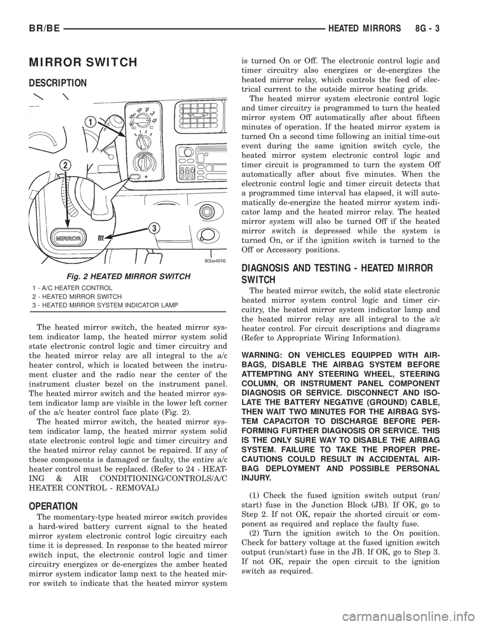
DESCRIPTION
The heated mirror switch, the heated mirror sys-
tem indicator lamp, the heated mirror system solid
state electronic control logic and timer circuitry and
the heated mirror relay are all integral to the a/c
heater control, which is located between the instru-
ment cluster and the radio near the center of the
instrument cluster bezel on the instrument panel.
The heated mirror switch and the heated mirror sys-
tem indicator lamp are visible in the lower left corner
of the a/c heater control face plate (Fig. 2).
The heated mirror switch, the heated mirror sys-
tem indicator lamp, the heated mirror system solid
state electronic control logic and timer circuitry and
the heated mirror relay cannot be repaired. If any of
these components is damaged or faulty, the entire a/c
heater control must be replaced. (Refer to 24 - HEAT-
ING & AIR CONDITIONING/CONTROLS/A/C
HEATER CONTROL - REMOVAL)
OPERATION
The momentary-type heated mirror switch provides
a hard-wired battery current signal to the heated
mirror system electronic control logic circuitry each
time it is depressed. In response to the heated mirror
switch input, the electronic control logic and timer
circuitry energizes or de-energizes the amber heated
mirror system indicator lamp next to the heated mir-
ror switch to indicate that the heated mirror systemis turned On or Off. The electronic control logic and
timer circuitry also energizes or de-energizes the
heated mirror relay, which controls the feed of elec-
trical current to the outside mirror heating grids.
The heated mirror system electronic control logic
and timer circuitry is programmed to turn the heated
mirror system Off automatically after about fifteen
minutes of operation. If the heated mirror system is
turned On a second time following an initial time-out
event during the same ignition switch cycle, the
heated mirror system electronic control logic and
timer circuit is programmed to turn the system Off
automatically after about five minutes. When the
electronic control logic and timer circuit detects that
a programmed time interval has elapsed, it will auto-
matically de-energize the heated mirror system indi-
cator lamp and the heated mirror relay. The heated
mirror system will also be turned Off if the heated
mirror switch is depressed while the system is
turned On, or if the ignition switch is turned to the
Off or Accessory positions.
DIAGNOSIS AND TESTING - HEATED MIRROR
SWITCH
The heated mirror switch, the solid state electronic
heated mirror system control logic and timer cir-
cuitry, the heated mirror system indicator lamp and
the heated mirror relay are all integral to the a/c
heater control. For circuit descriptions and diagrams
(Refer to Appropriate Wiring Information).
WARNING: ON VEHICLES EQUIPPED WITH AIR-
BAGS, DISABLE THE AIRBAG SYSTEM BEFORE
ATTEMPTING ANY STEERING WHEEL, STEERING
COLUMN, OR INSTRUMENT PANEL COMPONENT
DIAGNOSIS OR SERVICE. DISCONNECT AND ISO-
LATE THE BATTERY NEGATIVE (GROUND) CABLE,
THEN WAIT TWO MINUTES FOR THE AIRBAG SYS-
TEM CAPACITOR TO DISCHARGE BEFORE PER-
FORMING FURTHER DIAGNOSIS OR SERVICE. THIS
IS THE ONLY SURE WAY TO DISABLE THE AIRBAG
SYSTEM. FAILURE TO TAKE THE PROPER PRE-
CAUTIONS COULD RESULT IN ACCIDENTAL AIR-
BAG DEPLOYMENT AND POSSIBLE PERSONAL
INJURY.
(1) Check the fused ignition switch output (run/
start) fuse in the Junction Block (JB). If OK, go to
Step 2. If not OK, repair the shorted circuit or com-
ponent as required and replace the faulty fuse.
(2) Turn the ignition switch to the On position.
Check for battery voltage at the fused ignition switch
output (run/start) fuse in the JB. If OK, go to Step 3.
If not OK, repair the open circuit to the ignition
switch as required.
Fig. 2 HEATED MIRROR SWITCH
1 - A/C HEATER CONTROL
2 - HEATED MIRROR SWITCH
3 - HEATED MIRROR SYSTEM INDICATOR LAMP
BR/BEHEATED MIRRORS 8G - 3