2001 DODGE RAM Heating & air conditioning
[x] Cancel search: Heating & air conditioningPage 1415 of 2889
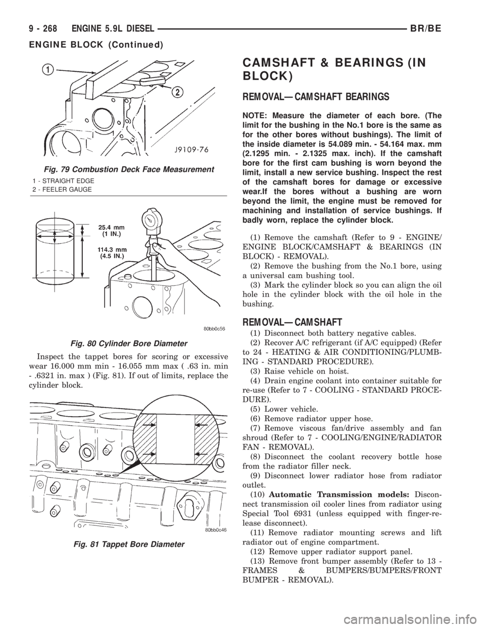
Inspect the tappet bores for scoring or excessive
wear 16.000 mm min - 16.055 mm max ( .63 in. min
- .6321 in. max ) (Fig. 81). If out of limits, replace the
cylinder block.
CAMSHAFT & BEARINGS (IN
BLOCK)
REMOVALÐCAMSHAFT BEARINGS
NOTE: Measure the diameter of each bore. (The
limit for the bushing in the No.1 bore is the same as
for the other bores without bushings). The limit of
the inside diameter is 54.089 min. - 54.164 max. mm
(2.1295 min. - 2.1325 max. inch). If the camshaft
bore for the first cam bushing is worn beyond the
limit, install a new service bushing. Inspect the rest
of the camshaft bores for damage or excessive
wear.If the bores without a bushing are worn
beyond the limit, the engine must be removed for
machining and installation of service bushings. If
badly worn, replace the cylinder block.
(1) Remove the camshaft (Refer to 9 - ENGINE/
ENGINE BLOCK/CAMSHAFT & BEARINGS (IN
BLOCK) - REMOVAL).
(2) Remove the bushing from the No.1 bore, using
a universal cam bushing tool.
(3) Mark the cylinder block so you can align the oil
hole in the cylinder block with the oil hole in the
bushing.
REMOVALÐCAMSHAFT
(1) Disconnect both battery negative cables.
(2) Recover A/C refrigerant (if A/C equipped) (Refer
to 24 - HEATING & AIR CONDITIONING/PLUMB-
ING - STANDARD PROCEDURE).
(3) Raise vehicle on hoist.
(4) Drain engine coolant into container suitable for
re-use (Refer to 7 - COOLING - STANDARD PROCE-
DURE).
(5) Lower vehicle.
(6) Remove radiator upper hose.
(7) Remove viscous fan/drive assembly and fan
shroud (Refer to 7 - COOLING/ENGINE/RADIATOR
FAN - REMOVAL).
(8) Disconnect the coolant recovery bottle hose
from the radiator filler neck.
(9) Disconnect lower radiator hose from radiator
outlet.
(10)Automatic Transmission models:Discon-
nect transmission oil cooler lines from radiator using
Special Tool 6931 (unless equipped with finger-re-
lease disconnect).
(11) Remove radiator mounting screws and lift
radiator out of engine compartment.
(12) Remove upper radiator support panel.
(13) Remove front bumper assembly (Refer to 13 -
FRAMES & BUMPERS/BUMPERS/FRONT
BUMPER - REMOVAL).
Fig. 79 Combustion Deck Face Measurement
1 - STRAIGHT EDGE
2 - FEELER GAUGE
Fig. 80 Cylinder Bore Diameter
Fig. 81 Tappet Bore Diameter
9 - 268 ENGINE 5.9L DIESELBR/BE
ENGINE BLOCK (Continued)
Page 1473 of 2889
(3) Remove the front support bracket.
(4) Discharge the A/C system (Refer to 24 - HEAT-
ING & AIR CONDITIONING/PLUMBING - STAN-
DARD PROCEDURE) and remove the A/C condenser
(Refer to 24 - HEATING & AIR CONDITIONING/
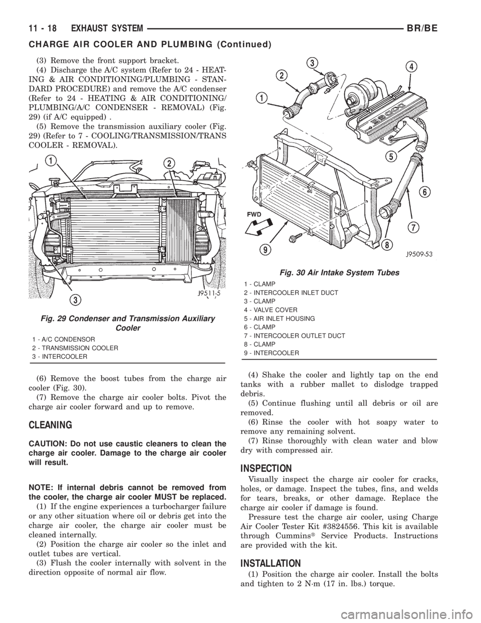
PLUMBING/A/C CONDENSER - REMOVAL) (Fig.
29) (if A/C equipped) .
(5) Remove the transmission auxiliary cooler (Fig.
29) (Refer to 7 - COOLING/TRANSMISSION/TRANS
COOLER - REMOVAL).
(6) Remove the boost tubes from the charge air
cooler (Fig. 30).
(7) Remove the charge air cooler bolts. Pivot the
charge air cooler forward and up to remove.
CLEANING
CAUTION: Do not use caustic cleaners to clean the
charge air cooler. Damage to the charge air cooler
will result.
NOTE: If internal debris cannot be removed from
the cooler, the charge air cooler MUST be replaced.
(1) If the engine experiences a turbocharger failure
or any other situation where oil or debris get into the
charge air cooler, the charge air cooler must be
cleaned internally.
(2) Position the charge air cooler so the inlet and
outlet tubes are vertical.
(3) Flush the cooler internally with solvent in the
direction opposite of normal air flow.(4) Shake the cooler and lightly tap on the end
tanks with a rubber mallet to dislodge trapped
debris.
(5) Continue flushing until all debris or oil are
removed.
(6) Rinse the cooler with hot soapy water to
remove any remaining solvent.
(7) Rinse thoroughly with clean water and blow
dry with compressed air.
INSPECTION
Visually inspect the charge air cooler for cracks,
holes, or damage. Inspect the tubes, fins, and welds
for tears, breaks, or other damage. Replace the
charge air cooler if damage is found.
Pressure test the charge air cooler, using Charge
Air Cooler Tester Kit #3824556. This kit is available
through CumminstService Products. Instructions
are provided with the kit.
INSTALLATION
(1) Position the charge air cooler. Install the bolts
and tighten to 2 N´m (17 in. lbs.) torque.
Fig. 29 Condenser and Transmission Auxiliary
Cooler
1 - A/C CONDENSOR
2 - TRANSMISSION COOLER
3 - INTERCOOLER
Fig. 30 Air Intake System Tubes
1 - CLAMP
2 - INTERCOOLER INLET DUCT
3 - CLAMP
4 - VALVE COVER
5 - AIR INLET HOUSING
6 - CLAMP
7 - INTERCOOLER OUTLET DUCT
8 - CLAMP
9 - INTERCOOLER
11 - 18 EXHAUST SYSTEMBR/BE
CHARGE AIR COOLER AND PLUMBING (Continued)
Page 1474 of 2889

(2) Install the air intake system tubes to the
charge air cooler . With the clamps in position,
tighten the clamps to 11 N´m (95 in. lbs.) torque.
(3) Install the transmission auxiliary cooler (if
equipped) (Refer to 7 - COOLING/TRANSMISSION/
TRANS COOLER - INSTALLATION).
(4) Install the A/C condenser (if A/C equipped)
(Refer to 24 - HEATING & AIR CONDITIONING/
PLUMBING/A/C CONDENSER - INSTALLATION).
Recharge A/C system (Refer to 24 - HEATING & AIRCONDITIONING/PLUMBING - STANDARD PRO-
CEDURE).
(5) Install the front support bracket. Install and
tighten the bolts.
(6) Install the front bumper (Refer to 13 -
FRAMES & BUMPERS/BUMPERS/FRONT
BUMPER - INSTALLATION).
(7) Connect the battery negative cables.
(8) Start engine and check for boost system leaks.
BR/BEEXHAUST SYSTEM 11 - 19
CHARGE AIR COOLER AND PLUMBING (Continued)
Page 2678 of 2889
hook formations on the lower edge of the glove box
door are engaged with and pivot on three hinge pins
integral to the lower edge of the instrument panel
support structure. The glove box door also serves as
the passenger side knee blocker. A honeycomb struc-
ture between the inner and outer glove box door pan-
els helps to absorb the impact load and distribute it
to the instrument panel structure.
²Steering Column Opening Cover- The steer-
ing column opening cover serves as the driver side
knee blocker. This molded plastic cover has an inte-
gral ribbed plastic liner concealed behind it, for
increased strength and integrity. The steering column
opening cover transfers impact loads to the instru-
ment panel structural support.
²Top Cover- The instrument panel top cover or
base trim is the molded, grained, and color impreg-
nated plastic outer skin of the instrument panel
structural support.
Hard wired circuitry connects the electrical compo-
nents on the instrument panel to each other through
the electrical system of the vehicle. These hard wired
circuits are integral to several wire harnesses, which
are routed throughout the vehicle and retained by
many different methods. These circuits may be con-
nected to each other, to the vehicle electrical system
and to the instrument panel components through the
use of a combination of soldered splices, splice block
connectors and many different types of wire harness
terminal connectors and insulators. Refer to the
appropriate wiring information. The wiring informa-
tion includes complete circuit diagrams, proper wire
and connector repair procedures, further details on
wire harness routing and retention, as well as pin-
out and location views for the various wire harness
connectors, splices, and grounds.
OPERATION
The instrument panel serves as the command cen-
ter of the vehicle, which necessarily makes it a very
complex unit. The instrument panel is designed to
house the controls and monitors for standard and
optional powertrains, climate control systems, audio
systems, safety systems, and many other comfort or
convenience items. When the components of the
instrument panel structural support are properly
assembled and secured in the vehicle they provide
superior instrument panel stiffness and integrity to
help reduce buzzes, squeaks, and rattles. This type of
construction also provides improved energy absorp-
tion which, in conjunction with the dual airbags and
seat belts, helps to improve occupant protection.
The instrument panel is also designed so that all of
the various controls can be safely reached and the
monitors can be easily viewed by the vehicle operator
when driving, while still allowing relative ease ofaccess to each of these items for service. Modular
instrument panel construction allows all of the
gauges and controls to be serviced from the front of
the panel. In addition, most of the instrument panel
electrical components can be accessed without com-
plete instrument panel removal. However, if neces-
sary, the instrument panel can be removed from the
vehicle as an assembly.
The steering column opening cover with its inte-
gral knee blocker located on the driver side of the
instrument panel works in conjunction with the air-
bag system in a frontal vehicle impact to keep the
driver properly positioned for an airbag deployment.
In addition, removal of this component provides
access to the steering column mounts, the steering
column wiring, the Junction Block (JB) (removal of a
snap-fit fuse access panel on the left end of the
instrument panel allows access to the fuses and cir-
cuit breakers), the Central Timer Module (CTM), the
Infinity speaker filter choke and relay unit, much of
the instrument panel wiring, and the gear selector
indicator cable (automatic transmission).
In a frontal collision, the glove box door on the pas-
senger side of the instrument panel provides the
same function for the front seat passenger as the
knee blocker does for the driver. The glove box door
also incorporates a recessed latch handle. Removal of
the glove box provides access to the passenger airbag,
the glove box lamp and switch, the radio antenna
coaxial cable, the heating and air conditioning vac-
uum harness connector, and additional instrument
panel wiring.
Removal of the instrument panel cluster bezel
allows access to the headlamp switch, instrument
cluster, radio, passenger airbag on-off switch, heated
seat switches (if equipped), and the heating and air
conditioning control. Removal of the instrument clus-
ter allows access to the cluster illumination and indi-
cator bulbs, and more of the instrument panel
wiring. Complete instrument panel removal is
required for service of most components internal to
the heating and air conditioning system housing,
including the heater core and the evaporator.
See the owner's manual in the vehicle glove box for
more information on the features, use and operation
of all of the components and systems mounted on or
in the instrument panel.
BR/BEINSTRUMENT PANEL SYSTEM 23 - 105
INSTRUMENT PANEL SYSTEM (Continued)
Page 2730 of 2889
HEATING & AIR CONDITIONING
TABLE OF CONTENTS
page page
HEATING & AIR CONDITIONING
DESCRIPTION............................1
OPERATION.............................1
DIAGNOSIS AND TESTING..................2
A/C PERFORMANCE.....................2
HEATER PERFORMANCE.................6STANDARD PROCEDURE...................7
DIODE REPLACEMENT...................7
SPECIFICATIONS.........................8
CONTROLS..............................9
DISTRIBUTION..........................31
PLUMBING.............................40
HEATING & AIR
CONDITIONING
DESCRIPTION - HEATER AND AIR
CONDITIONER
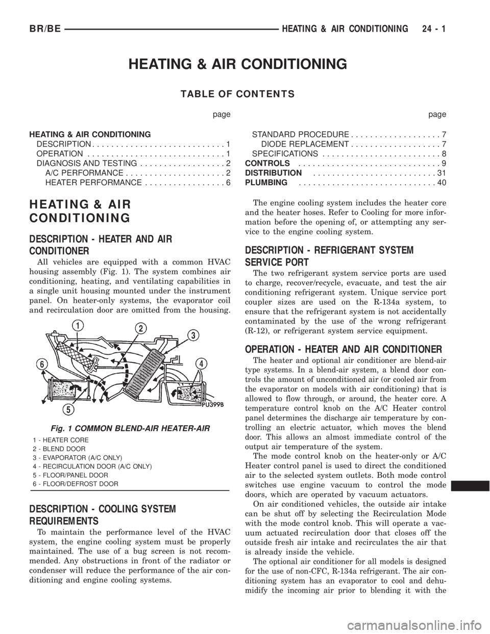
All vehicles are equipped with a common HVAC
housing assembly (Fig. 1). The system combines air
conditioning, heating, and ventilating capabilities in
a single unit housing mounted under the instrument
panel. On heater-only systems, the evaporator coil
and recirculation door are omitted from the housing.
DESCRIPTION - COOLING SYSTEM
REQUIREMENTS
To maintain the performance level of the HVAC
system, the engine cooling system must be properly
maintained. The use of a bug screen is not recom-
mended. Any obstructions in front of the radiator or
condenser will reduce the performance of the air con-
ditioning and engine cooling systems.The engine cooling system includes the heater core
and the heater hoses. Refer to Cooling for more infor-
mation before the opening of, or attempting any ser-
vice to the engine cooling system.
DESCRIPTION - REFRIGERANT SYSTEM
SERVICE PORT
The two refrigerant system service ports are used
to charge, recover/recycle, evacuate, and test the air
conditioning refrigerant system. Unique service port
coupler sizes are used on the R-134a system, to
ensure that the refrigerant system is not accidentally
contaminated by the use of the wrong refrigerant
(R-12), or refrigerant system service equipment.
OPERATION - HEATER AND AIR CONDITIONER
The heater and optional air conditioner are blend-air
type systems. In a blend-air system, a blend door con-
trols the amount of unconditioned air (or cooled air from
the evaporator on models with air conditioning) that is
allowed to flow through, or around, the heater core. A
temperature control knob on the A/C Heater control
panel determines the discharge air temperature by con-
trolling an electric actuator, which moves the blend
door. This allows an almost immediate control of the
output air temperature of the system.
The mode control knob on the heater-only or A/C
Heater control panel is used to direct the conditioned
air to the selected system outlets. Both mode control
switches use engine vacuum to control the mode
doors, which are operated by vacuum actuators.
On air conditioned vehicles, the outside air intake
can be shut off by selecting the Recirculation Mode
with the mode control knob. This will operate a vac-
uum actuated recirculation door that closes off the
outside fresh air intake and recirculates the air that
is already inside the vehicle.
The optional air conditioner for all models is designed
for the use of non-CFC, R-134a refrigerant. The air con-
ditioning system has an evaporator to cool and dehu-
midify the incoming air prior to blending it with the
Fig. 1 COMMON BLEND-AIR HEATER-AIR
1 - HEATER CORE
2 - BLEND DOOR
3 - EVAPORATOR (A/C ONLY)
4 - RECIRCULATION DOOR (A/C ONLY)
5 - FLOOR/PANEL DOOR
6 - FLOOR/DEFROST DOOR
BR/BEHEATING & AIR CONDITIONING 24 - 1
Page 2731 of 2889
heated air. This air conditioning system uses a fixed ori-
fice tube in the middle of the liquid line to meter refrig-
erant flow to the evaporator coil. To maintain minimum
evaporator temperature and prevent evaporator freez-
ing, the a/c low pressure switch on the accumulator
cycles the compressor clutch.
OPERATION - REFRIGERANT SYSTEM SERVICE
PORT
The high pressure service port is located on the liq-
uid line between the condenser and the evaporator,
near the front of the engine compartment. The low
pressure service port is located on the suction line,
near the accumulator outlet.
Each of the service ports has a threaded plastic
protective cap installed over it from the factory. After
servicing the refrigerant system, always reinstall
both of the service port caps.
DIAGNOSIS AND TESTING - A/C
PERFORMANCE
The air conditioning system is designed to provide
the passenger compartment with low temperature
and low humidity air. The evaporator, located in the
HVAC housing on the dash panel below the instru-
ment panel, is cooled to temperatures near the freez-
ing point. As warm damp air passes through the
cooled evaporator, the air transfers its heat to the
refrigerant in the evaporator tubes and the moisture
in the air condenses on the evaporator fins. During
periods of high heat and humidity, an air condition-
ing system will be more effective in the recirculation
mode (Max-A/C). With the system in the recirculation
mode, only air from the passenger compartment
passes through the evaporator. As the passenger com-
partment air dehumidifies, the air conditioning sys-
tem performance levels improve.
Humidity has an important bearing on the temper-
ature of the air delivered to the interior of the vehi-
cle. It is important to understand the effect that
humidity has on the performance of the air condition-
ing system. When humidity is high, the evaporator
has to perform a double duty. It must lower the air
temperature, and it must lower the temperature of
the moisture in the air that condenses on the evapo-
rator fins. Condensing the moisture in the air trans-
fers heat energy into the evaporator fins and tubing.
This reduces the amount of heat the evaporator can
absorb from the air. High humidity greatly reduces
the ability of the evaporator to lower the temperature
of the air.
However, evaporator capacity used to reduce the
amount of moisture in the air is not wasted. Wring-
ing some of the moisture out of the air entering the
vehicle adds to the comfort of the passengers.
Although, an owner may expect too much from theirair conditioning system on humid days. A perfor-
mance test is the best way to determine whether the
system is performing up to standard. This test also
provides valuable clues as to the possible cause of
trouble with the air conditioning system.
Before proceeding, (Refer to 24 - HEATING & AIR
CONDITIONING/PLUMBING - WARNING) and
(Refer to 24 - HEATING & AIR CONDITIONING/
PLUMBING - CAUTION). The air temperature in
the test room and in the vehicle must be a minimum
of 21É C (70É F) for this test.
(1)
Connect a tachometer and a manifold gauge set.
(2) Set the a/c heater mode control switch knob to
the recirculation mode (Max-A/C) position, the tem-
perature control knob to the full cool position, and
the blower motor switch to the highest speed posi-
tion.
(3) Start the engine and hold the idle speed at
1,000 rpm with the compressor clutch engaged. If the
compressor clutch does not engage, (Refer to 24 -
HEATING & AIR CONDITIONING/CONTROLS/A/C
COMPRESSOR CLUTCH COIL - DIAGNOSIS AND
TESTING).
(4) The engine should be at operating temperature.
The doors and windows must be closed and the hood
must be mostly closed.
(5)
Insert a thermometer in the driver side center
A/C (panel) outlet. Operate the engine for five minutes.
(6) The compressor clutch may cycle, depending
upon the ambient temperature and humidity. If the
clutch cycles, unplug the a/c low pressure switch wire
harness connector from the switch located on the
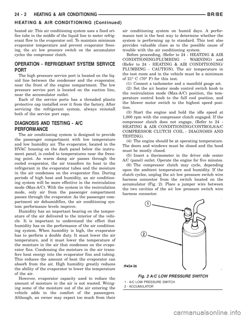
accumulator (Fig. 2). Place a jumper wire between
the two cavities of the a/c low pressure switch wire
harness connector.
Fig. 2 A/C LOW PRESSURE SWITCH
1 - A/C LOW PRESSURE SWITCH
2 - ACCUMULATOR
24 - 2 HEATING & AIR CONDITIONINGBR/BE
HEATING & AIR CONDITIONING (Continued)
Page 2732 of 2889
(7)With the compressor clutch engaged, record the
panel outlet discharge air temperature, the discharge
pressure (high side), and the suction pressure (low side).
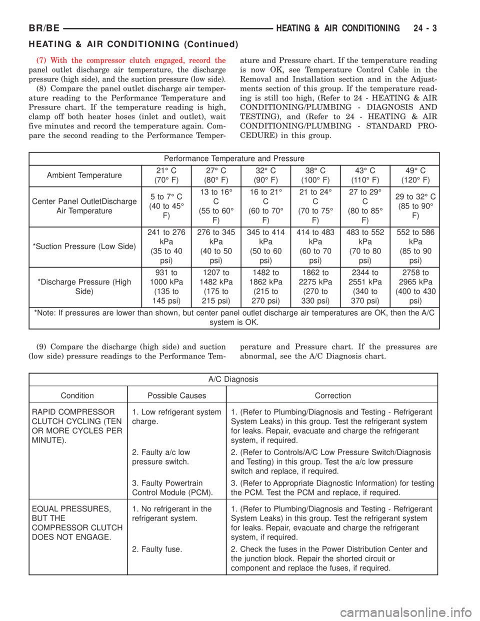
(8) Compare the panel outlet discharge air temper-
ature reading to the Performance Temperature and
Pressure chart. If the temperature reading is high,
clamp off both heater hoses (inlet and outlet), wait
five minutes and record the temperature again. Com-
pare the second reading to the Performance Temper-ature and Pressure chart. If the temperature reading
is now OK, see Temperature Control Cable in the
Removal and Installation section and in the Adjust-
ments section of this group. If the temperature read-
ing is still too high, (Refer to 24 - HEATING & AIR
CONDITIONING/PLUMBING - DIAGNOSIS AND
TESTING), and (Refer to 24 - HEATING & AIR
CONDITIONING/PLUMBING - STANDARD PRO-
CEDURE) in this group.
Performance Temperature and Pressure
Ambient Temperature21É C
(70É F)27É C
(80É F)32É C
(90É F)38É C
(100É F)43É C
(110É F)49É C
(120É F)
Center Panel OutletDischarge
Air Temperature5to7ÉC
(40 to 45É
F)13 to 16É
C
(55 to 60É
F)16 to 21É
C
(60 to 70É
F)21 to 24É
C
(70 to 75É
F)27 to 29É
C
(80 to 85É
F)29 to 32É C
(85 to 90É
F)
*Suction Pressure (Low Side)241 to 276
kPa
(35 to 40
psi)276 to 345
kPa
(40 to 50
psi)345 to 414
kPa
(50 to 60
psi)414 to 483
kPa
(60 to 70
psi)483 to 552
kPa
(70 to 80
psi)552 to 586
kPa
(85 to 90
psi)
*Discharge Pressure (High
Side)931 to
1000 kPa
(135 to
145 psi)1207 to
1482 kPa
(175 to
215 psi)1482 to
1862 kPa
(215 to
270 psi)1862 to
2275 kPa
(270 to
330 psi)2344 to
2551 kPa
(340 to
370 psi)2758 to
2965 kPa
(400 to 430
psi)
*Note: If pressures are lower than shown, but center panel outlet discharge air temperatures are OK, then the A/C
system is OK.
(9) Compare the discharge (high side) and suction
(low side) pressure readings to the Performance Tem-perature and Pressure chart. If the pressures are
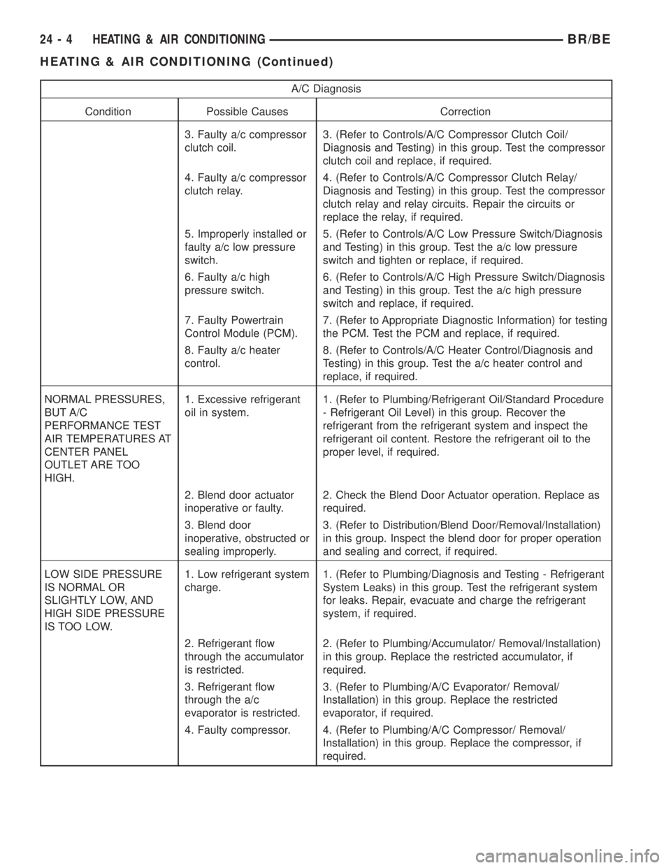
abnormal, see the A/C Diagnosis chart.
A/C Diagnosis
Condition Possible Causes Correction
RAPID COMPRESSOR
CLUTCH CYCLING (TEN
OR MORE CYCLES PER
MINUTE).1. Low refrigerant system
charge.1. (Refer to Plumbing/Diagnosis and Testing - Refrigerant
System Leaks) in this group. Test the refrigerant system
for leaks. Repair, evacuate and charge the refrigerant
system, if required.
2. Faulty a/c low
pressure switch.2. (Refer to Controls/A/C Low Pressure Switch/Diagnosis
and Testing) in this group. Test the a/c low pressure
switch and replace, if required.
3. Faulty Powertrain
Control Module (PCM).3. (Refer to Appropriate Diagnostic Information) for testing
the PCM. Test the PCM and replace, if required.
EQUAL PRESSURES,
BUT THE
COMPRESSOR CLUTCH
DOES NOT ENGAGE.1. No refrigerant in the
refrigerant system.1. (Refer to Plumbing/Diagnosis and Testing - Refrigerant
System Leaks) in this group. Test the refrigerant system
for leaks. Repair, evacuate and charge the refrigerant
system, if required.
2. Faulty fuse. 2. Check the fuses in the Power Distribution Center and
the junction block. Repair the shorted circuit or
component and replace the fuses, if required.
BR/BEHEATING & AIR CONDITIONING 24 - 3
HEATING & AIR CONDITIONING (Continued)
Page 2733 of 2889
A/C Diagnosis
Condition Possible Causes Correction
3. Faulty a/c compressor
clutch coil.3. (Refer to Controls/A/C Compressor Clutch Coil/
Diagnosis and Testing) in this group. Test the compressor
clutch coil and replace, if required.
4. Faulty a/c compressor
clutch relay.4. (Refer to Controls/A/C Compressor Clutch Relay/
Diagnosis and Testing) in this group. Test the compressor
clutch relay and relay circuits. Repair the circuits or
replace the relay, if required.
5. Improperly installed or
faulty a/c low pressure
switch.5. (Refer to Controls/A/C Low Pressure Switch/Diagnosis
and Testing) in this group. Test the a/c low pressure
switch and tighten or replace, if required.
6. Faulty a/c high
pressure switch.6. (Refer to Controls/A/C High Pressure Switch/Diagnosis
and Testing) in this group. Test the a/c high pressure
switch and replace, if required.
7. Faulty Powertrain
Control Module (PCM).7. (Refer to Appropriate Diagnostic Information) for testing
the PCM. Test the PCM and replace, if required.
8. Faulty a/c heater
control.8. (Refer to Controls/A/C Heater Control/Diagnosis and
Testing) in this group. Test the a/c heater control and
replace, if required.
NORMAL PRESSURES,
BUT A/C
PERFORMANCE TEST
AIR TEMPERATURES AT
CENTER PANEL
OUTLET ARE TOO
HIGH.1. Excessive refrigerant
oil in system.1. (Refer to Plumbing/Refrigerant Oil/Standard Procedure
- Refrigerant Oil Level) in this group. Recover the
refrigerant from the refrigerant system and inspect the
refrigerant oil content. Restore the refrigerant oil to the
proper level, if required.
2. Blend door actuator
inoperative or faulty.2. Check the Blend Door Actuator operation. Replace as
required.
3. Blend door
inoperative, obstructed or
sealing improperly.3. (Refer to Distribution/Blend Door/Removal/Installation)
in this group. Inspect the blend door for proper operation
and sealing and correct, if required.
LOW SIDE PRESSURE
IS NORMAL OR
SLIGHTLY LOW, AND
HIGH SIDE PRESSURE
IS TOO LOW.1. Low refrigerant system
charge.1. (Refer to Plumbing/Diagnosis and Testing - Refrigerant
System Leaks) in this group. Test the refrigerant system
for leaks. Repair, evacuate and charge the refrigerant
system, if required.
2. Refrigerant flow
through the accumulator
is restricted.2. (Refer to Plumbing/Accumulator/ Removal/Installation)
in this group. Replace the restricted accumulator, if
required.
3. Refrigerant flow
through the a/c
evaporator is restricted.3. (Refer to Plumbing/A/C Evaporator/ Removal/
Installation) in this group. Replace the restricted
evaporator, if required.
4. Faulty compressor. 4. (Refer to Plumbing/A/C Compressor/ Removal/
Installation) in this group. Replace the compressor, if
required.
24 - 4 HEATING & AIR CONDITIONINGBR/BE
HEATING & AIR CONDITIONING (Continued)