2001 DODGE RAM set clock
[x] Cancel search: set clockPage 1947 of 2889
SECOND GEAR POWERFLOW
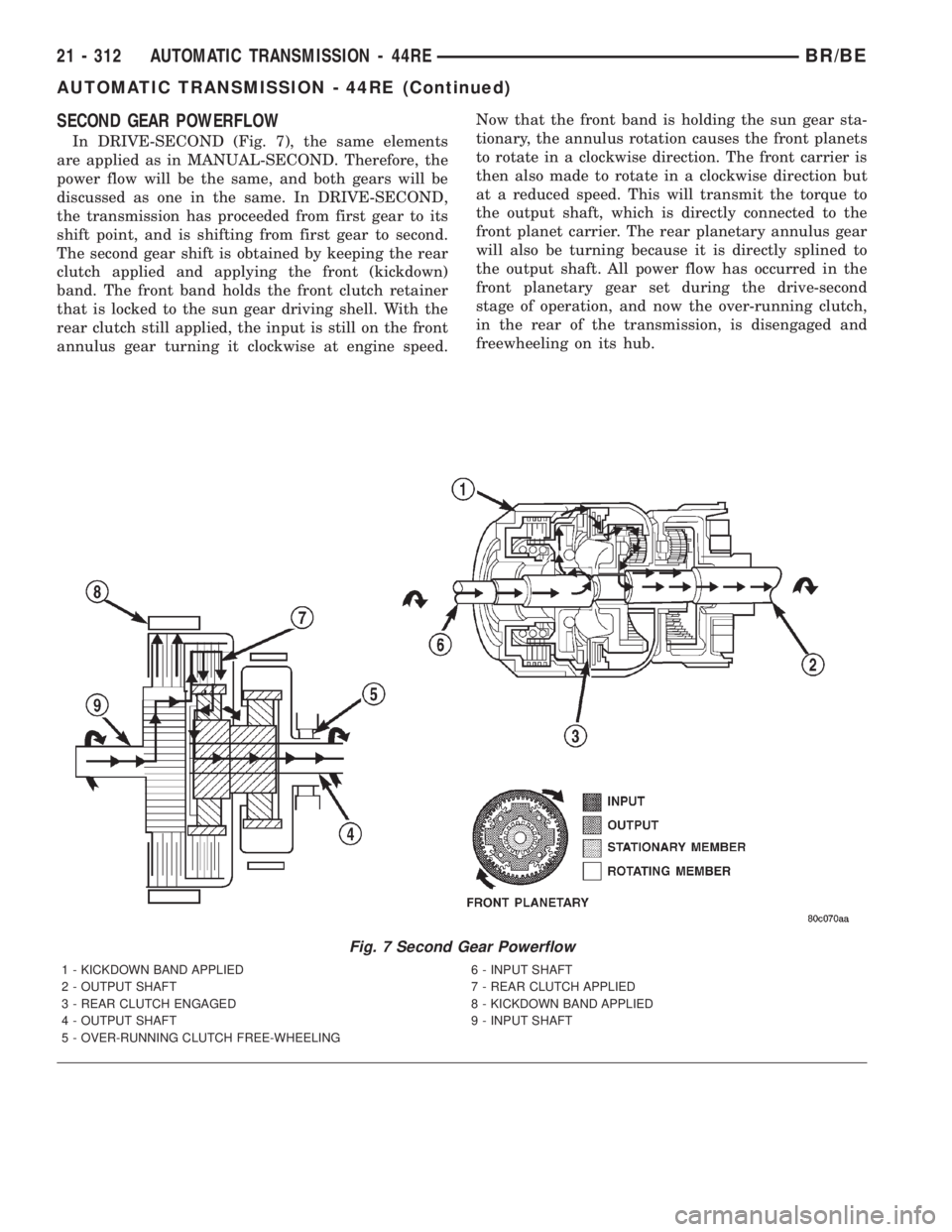
In DRIVE-SECOND (Fig. 7), the same elements
are applied as in MANUAL-SECOND. Therefore, the
power flow will be the same, and both gears will be
discussed as one in the same. In DRIVE-SECOND,
the transmission has proceeded from first gear to its
shift point, and is shifting from first gear to second.
The second gear shift is obtained by keeping the rear
clutch applied and applying the front (kickdown)
band. The front band holds the front clutch retainer
that is locked to the sun gear driving shell. With the
rear clutch still applied, the input is still on the front
annulus gear turning it clockwise at engine speed.Now that the front band is holding the sun gear sta-
tionary, the annulus rotation causes the front planets
to rotate in a clockwise direction. The front carrier is
then also made to rotate in a clockwise direction but
at a reduced speed. This will transmit the torque to
the output shaft, which is directly connected to the
front planet carrier. The rear planetary annulus gear
will also be turning because it is directly splined to
the output shaft. All power flow has occurred in the
front planetary gear set during the drive-second
stage of operation, and now the over-running clutch,
in the rear of the transmission, is disengaged and
freewheeling on its hub.
Fig. 7 Second Gear Powerflow
1 - KICKDOWN BAND APPLIED 6 - INPUT SHAFT
2 - OUTPUT SHAFT 7 - REAR CLUTCH APPLIED
3 - REAR CLUTCH ENGAGED 8 - KICKDOWN BAND APPLIED
4 - OUTPUT SHAFT 9 - INPUT SHAFT
5 - OVER-RUNNING CLUTCH FREE-WHEELING
21 - 312 AUTOMATIC TRANSMISSION - 44REBR/BE
AUTOMATIC TRANSMISSION - 44RE (Continued)
Page 1948 of 2889
DIRECT DRIVE POWERFLOW
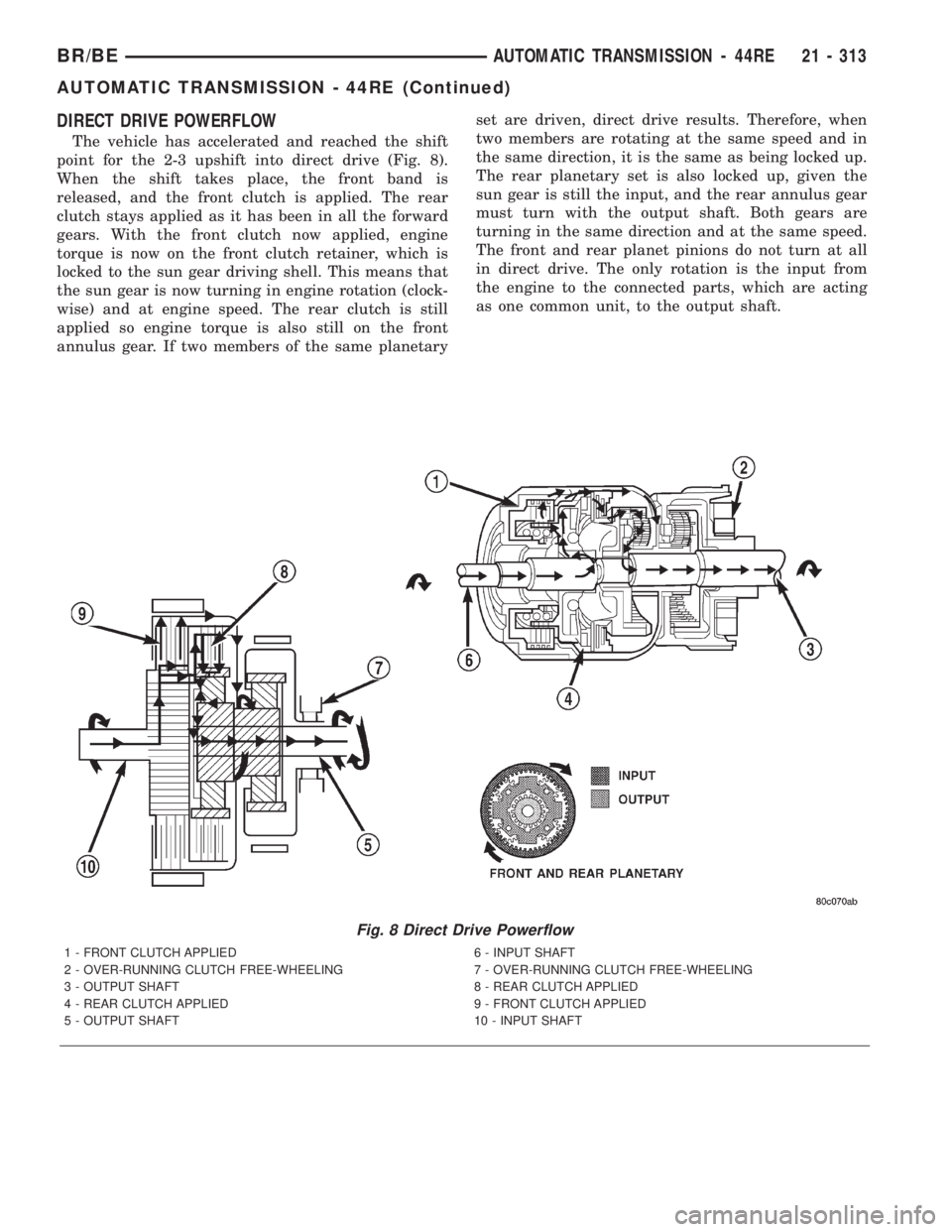
The vehicle has accelerated and reached the shift
point for the 2-3 upshift into direct drive (Fig. 8).
When the shift takes place, the front band is
released, and the front clutch is applied. The rear
clutch stays applied as it has been in all the forward
gears. With the front clutch now applied, engine
torque is now on the front clutch retainer, which is
locked to the sun gear driving shell. This means that
the sun gear is now turning in engine rotation (clock-
wise) and at engine speed. The rear clutch is still
applied so engine torque is also still on the front
annulus gear. If two members of the same planetaryset are driven, direct drive results. Therefore, when
two members are rotating at the same speed and in
the same direction, it is the same as being locked up.
The rear planetary set is also locked up, given the
sun gear is still the input, and the rear annulus gear
must turn with the output shaft. Both gears are
turning in the same direction and at the same speed.
The front and rear planet pinions do not turn at all
in direct drive. The only rotation is the input from
the engine to the connected parts, which are acting
as one common unit, to the output shaft.
Fig. 8 Direct Drive Powerflow
1 - FRONT CLUTCH APPLIED 6 - INPUT SHAFT
2 - OVER-RUNNING CLUTCH FREE-WHEELING 7 - OVER-RUNNING CLUTCH FREE-WHEELING
3 - OUTPUT SHAFT 8 - REAR CLUTCH APPLIED
4 - REAR CLUTCH APPLIED 9 - FRONT CLUTCH APPLIED
5 - OUTPUT SHAFT 10 - INPUT SHAFT
BR/BEAUTOMATIC TRANSMISSION - 44RE 21 - 313
AUTOMATIC TRANSMISSION - 44RE (Continued)
Page 2111 of 2889
ADJUSTMENTS - VALVE BODY
CONTROL PRESSURE ADJUSTMENTS
There are two control pressure adjustments on the
valve body;
²Line Pressure
²Throttle Pressure
Line and throttle pressures are interdependent
because each affects shift quality and timing. As a
result, both adjustments must be performed properly
and in the correct sequence. Adjust line pressure first
and throttle pressure last.
LINE PRESSURE ADJUSTMENT
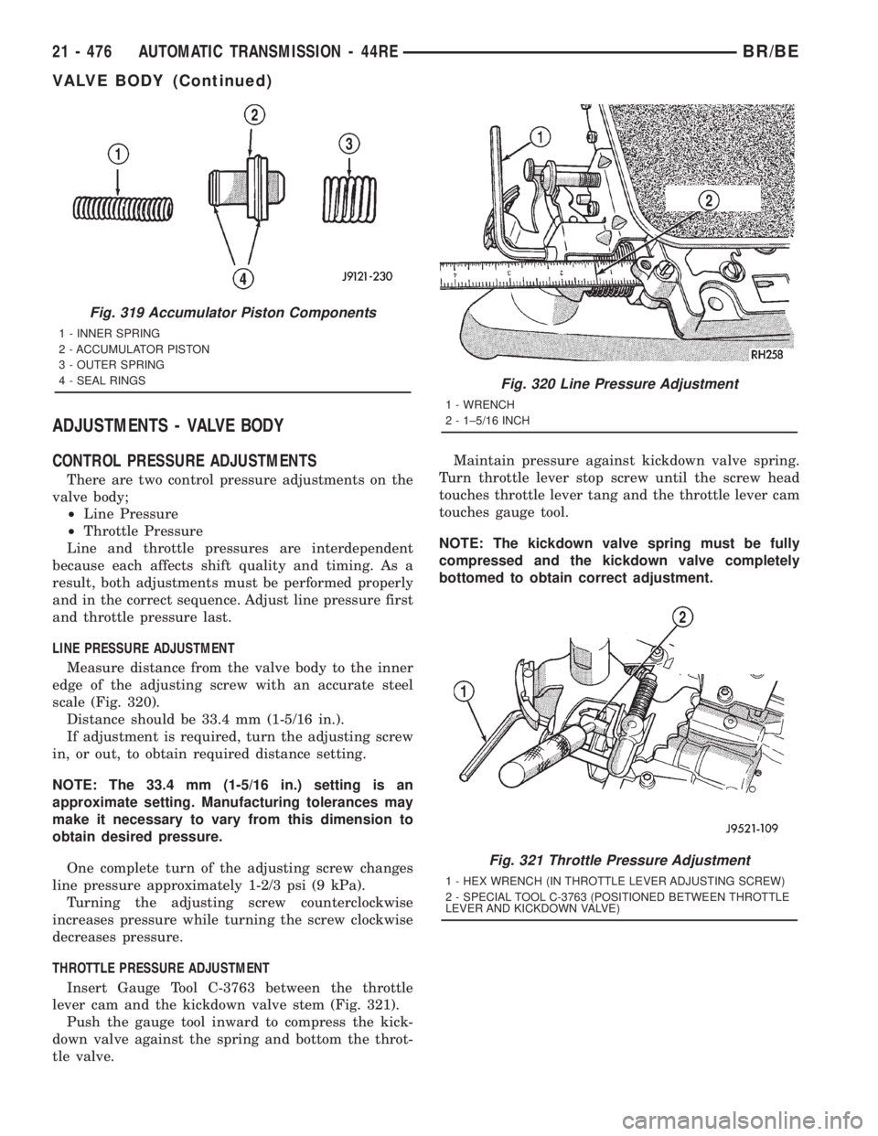
Measure distance from the valve body to the inner
edge of the adjusting screw with an accurate steel
scale (Fig. 320).
Distance should be 33.4 mm (1-5/16 in.).
If adjustment is required, turn the adjusting screw
in, or out, to obtain required distance setting.
NOTE: The 33.4 mm (1-5/16 in.) setting is an
approximate setting. Manufacturing tolerances may
make it necessary to vary from this dimension to
obtain desired pressure.
One complete turn of the adjusting screw changes
line pressure approximately 1-2/3 psi (9 kPa).
Turning the adjusting screw counterclockwise
increases pressure while turning the screw clockwise
decreases pressure.
THROTTLE PRESSURE ADJUSTMENT
Insert Gauge Tool C-3763 between the throttle
lever cam and the kickdown valve stem (Fig. 321).
Push the gauge tool inward to compress the kick-
down valve against the spring and bottom the throt-
tle valve.Maintain pressure against kickdown valve spring.
Turn throttle lever stop screw until the screw head
touches throttle lever tang and the throttle lever cam
touches gauge tool.
NOTE: The kickdown valve spring must be fully
compressed and the kickdown valve completely
bottomed to obtain correct adjustment.
Fig. 319 Accumulator Piston Components
1 - INNER SPRING
2 - ACCUMULATOR PISTON
3 - OUTER SPRING
4 - SEAL RINGS
Fig. 320 Line Pressure Adjustment
1 - WRENCH
2 - 1±5/16 INCH
Fig. 321 Throttle Pressure Adjustment
1 - HEX WRENCH (IN THROTTLE LEVER ADJUSTING SCREW)
2 - SPECIAL TOOL C-3763 (POSITIONED BETWEEN THROTTLE
LEVER AND KICKDOWN VALVE)
21 - 476 AUTOMATIC TRANSMISSION - 44REBR/BE
VALVE BODY (Continued)
Page 2117 of 2889
REVERSE POWERFLOW
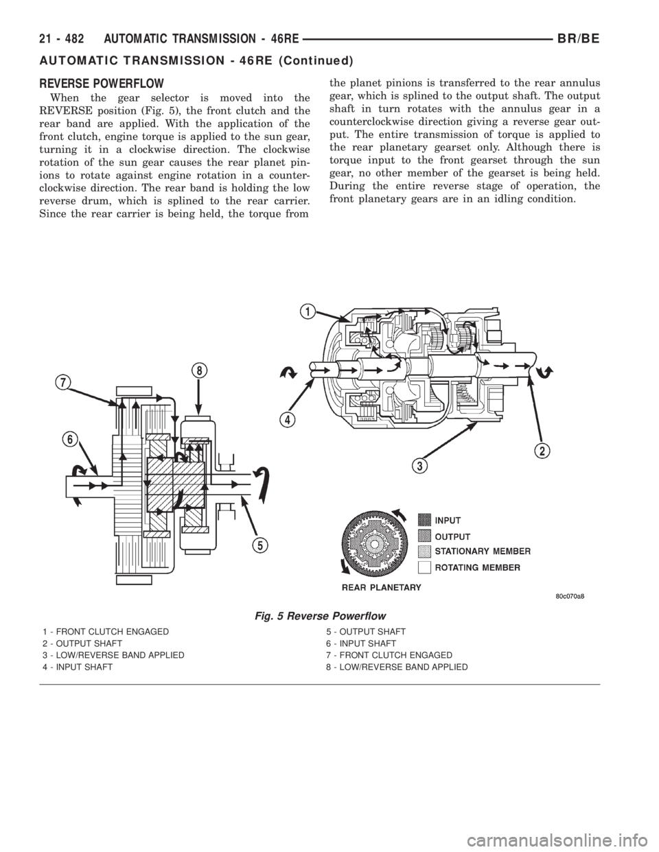
When the gear selector is moved into the
REVERSE position (Fig. 5), the front clutch and the
rear band are applied. With the application of the
front clutch, engine torque is applied to the sun gear,
turning it in a clockwise direction. The clockwise
rotation of the sun gear causes the rear planet pin-
ions to rotate against engine rotation in a counter-
clockwise direction. The rear band is holding the low
reverse drum, which is splined to the rear carrier.
Since the rear carrier is being held, the torque fromthe planet pinions is transferred to the rear annulus
gear, which is splined to the output shaft. The output
shaft in turn rotates with the annulus gear in a
counterclockwise direction giving a reverse gear out-
put. The entire transmission of torque is applied to
the rear planetary gearset only. Although there is
torque input to the front gearset through the sun
gear, no other member of the gearset is being held.
During the entire reverse stage of operation, the
front planetary gears are in an idling condition.
Fig. 5 Reverse Powerflow
1 - FRONT CLUTCH ENGAGED 5 - OUTPUT SHAFT
2 - OUTPUT SHAFT 6 - INPUT SHAFT
3 - LOW/REVERSE BAND APPLIED 7 - FRONT CLUTCH ENGAGED
4 - INPUT SHAFT 8 - LOW/REVERSE BAND APPLIED
21 - 482 AUTOMATIC TRANSMISSION - 46REBR/BE
AUTOMATIC TRANSMISSION - 46RE (Continued)
Page 2119 of 2889
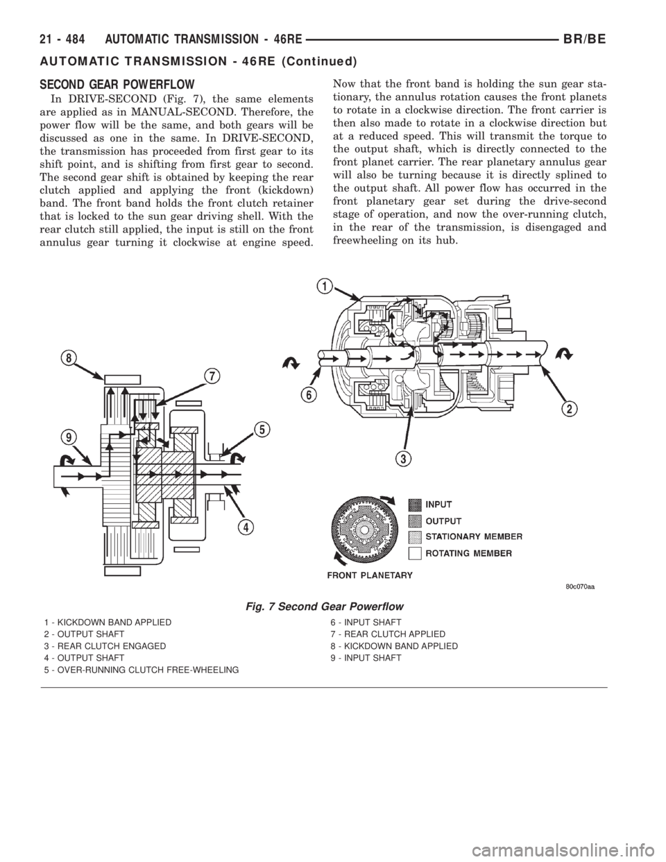
SECOND GEAR POWERFLOW
In DRIVE-SECOND (Fig. 7), the same elements
are applied as in MANUAL-SECOND. Therefore, the
power flow will be the same, and both gears will be
discussed as one in the same. In DRIVE-SECOND,
the transmission has proceeded from first gear to its
shift point, and is shifting from first gear to second.
The second gear shift is obtained by keeping the rear
clutch applied and applying the front (kickdown)
band. The front band holds the front clutch retainer
that is locked to the sun gear driving shell. With the
rear clutch still applied, the input is still on the front
annulus gear turning it clockwise at engine speed.Now that the front band is holding the sun gear sta-
tionary, the annulus rotation causes the front planets
to rotate in a clockwise direction. The front carrier is
then also made to rotate in a clockwise direction but
at a reduced speed. This will transmit the torque to
the output shaft, which is directly connected to the
front planet carrier. The rear planetary annulus gear
will also be turning because it is directly splined to
the output shaft. All power flow has occurred in the
front planetary gear set during the drive-second
stage of operation, and now the over-running clutch,
in the rear of the transmission, is disengaged and
freewheeling on its hub.
Fig. 7 Second Gear Powerflow
1 - KICKDOWN BAND APPLIED 6 - INPUT SHAFT
2 - OUTPUT SHAFT 7 - REAR CLUTCH APPLIED
3 - REAR CLUTCH ENGAGED 8 - KICKDOWN BAND APPLIED
4 - OUTPUT SHAFT 9 - INPUT SHAFT
5 - OVER-RUNNING CLUTCH FREE-WHEELING
21 - 484 AUTOMATIC TRANSMISSION - 46REBR/BE
AUTOMATIC TRANSMISSION - 46RE (Continued)
Page 2120 of 2889
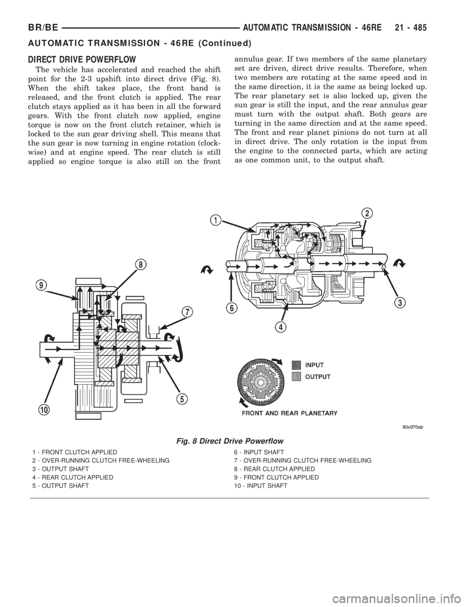
DIRECT DRIVE POWERFLOW
The vehicle has accelerated and reached the shift
point for the 2-3 upshift into direct drive (Fig. 8).
When the shift takes place, the front band is
released, and the front clutch is applied. The rear
clutch stays applied as it has been in all the forward
gears. With the front clutch now applied, engine
torque is now on the front clutch retainer, which is
locked to the sun gear driving shell. This means that
the sun gear is now turning in engine rotation (clock-
wise) and at engine speed. The rear clutch is still
applied so engine torque is also still on the frontannulus gear. If two members of the same planetary
set are driven, direct drive results. Therefore, when
two members are rotating at the same speed and in
the same direction, it is the same as being locked up.
The rear planetary set is also locked up, given the
sun gear is still the input, and the rear annulus gear
must turn with the output shaft. Both gears are
turning in the same direction and at the same speed.
The front and rear planet pinions do not turn at all
in direct drive. The only rotation is the input from
the engine to the connected parts, which are acting
as one common unit, to the output shaft.
Fig. 8 Direct Drive Powerflow
1 - FRONT CLUTCH APPLIED 6 - INPUT SHAFT
2 - OVER-RUNNING CLUTCH FREE-WHEELING 7 - OVER-RUNNING CLUTCH FREE-WHEELING
3 - OUTPUT SHAFT 8 - REAR CLUTCH APPLIED
4 - REAR CLUTCH APPLIED 9 - FRONT CLUTCH APPLIED
5 - OUTPUT SHAFT 10 - INPUT SHAFT
BR/BEAUTOMATIC TRANSMISSION - 46RE 21 - 485
AUTOMATIC TRANSMISSION - 46RE (Continued)
Page 2288 of 2889
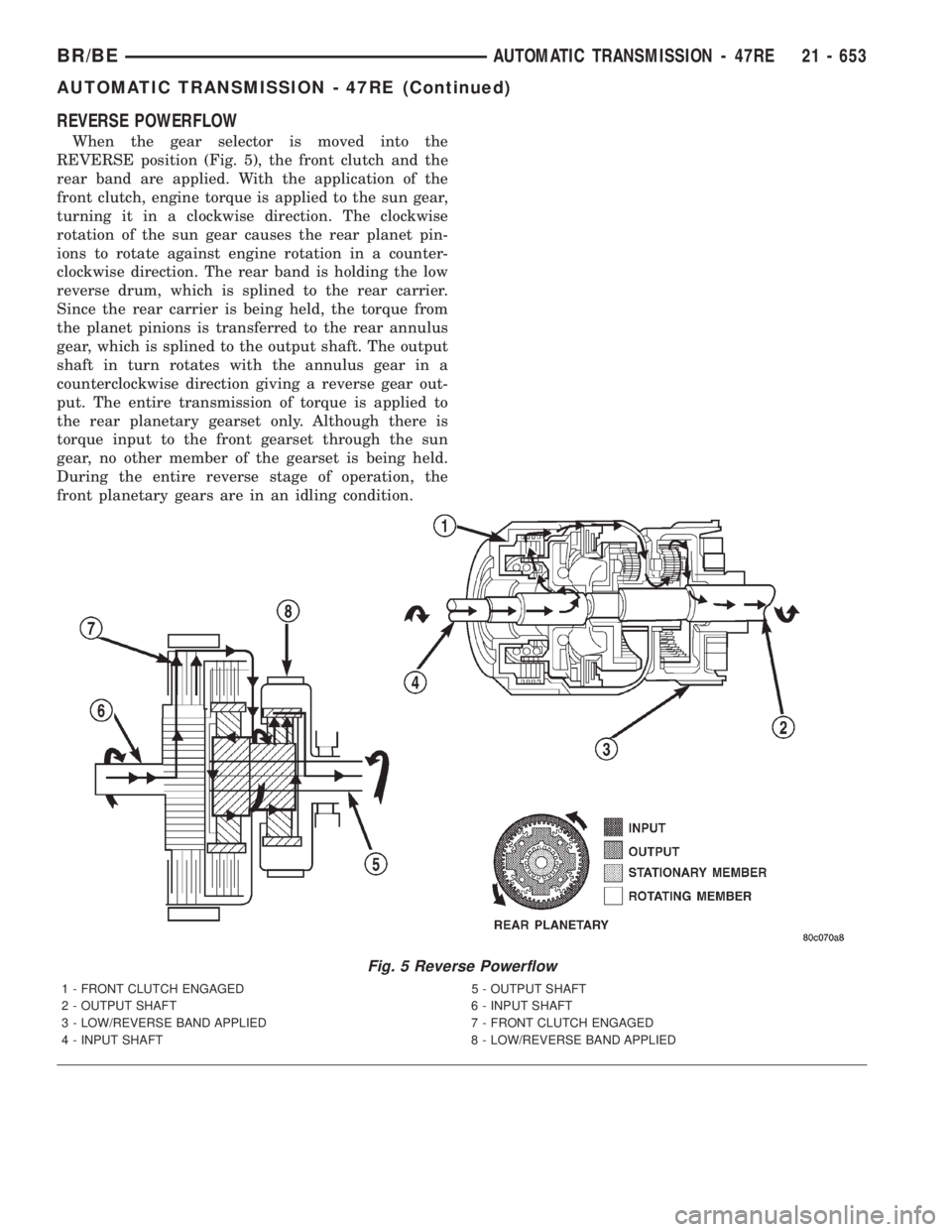
REVERSE POWERFLOW
When the gear selector is moved into the
REVERSE position (Fig. 5), the front clutch and the
rear band are applied. With the application of the
front clutch, engine torque is applied to the sun gear,
turning it in a clockwise direction. The clockwise
rotation of the sun gear causes the rear planet pin-
ions to rotate against engine rotation in a counter-
clockwise direction. The rear band is holding the low
reverse drum, which is splined to the rear carrier.
Since the rear carrier is being held, the torque from
the planet pinions is transferred to the rear annulus
gear, which is splined to the output shaft. The output
shaft in turn rotates with the annulus gear in a
counterclockwise direction giving a reverse gear out-
put. The entire transmission of torque is applied to
the rear planetary gearset only. Although there is
torque input to the front gearset through the sun
gear, no other member of the gearset is being held.
During the entire reverse stage of operation, the
front planetary gears are in an idling condition.
Fig. 5 Reverse Powerflow
1 - FRONT CLUTCH ENGAGED 5 - OUTPUT SHAFT
2 - OUTPUT SHAFT 6 - INPUT SHAFT
3 - LOW/REVERSE BAND APPLIED 7 - FRONT CLUTCH ENGAGED
4 - INPUT SHAFT 8 - LOW/REVERSE BAND APPLIED
BR/BEAUTOMATIC TRANSMISSION - 47RE 21 - 653
AUTOMATIC TRANSMISSION - 47RE (Continued)
Page 2290 of 2889
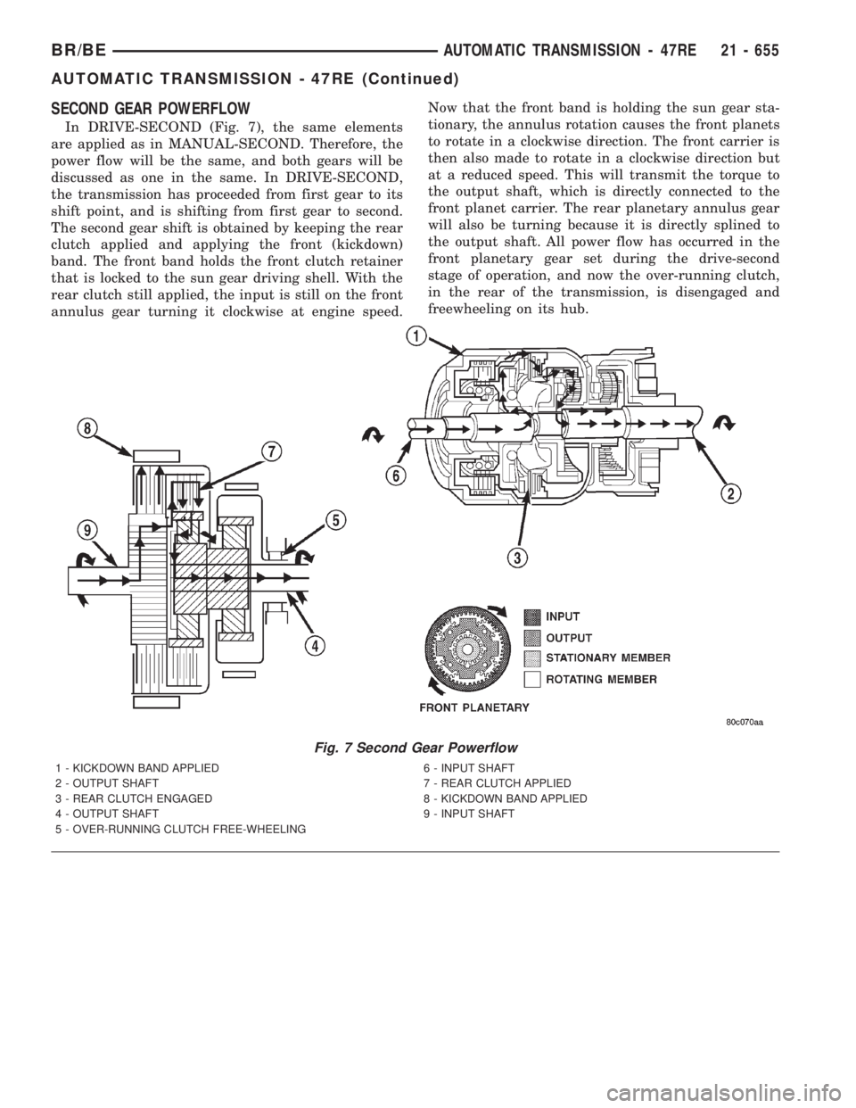
SECOND GEAR POWERFLOW
In DRIVE-SECOND (Fig. 7), the same elements
are applied as in MANUAL-SECOND. Therefore, the
power flow will be the same, and both gears will be
discussed as one in the same. In DRIVE-SECOND,
the transmission has proceeded from first gear to its
shift point, and is shifting from first gear to second.
The second gear shift is obtained by keeping the rear
clutch applied and applying the front (kickdown)
band. The front band holds the front clutch retainer
that is locked to the sun gear driving shell. With the
rear clutch still applied, the input is still on the front
annulus gear turning it clockwise at engine speed.Now that the front band is holding the sun gear sta-
tionary, the annulus rotation causes the front planets
to rotate in a clockwise direction. The front carrier is
then also made to rotate in a clockwise direction but
at a reduced speed. This will transmit the torque to
the output shaft, which is directly connected to the
front planet carrier. The rear planetary annulus gear
will also be turning because it is directly splined to
the output shaft. All power flow has occurred in the
front planetary gear set during the drive-second
stage of operation, and now the over-running clutch,
in the rear of the transmission, is disengaged and
freewheeling on its hub.
Fig. 7 Second Gear Powerflow
1 - KICKDOWN BAND APPLIED 6 - INPUT SHAFT
2 - OUTPUT SHAFT 7 - REAR CLUTCH APPLIED
3 - REAR CLUTCH ENGAGED 8 - KICKDOWN BAND APPLIED
4 - OUTPUT SHAFT 9 - INPUT SHAFT
5 - OVER-RUNNING CLUTCH FREE-WHEELING
BR/BEAUTOMATIC TRANSMISSION - 47RE 21 - 655
AUTOMATIC TRANSMISSION - 47RE (Continued)