2001 DODGE RAM set clock
[x] Cancel search: set clockPage 549 of 2889

removed). Then continue to slowly rotate engine
clockwise until indicating mark (Fig. 18) is aligned to
0 degree (TDC) mark on timing chain cover.
(1) Clean top of cylinder block for a good seal
between distributor base and block.
(2) Lightly oil the rubber o-ring seal on the distrib-
utor housing.
(3) Install rotor to distributor shaft.
(4) Position distributor into engine to its original
position. Engage tongue of distributor shaft with slot
in distributor oil pump drive gear. Position rotor to
the number one spark plug cable position.
(5) Install distributor holddown clamp and clamp
bolt. Do not tighten bolt at this time.(6) Rotate the distributor housing until rotor is
aligned to CYL. NO. 1 alignment mark on the cam-
shaft position sensor (Fig. 19) .
(7) Tighten clamp holddown bolt (Fig. 20) to 22.5
N´m (200 in. lbs.) torque.
(8) Connect camshaft position sensor wiring har-
ness to main engine harness.
(9) Install distributor cap. Tighten mounting
screws.
(10) Refer to the following, Checking Distributor
Position.
Checking Distributor Position
To verify correct distributor rotational position, the
DRB scan tool must be used.
WARNING: WHEN PERFORMING THE FOLLOWING
TEST, THE ENGINE WILL BE RUNNING. BE CARE-
FUL NOT TO STAND IN LINE WITH THE FAN
BLADES OR FAN BELT. DO NOT WEAR LOOSE
CLOTHING.
(1) Connect DRB scan tool to data link connector.
The data link connector is located in passenger com-
partment, below and to left of steering column.
(2) Gain access to SET SYNC screen on DRB.
(3) Follow directions on DRB screen and start
engine. Bring to operating temperature (engine must
be in ªclosed loopº mode).
(4) With engine running atidle speed, the words
IN RANGE should appear on screen along with 0É.
This indicates correct distributor position.
(5) If a plus (+) or a minus (-) is displayed next to
degree number, and/or the degree displayed is not
zero, loosen but do not remove distributor holddown
clamp bolt. Rotate distributor until IN RANGE
appears on screen. Continue to rotate distributor
until achieving as close to 0É as possible. After
adjustment, tighten clamp bolt to 22.5 N´m (200 in.
lbs.) torque.
The degree scale on SET SYNC screen of DRB is
referring to fuel synchronization only.It is not
referring to ignition timing.Because of this, do
not attempt to adjust ignition timing using this
method. Rotating distributor will have no effect on
ignition timing. All ignition timing values are con-
trolled by powertrain control module (PCM).
After testing, install air cleaner assembly.
DISTRIBUTOR CAP
DIAGNOSIS AND TESTING - DISTRIBUTOR
CAP
Remove the distributor cap and wipe it clean with
a dry lint free cloth. Visually inspect the cap for
cracks, carbon paths, broken towers or damaged
Fig. 19 Rotor Alignment Mark
1 - CAMSHAFT POSITION SENSOR ALIGNMENT MARK
2 - ROTOR
3 - DISTRIBUTOR
Fig. 20 Distributor Holddown Clamp
1 - CLAMP BOLT
2 - HOLDDOWN CLAMP
3 - DISTRIBUTOR HOUSING
8I - 12 IGNITION CONTROLBR/BE
DISTRIBUTOR (Continued)
Page 602 of 2889
causing the PCM's output brake signal to go high,
disengaging the speed control, cutting off PCM power
to the speed control solenoids.
The second set of normally closed contacts supplies
12 volts from the PCM any time speed control is
turned on. Through the brake switch, current is
routed to the speed control servo solenoids. The
speed control solenoids (vacuum, vent and dump) are
provided this current any time the speed control is
ON and the brakes are disengaged.
When the driver applies the brakes, the contacts
open and current is interrupted to the solenoids. The
normally open contacts are fed battery voltage. When
the brakes are applied, battery voltage is supplied to
the brake lamps.
DIAGNOSIS AND TESTING - BRAKE LAMP
SWITCH
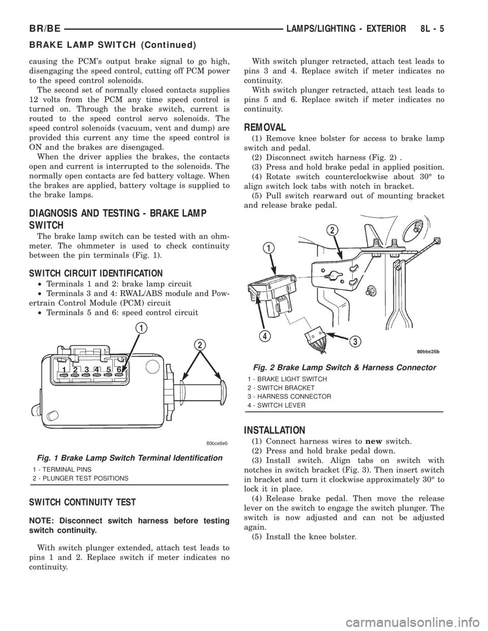
The brake lamp switch can be tested with an ohm-
meter. The ohmmeter is used to check continuity
between the pin terminals (Fig. 1).
SWITCH CIRCUIT IDENTIFICATION
²Terminals 1 and 2: brake lamp circuit
²Terminals 3 and 4: RWAL/ABS module and Pow-
ertrain Control Module (PCM) circuit
²Terminals 5 and 6: speed control circuit
SWITCH CONTINUITY TEST
NOTE: Disconnect switch harness before testing
switch continuity.
With switch plunger extended, attach test leads to
pins 1 and 2. Replace switch if meter indicates no
continuity.With switch plunger retracted, attach test leads to
pins 3 and 4. Replace switch if meter indicates no
continuity.
With switch plunger retracted, attach test leads to
pins 5 and 6. Replace switch if meter indicates no
continuity.
REMOVAL
(1) Remove knee bolster for access to brake lamp
switch and pedal.
(2) Disconnect switch harness (Fig. 2) .
(3) Press and hold brake pedal in applied position.
(4) Rotate switch counterclockwise about 30É to
align switch lock tabs with notch in bracket.
(5) Pull switch rearward out of mounting bracket
and release brake pedal.
INSTALLATION
(1) Connect harness wires tonewswitch.
(2) Press and hold brake pedal down.
(3) Install switch. Align tabs on switch with
notches in switch bracket (Fig. 3). Then insert switch
in bracket and turn it clockwise approximately 30É to
lock it in place.
(4) Release brake pedal. Then move the release
lever on the switch to engage the switch plunger. The
switch is now adjusted and can not be adjusted
again.
(5) Install the knee bolster.
Fig. 1 Brake Lamp Switch Terminal Identification
1 - TERMINAL PINS
2 - PLUNGER TEST POSITIONS
Fig. 2 Brake Lamp Switch & Harness Connector
1 - BRAKE LIGHT SWITCH
2 - SWITCH BRACKET
3 - HARNESS CONNECTOR
4 - SWITCH LEVER
BR/BELAMPS/LIGHTING - EXTERIOR 8L - 5
BRAKE LAMP SWITCH (Continued)
Page 661 of 2889
REMOVAL
(1) Disconnect and isolate the battery negative
cable.
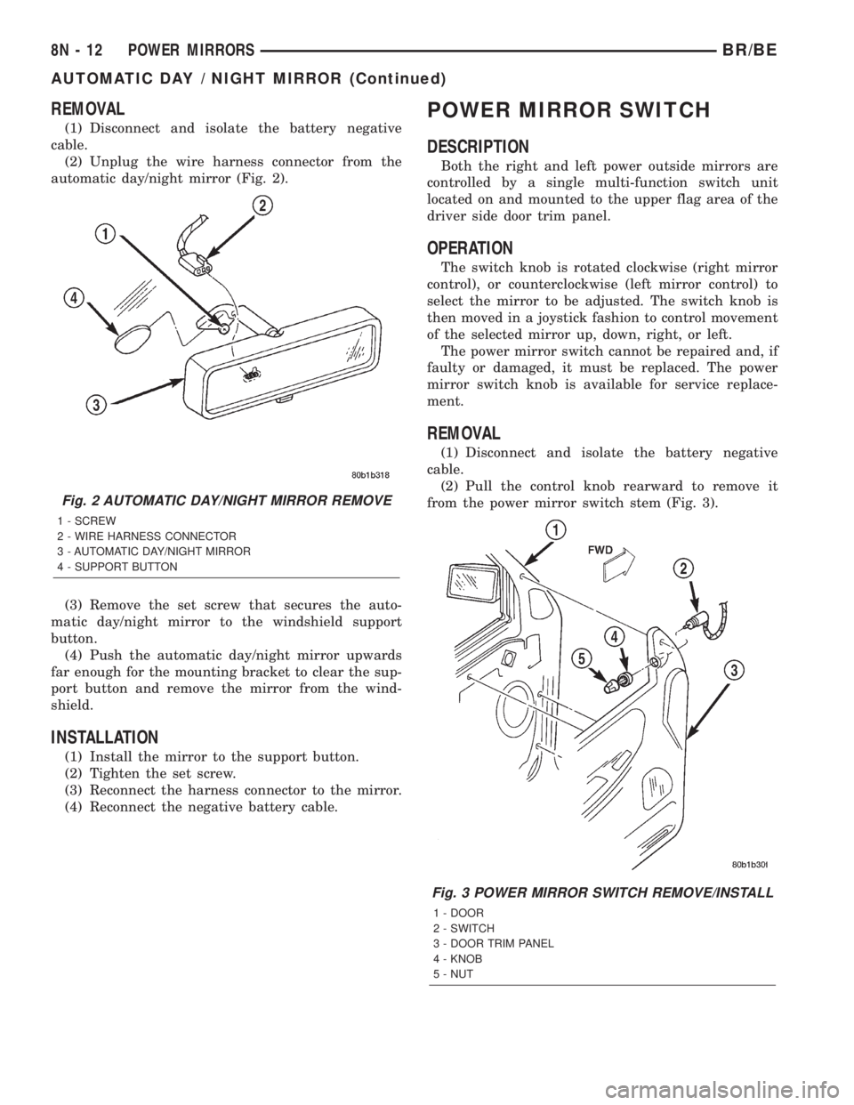
(2) Unplug the wire harness connector from the
automatic day/night mirror (Fig. 2).
(3) Remove the set screw that secures the auto-
matic day/night mirror to the windshield support
button.
(4) Push the automatic day/night mirror upwards
far enough for the mounting bracket to clear the sup-
port button and remove the mirror from the wind-
shield.
INSTALLATION
(1) Install the mirror to the support button.
(2) Tighten the set screw.
(3) Reconnect the harness connector to the mirror.
(4) Reconnect the negative battery cable.
POWER MIRROR SWITCH
DESCRIPTION
Both the right and left power outside mirrors are
controlled by a single multi-function switch unit
located on and mounted to the upper flag area of the
driver side door trim panel.
OPERATION
The switch knob is rotated clockwise (right mirror
control), or counterclockwise (left mirror control) to
select the mirror to be adjusted. The switch knob is
then moved in a joystick fashion to control movement
of the selected mirror up, down, right, or left.
The power mirror switch cannot be repaired and, if
faulty or damaged, it must be replaced. The power
mirror switch knob is available for service replace-
ment.
REMOVAL
(1) Disconnect and isolate the battery negative
cable.
(2) Pull the control knob rearward to remove it
from the power mirror switch stem (Fig. 3).
Fig. 2 AUTOMATIC DAY/NIGHT MIRROR REMOVE
1 - SCREW
2 - WIRE HARNESS CONNECTOR
3 - AUTOMATIC DAY/NIGHT MIRROR
4 - SUPPORT BUTTON
Fig. 3 POWER MIRROR SWITCH REMOVE/INSTALL
1 - DOOR
2 - SWITCH
3 - DOOR TRIM PANEL
4 - KNOB
5 - NUT
8N - 12 POWER MIRRORSBR/BE
AUTOMATIC DAY / NIGHT MIRROR (Continued)
Page 1185 of 2889
HYDRAULIC LIFTERS (CAM IN
BLOCK)
DIAGNOSIS AND TESTINGÐHYDRAULIC
TAPPETS
Before disassembling any part of the engine to cor-
rect tappet noise, check the oil pressure. If vehicle
has no oil pressure gauge, install a reliable gauge at
the pressure sending-unit. The pressure should be
between 207-552 kPa (30-80 psi) at 3,000 RPM.
Check the oil level after the engine reaches normal
operating temperature. Allow 5 minutes to stabilize
oil level, check dipstick. The oil level in the pan
should never be above the FULL mark or below the
ADD OIL mark on dipstick. Either of these two con-
ditions could be responsible for noisy tappets.
OIL LEVEL
HIGH
If oil level is above the FULL mark, it is possible
for the connecting rods to dip into the oil. With the
engine running, this condition could create foam in
the oil pan. Foam in oil pan would be fed to the
hydraulic tappets by the oil pump causing them to
lose length and allow valves to seat noisily.
LOW
Low oil level may allow oil pump to take in air.
When air is fed to the tappets, they lose length,
which allows valves to seat noisily. Any leaks on
intake side of oil pump through which air can be
drawn will create the same tappet action. Check the
lubrication system from the intake strainer to the
pump cover, including the relief valve retainer cap.
When tappet noise is due to aeration, it may be
intermittent or constant, and usually more than one
tappet will be noisy. When oil level and leaks have
been corrected, operate the engine at fast idle. Run
engine for a sufficient time to allow all of the air
inside the tappets to be bled out.
TAPPET NOISE DIAGNOSIS
(1) To determine source of tappet noise, operate
engine at idle with cylinder head covers removed.
(2) Feel each valve spring or rocker arm to detect
noisy tappet. The noisy tappet will cause the affected
spring and/or rocker arm to vibrate or feel rough in
operation.
NOTE: Worn valve guides or cocked springs are
sometimes mistaken for noisy tappets. If such is
the case, noise may be dampened by applying side
thrust on the valve spring. If noise is not apprecia-
bly reduced, it can be assumed the noise is in thetappet. Inspect the rocker arm push rod sockets
and push rod ends for wear.
(3) Valve tappet noise ranges from light noise to a
heavy click. A light noise is usually caused by exces-
sive leak-down around the unit plunger, or by the
plunger partially sticking in the tappet body cylinder.
The tappet should be replaced. A heavy click is
caused by a tappet check valve not seating, or by for-
eign particles wedged between the plunger and the
tappet body. This will cause the plunger to stick in
the down position. This heavy click will be accompa-
nied by excessive clearance between the valve stem
and rocker arm as valve closes. In either case, tappet
assembly should be removed for inspection and clean-
ing.
(4) The valve train generates a noise very much
like a light tappet noise during normal operation.
Care must be taken to ensure that tappets are mak-
ing the noise. If more than one tappet seems to be
noisy, it's probably not the tappets.
LEAK-DOWN TEST
After cleaning and inspection, test each tappet for
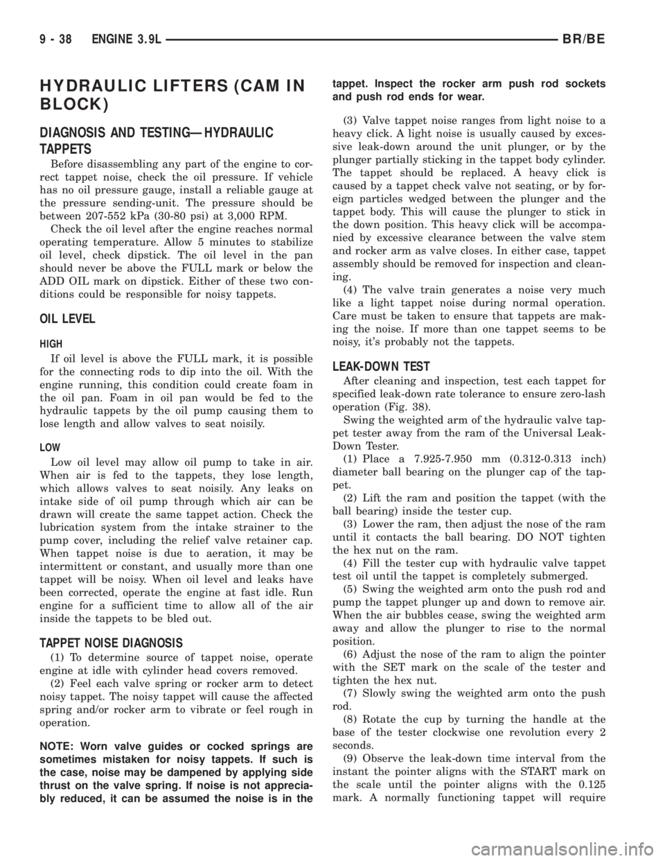
specified leak-down rate tolerance to ensure zero-lash
operation (Fig. 38).
Swing the weighted arm of the hydraulic valve tap-
pet tester away from the ram of the Universal Leak-
Down Tester.
(1) Place a 7.925-7.950 mm (0.312-0.313 inch)
diameter ball bearing on the plunger cap of the tap-
pet.
(2) Lift the ram and position the tappet (with the
ball bearing) inside the tester cup.
(3) Lower the ram, then adjust the nose of the ram
until it contacts the ball bearing. DO NOT tighten
the hex nut on the ram.
(4) Fill the tester cup with hydraulic valve tappet
test oil until the tappet is completely submerged.
(5) Swing the weighted arm onto the push rod and
pump the tappet plunger up and down to remove air.
When the air bubbles cease, swing the weighted arm
away and allow the plunger to rise to the normal
position.
(6) Adjust the nose of the ram to align the pointer
with the SET mark on the scale of the tester and
tighten the hex nut.
(7) Slowly swing the weighted arm onto the push
rod.
(8) Rotate the cup by turning the handle at the
base of the tester clockwise one revolution every 2
seconds.
(9) Observe the leak-down time interval from the
instant the pointer aligns with the START mark on
the scale until the pointer aligns with the 0.125
mark. A normally functioning tappet will require
9 - 38 ENGINE 3.9LBR/BE
Page 1189 of 2889
lower rails. Insert oil rail spacer first, then side
rails.
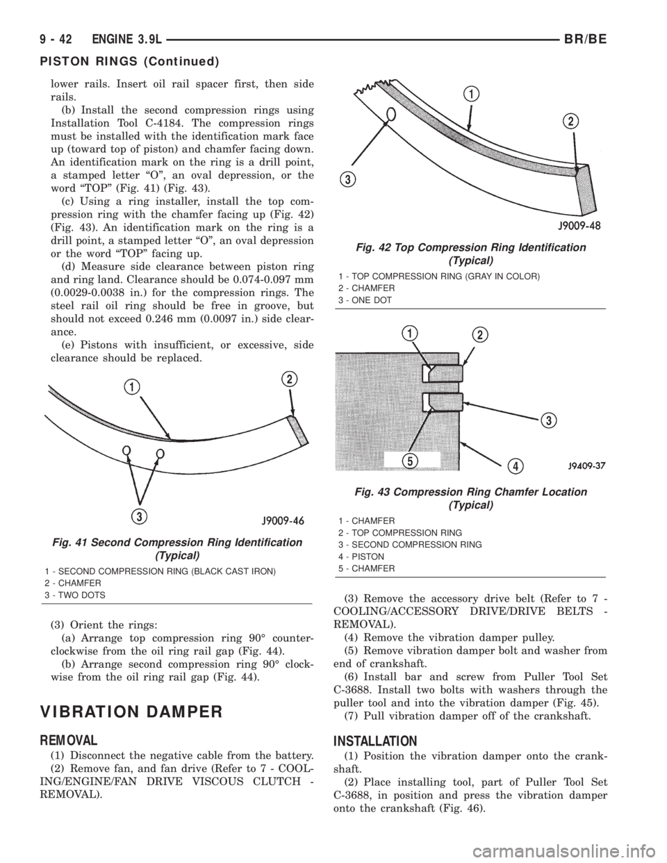
(b) Install the second compression rings using
Installation Tool C-4184. The compression rings
must be installed with the identification mark face
up (toward top of piston) and chamfer facing down.
An identification mark on the ring is a drill point,
a stamped letter ªOº, an oval depression, or the
word ªTOPº (Fig. 41) (Fig. 43).
(c) Using a ring installer, install the top com-
pression ring with the chamfer facing up (Fig. 42)
(Fig. 43). An identification mark on the ring is a
drill point, a stamped letter ªOº, an oval depression
or the word ªTOPº facing up.
(d) Measure side clearance between piston ring
and ring land. Clearance should be 0.074-0.097 mm
(0.0029-0.0038 in.) for the compression rings. The
steel rail oil ring should be free in groove, but
should not exceed 0.246 mm (0.0097 in.) side clear-
ance.
(e) Pistons with insufficient, or excessive, side
clearance should be replaced.
(3) Orient the rings:
(a) Arrange top compression ring 90É counter-
clockwise from the oil ring rail gap (Fig. 44).
(b) Arrange second compression ring 90É clock-
wise from the oil ring rail gap (Fig. 44).
VIBRATION DAMPER
REMOVAL
(1) Disconnect the negative cable from the battery.
(2) Remove fan, and fan drive (Refer to 7 - COOL-
ING/ENGINE/FAN DRIVE VISCOUS CLUTCH -
REMOVAL).(3) Remove the accessory drive belt (Refer to 7 -
COOLING/ACCESSORY DRIVE/DRIVE BELTS -
REMOVAL).
(4) Remove the vibration damper pulley.
(5) Remove vibration damper bolt and washer from
end of crankshaft.
(6) Install bar and screw from Puller Tool Set
C-3688. Install two bolts with washers through the
puller tool and into the vibration damper (Fig. 45).
(7) Pull vibration damper off of the crankshaft.
INSTALLATION
(1) Position the vibration damper onto the crank-
shaft.
(2) Place installing tool, part of Puller Tool Set
C-3688, in position and press the vibration damper
onto the crankshaft (Fig. 46).
Fig. 41 Second Compression Ring Identification
(Typical)
1 - SECOND COMPRESSION RING (BLACK CAST IRON)
2 - CHAMFER
3 - TWO DOTS
Fig. 42 Top Compression Ring Identification
(Typical)
1 - TOP COMPRESSION RING (GRAY IN COLOR)
2 - CHAMFER
3 - ONE DOT
Fig. 43 Compression Ring Chamfer Location
(Typical)
1 - CHAMFER
2 - TOP COMPRESSION RING
3 - SECOND COMPRESSION RING
4 - PISTON
5 - CHAMFER
9 - 42 ENGINE 3.9LBR/BE
PISTON RINGS (Continued)
Page 1243 of 2889
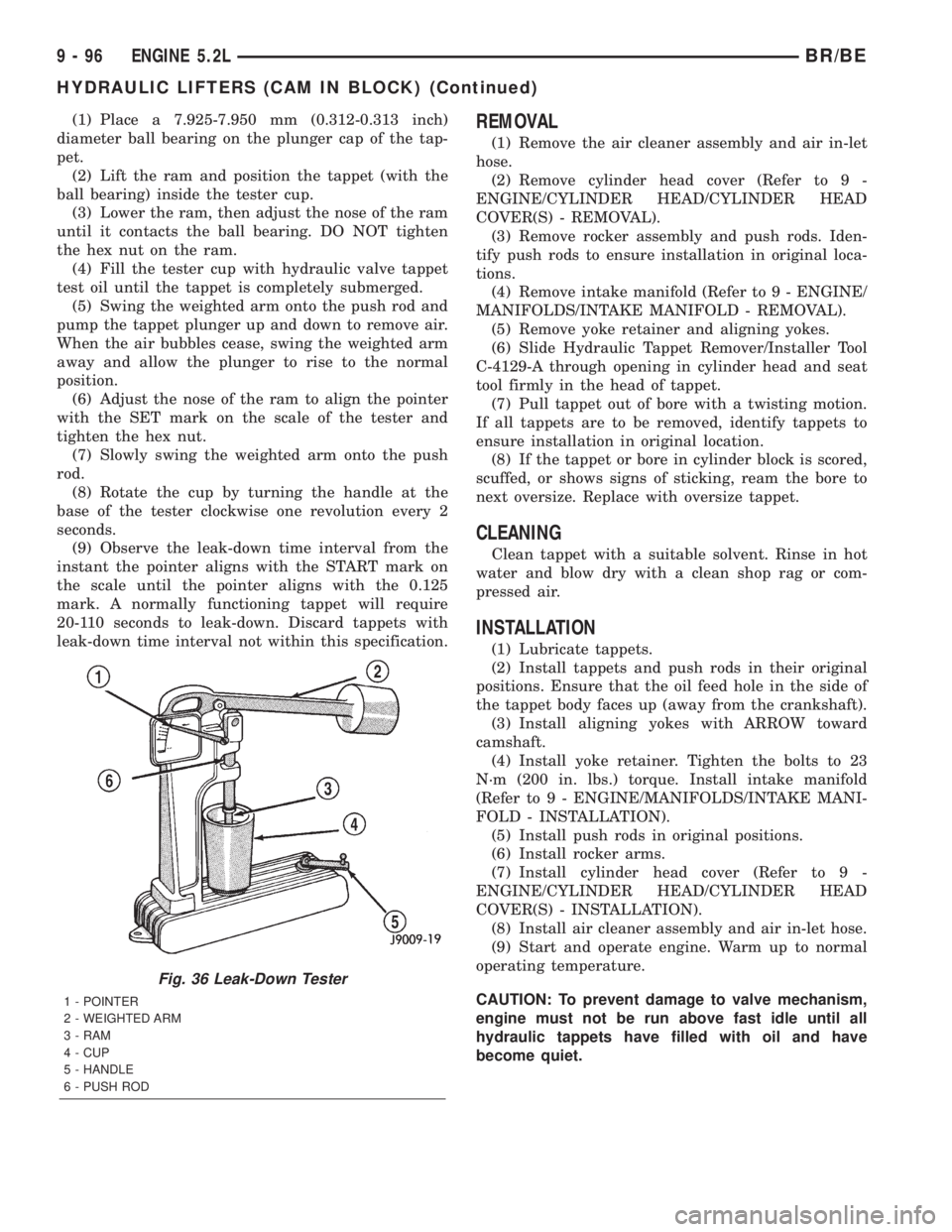
(1) Place a 7.925-7.950 mm (0.312-0.313 inch)
diameter ball bearing on the plunger cap of the tap-
pet.
(2) Lift the ram and position the tappet (with the
ball bearing) inside the tester cup.
(3) Lower the ram, then adjust the nose of the ram
until it contacts the ball bearing. DO NOT tighten
the hex nut on the ram.
(4) Fill the tester cup with hydraulic valve tappet
test oil until the tappet is completely submerged.
(5) Swing the weighted arm onto the push rod and
pump the tappet plunger up and down to remove air.
When the air bubbles cease, swing the weighted arm
away and allow the plunger to rise to the normal
position.
(6) Adjust the nose of the ram to align the pointer
with the SET mark on the scale of the tester and
tighten the hex nut.
(7) Slowly swing the weighted arm onto the push
rod.
(8) Rotate the cup by turning the handle at the
base of the tester clockwise one revolution every 2
seconds.
(9) Observe the leak-down time interval from the
instant the pointer aligns with the START mark on
the scale until the pointer aligns with the 0.125
mark. A normally functioning tappet will require
20-110 seconds to leak-down. Discard tappets with
leak-down time interval not within this specification.REMOVAL
(1) Remove the air cleaner assembly and air in-let
hose.
(2) Remove cylinder head cover (Refer to 9 -
ENGINE/CYLINDER HEAD/CYLINDER HEAD
COVER(S) - REMOVAL).
(3) Remove rocker assembly and push rods. Iden-
tify push rods to ensure installation in original loca-
tions.
(4) Remove intake manifold (Refer to 9 - ENGINE/
MANIFOLDS/INTAKE MANIFOLD - REMOVAL).
(5) Remove yoke retainer and aligning yokes.
(6) Slide Hydraulic Tappet Remover/Installer Tool
C-4129-A through opening in cylinder head and seat
tool firmly in the head of tappet.
(7) Pull tappet out of bore with a twisting motion.
If all tappets are to be removed, identify tappets to
ensure installation in original location.
(8) If the tappet or bore in cylinder block is scored,
scuffed, or shows signs of sticking, ream the bore to
next oversize. Replace with oversize tappet.
CLEANING
Clean tappet with a suitable solvent. Rinse in hot
water and blow dry with a clean shop rag or com-
pressed air.
INSTALLATION
(1) Lubricate tappets.
(2) Install tappets and push rods in their original
positions. Ensure that the oil feed hole in the side of
the tappet body faces up (away from the crankshaft).
(3) Install aligning yokes with ARROW toward
camshaft.
(4) Install yoke retainer. Tighten the bolts to 23
N´m (200 in. lbs.) torque. Install intake manifold
(Refer to 9 - ENGINE/MANIFOLDS/INTAKE MANI-
FOLD - INSTALLATION).
(5) Install push rods in original positions.
(6) Install rocker arms.
(7) Install cylinder head cover (Refer to 9 -
ENGINE/CYLINDER HEAD/CYLINDER HEAD
COVER(S) - INSTALLATION).
(8) Install air cleaner assembly and air in-let hose.
(9) Start and operate engine. Warm up to normal
operating temperature.
CAUTION: To prevent damage to valve mechanism,
engine must not be run above fast idle until all
hydraulic tappets have filled with oil and have
become quiet.
Fig. 36 Leak-Down Tester
1 - POINTER
2 - WEIGHTED ARM
3 - RAM
4 - CUP
5 - HANDLE
6 - PUSH ROD
9 - 96 ENGINE 5.2LBR/BE
HYDRAULIC LIFTERS (CAM IN BLOCK) (Continued)
Page 1246 of 2889
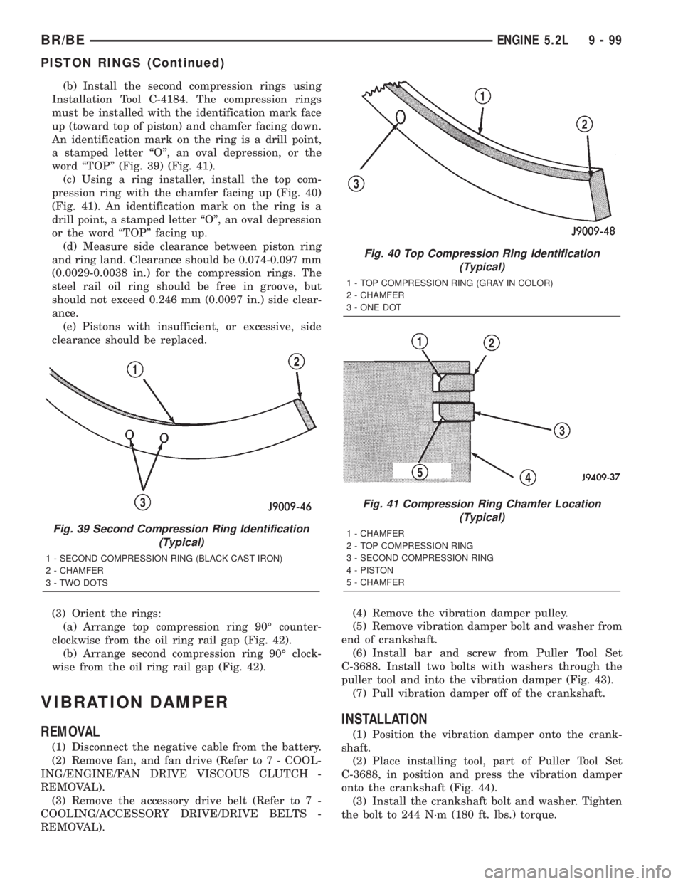
(b) Install the second compression rings using
Installation Tool C-4184. The compression rings
must be installed with the identification mark face
up (toward top of piston) and chamfer facing down.
An identification mark on the ring is a drill point,
a stamped letter ªOº, an oval depression, or the
word ªTOPº (Fig. 39) (Fig. 41).
(c) Using a ring installer, install the top com-
pression ring with the chamfer facing up (Fig. 40)
(Fig. 41). An identification mark on the ring is a
drill point, a stamped letter ªOº, an oval depression
or the word ªTOPº facing up.
(d) Measure side clearance between piston ring
and ring land. Clearance should be 0.074-0.097 mm
(0.0029-0.0038 in.) for the compression rings. The
steel rail oil ring should be free in groove, but
should not exceed 0.246 mm (0.0097 in.) side clear-
ance.
(e) Pistons with insufficient, or excessive, side
clearance should be replaced.
(3) Orient the rings:
(a) Arrange top compression ring 90É counter-
clockwise from the oil ring rail gap (Fig. 42).
(b) Arrange second compression ring 90É clock-
wise from the oil ring rail gap (Fig. 42).
VIBRATION DAMPER
REMOVAL
(1) Disconnect the negative cable from the battery.
(2) Remove fan, and fan drive (Refer to 7 - COOL-
ING/ENGINE/FAN DRIVE VISCOUS CLUTCH -
REMOVAL).
(3) Remove the accessory drive belt (Refer to 7 -
COOLING/ACCESSORY DRIVE/DRIVE BELTS -
REMOVAL).(4) Remove the vibration damper pulley.
(5) Remove vibration damper bolt and washer from
end of crankshaft.
(6) Install bar and screw from Puller Tool Set
C-3688. Install two bolts with washers through the
puller tool and into the vibration damper (Fig. 43).
(7) Pull vibration damper off of the crankshaft.
INSTALLATION
(1) Position the vibration damper onto the crank-
shaft.
(2) Place installing tool, part of Puller Tool Set
C-3688, in position and press the vibration damper
onto the crankshaft (Fig. 44).
(3) Install the crankshaft bolt and washer. Tighten
the bolt to 244 N´m (180 ft. lbs.) torque.
Fig. 39 Second Compression Ring Identification
(Typical)
1 - SECOND COMPRESSION RING (BLACK CAST IRON)
2 - CHAMFER
3 - TWO DOTS
Fig. 40 Top Compression Ring Identification
(Typical)
1 - TOP COMPRESSION RING (GRAY IN COLOR)
2 - CHAMFER
3 - ONE DOT
Fig. 41 Compression Ring Chamfer Location
(Typical)
1 - CHAMFER
2 - TOP COMPRESSION RING
3 - SECOND COMPRESSION RING
4 - PISTON
5 - CHAMFER
BR/BEENGINE 5.2L 9 - 99
PISTON RINGS (Continued)
Page 1299 of 2889
NOTE: Worn valve guides or cocked springs are
sometimes mistaken for noisy tappets. If such is the
case, noise may be dampened by applying side thrust
on the valve spring. If noise is not appreciably
reduced, it can be assumed the noise is in the tappet.
Inspect the rocker arm push rod sockets and push rod
ends for wear.
(3)Valve tappet noise ranges from light noise to a
heavy click. A light noise is usually caused by excessive
leak-down around the unit plunger, or by the plunger
partially sticking in the tappet body cylinder. The tap-
pet should be replaced. A heavy click is caused by a tap-
pet check valve not seating, or by foreign particles
wedged between the plunger and the tappet body. This
will cause the plunger to stick in the down position.
This heavy click will be accompanied by excessive clear-
ance between the valve stem and rocker arm as valve
closes. In either case, tappet assembly should be
removed for inspection and cleaning.
(4) The valve train generates a noise very much
like a light tappet noise during normal operation.
Care must be taken to ensure that tappets are mak-
ing the noise. If more than one tappet seems to be
noisy, it's probably not the tappets.
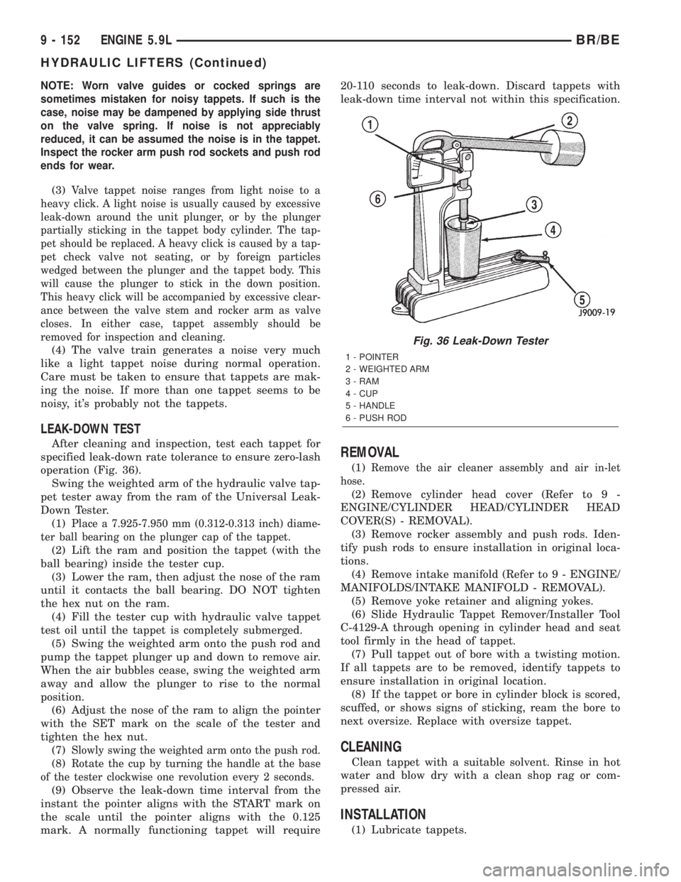
LEAK-DOWN TEST
After cleaning and inspection, test each tappet for
specified leak-down rate tolerance to ensure zero-lash
operation (Fig. 36).
Swing the weighted arm of the hydraulic valve tap-
pet tester away from the ram of the Universal Leak-
Down Tester.
(1)
Place a 7.925-7.950 mm (0.312-0.313 inch) diame-
ter ball bearing on the plunger cap of the tappet.
(2) Lift the ram and position the tappet (with the
ball bearing) inside the tester cup.
(3) Lower the ram, then adjust the nose of the ram
until it contacts the ball bearing. DO NOT tighten
the hex nut on the ram.
(4) Fill the tester cup with hydraulic valve tappet
test oil until the tappet is completely submerged.
(5) Swing the weighted arm onto the push rod and
pump the tappet plunger up and down to remove air.
When the air bubbles cease, swing the weighted arm
away and allow the plunger to rise to the normal
position.
(6) Adjust the nose of the ram to align the pointer
with the SET mark on the scale of the tester and
tighten the hex nut.
(7)
Slowly swing the weighted arm onto the push rod.
(8)Rotate the cup by turning the handle at the base
of the tester clockwise one revolution every 2 seconds.
(9) Observe the leak-down time interval from the
instant the pointer aligns with the START mark on
the scale until the pointer aligns with the 0.125
mark. A normally functioning tappet will require20-110 seconds to leak-down. Discard tappets with
leak-down time interval not within this specification.
REMOVAL
(1)Remove the air cleaner assembly and air in-let
hose.
(2) Remove cylinder head cover (Refer to 9 -
ENGINE/CYLINDER HEAD/CYLINDER HEAD
COVER(S) - REMOVAL).
(3) Remove rocker assembly and push rods. Iden-
tify push rods to ensure installation in original loca-
tions.
(4) Remove intake manifold (Refer to 9 - ENGINE/
MANIFOLDS/INTAKE MANIFOLD - REMOVAL).
(5) Remove yoke retainer and aligning yokes.
(6) Slide Hydraulic Tappet Remover/Installer Tool
C-4129-A through opening in cylinder head and seat
tool firmly in the head of tappet.
(7) Pull tappet out of bore with a twisting motion.
If all tappets are to be removed, identify tappets to
ensure installation in original location.
(8) If the tappet or bore in cylinder block is scored,
scuffed, or shows signs of sticking, ream the bore to
next oversize. Replace with oversize tappet.
CLEANING
Clean tappet with a suitable solvent. Rinse in hot
water and blow dry with a clean shop rag or com-
pressed air.
INSTALLATION
(1) Lubricate tappets.
Fig. 36 Leak-Down Tester
1 - POINTER
2 - WEIGHTED ARM
3 - RAM
4 - CUP
5 - HANDLE
6 - PUSH ROD
9 - 152 ENGINE 5.9LBR/BE
HYDRAULIC LIFTERS (Continued)