2001 DODGE RAM set clock
[x] Cancel search: set clockPage 379 of 2889
(4) Install fan blade/viscous fan drive assembly to
water pump shaft (Fig. 6).
(5) Except 8.0L V-10 Engine: Install coolant
reserve/overflow tank to fan shroud. Snaps into posi-
tion.
(6) Install throttle cable to fan shroud.
(7) Connect negative battery cable.
NOTE: Viscous Fan Drive Fluid Pump Out Require-
ment: After installing a new viscous fan drive, bring
the engine speed up to approximately 2000 rpm and
hold for approximately two minutes. This will
ensure proper fluid distribution within the drive.
RADIATOR FAN - 5.9L DIESEL
REMOVAL
CAUTION: If the viscous fan drive is replaced
because of mechanical damage, the cooling fan
blades should also be inspected. Inspect for fatigue
cracks, loose blades, or loose rivets that could
have resulted from excessive vibration. Replace fan
blade assembly if any of these conditions are
found. Also inspect water pump bearing and shaft
assembly for any related damage due to a viscous
fan drive malfunction.
(1) Disconnect the battery negative cables.
(2) Remove the fan shroud mounting bolts. Posi-
tion fan shroud towards engine.
CAUTION: Do not remove the fan pulley bolts. This
pulley is under spring tension.
(3) The thermal viscous fan drive/fan blade assem-
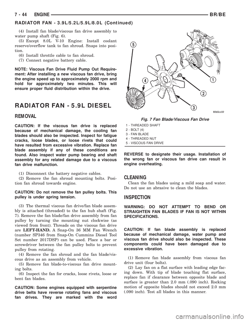
bly is attached (threaded) to the fan hub shaft (Fig.
7). Remove the fan blade/fan drive assembly from fan
pulley by turning the mounting nut clockwise (as
viewed from front). Threads on the viscous fan drive
areLEFT-HAND.A Snap-On 36 MM Fan Wrench
(number SP346 from Snap-On Cummins Diesel Tool
Set number 2017DSP) can be used. Place a bar or
screwdriver between the fan pulley bolts to prevent
pulley from rotating.
(4) Remove the fan shroud and the fan blade/vis-
cous drive as an assembly from vehicle.
(5) Remove fan blade-to-viscous fan drive mount-
ing bolts.
(6) Inspect the fan for cracks, loose rivets, loose or
bent fan blades.
CAUTION: Some engines equipped with serpentine
drive belts have reverse rotating fans and viscous
fan drives. They are marked with the wordREVERSE to designate their usage. Installation of
the wrong fan or viscous fan drive can result in
engine overheating.
CLEANING
Clean the fan blades using a mild soap and water.
Do not use an abrasive to clean the blades.
INSPECTION
WARNING: DO NOT ATTEMPT TO BEND OR
STRAIGHTEN FAN BLADES IF FAN IS NOT WITHIN
SPECIFICATIONS.
CAUTION: If fan blade assembly is replaced
because of mechanical damage, water pump and
viscous fan drive should also be inspected. These
components could have been damaged due to
excessive vibration.
(1) Remove fan blade assembly from viscous fan
drive unit (four bolts).
(2) Lay fan on a flat surface with leading edge fac-
ing down. With tip of blade touching flat surface,
replace fan if clearance between opposite blade and
surface is greater than 2.0 mm (.090 inch). Rocking
motion of opposite blades should not exceed 2.0 mm
(.090 inch). Test all blades in this manner.
Fig. 7 Fan Blade/Viscous Fan Drive
1 - THREADED SHAFT
2 - BOLT (4)
3 - FAN BLADE
4 - THREADED NUT
5 - VISCOUS FAN DRIVE
7 - 44 ENGINEBR/BE
RADIATOR FAN - 3.9L/5.2L/5.9L/8.0L (Continued)
Page 403 of 2889
(4) Disconnect the coolant reserve/overflow tank-
to-radiator hose at the tank.
(5) Remove the four fan shroud mounting bolts at
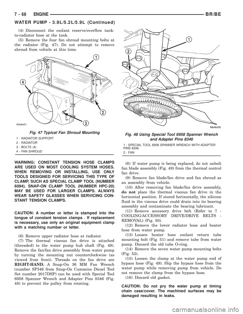
the radiator (Fig. 47). Do not attempt to remove
shroud from vehicle at this time.
WARNING: CONSTANT TENSION HOSE CLAMPS
ARE USED ON MOST COOLING SYSTEM HOSES.
WHEN REMOVING OR INSTALLING, USE ONLY
TOOLS DESIGNED FOR SERVICING THIS TYPE OF
CLAMP, SUCH AS SPECIAL CLAMP TOOL (NUMBER
6094). SNAP-ON CLAMP TOOL (NUMBER HPC-20)
MAY BE USED FOR LARGER CLAMPS. ALWAYS
WEAR SAFETY GLASSES WHEN SERVICING CON-
STANT TENSION CLAMPS.
CAUTION: A number or letter is stamped into the
tongue of constant tension clamps . If replacement
is necessary, use only an original equipment clamp
with a matching number or letter.
(6) Remove upper radiator hose at radiator.
(7) The thermal viscous fan drive is attached
(threaded) to the water pump hub shaft (Fig. 49).
Remove the fan/fan drive assembly from water pump
by turning the mounting nut counterclockwise (as
viewed from front). Threads on the fan drive are
RIGHT-HAND.A Snap-On 36 MM Fan Wrench
(number SP346 from Snap-On Cummins Diesel Tool
Set number 2017DSP) can be used with Special Tool
6958 Spanner Wrench and Adapter Pins 8346 (Fig.
48) to prevent the pulley from rotating.(8) If water pump is being replaced, do not unbolt
fan blade assembly (Fig. 49) from the thermal control
fan drive.
(9) Remove fan blade/fan drive and fan shroud as
an assembly from vehicle.
(10) After removing fan blade/fan drive assembly,
do notplace the thermal viscous fan drive in the
horizontal position. If stored horizontally, the silicone
fluid in the viscous drive could drain into its bearing
assembly and contaminate the bearing lubricant.
(11) Remove accessory drive belt (Refer to 7 -
COOLING/ACCESSORY DRIVE/DRIVE BELTS -
REMOVAL) (Fig. 50).
(12) Remove the lower radiator hose and heater
hose from water pump.
(13) Loosen heater hose coolant return tube
mounting bolt (Fig. 51) and remove tube from water
pump. Discard the old tube O-ring.
(14) Remove the seven water pump mounting bolts
(Fig. 52).
(15) Loosen the clamp at the water pump end of
bypass hose (Fig. 49). Slip the bypass hose from the
water pump while removing pump from vehicle. Do
not remove the clamp from the bypass hose.
(16) Discard old gasket.
CAUTION: Do not pry the water pump at timing
chain case/cover. The machined surfaces may be
damaged resulting in leaks.
Fig. 47 Typical Fan Shroud Mounting
1 - RADIATOR SUPPORT
2 - RADIATOR
3 - BOLTS (4)
4 - FAN SHROUDFig. 48 Using Special Tool 6958 Spanner Wrench
and Adapter Pins 8346
1 - SPECIAL TOOL 6958 SPANNER WRENCH WITH ADAPTER
PINS 8346
2-FAN
7 - 68 ENGINEBR/BE
WATER PUMP - 3.9L/5.2L/5.9L (Continued)
Page 406 of 2889
CAUTION: A number or letter is stamped into the
tongue of constant tension clamps. If replacement
is necessary, use only an original equipment clamp
with a matching number or letter.
(5) Remove radiator upper hose at radiator.
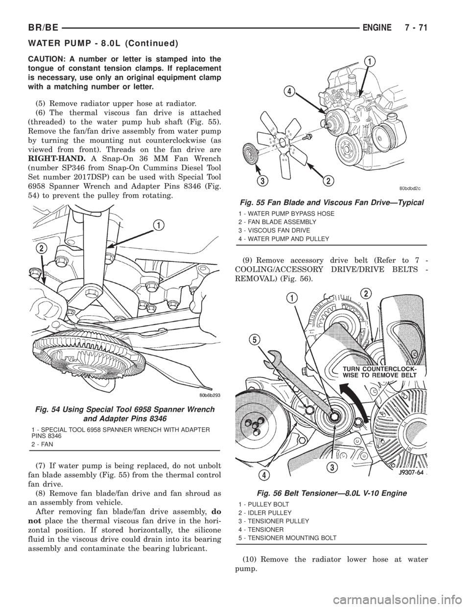
(6) The thermal viscous fan drive is attached
(threaded) to the water pump hub shaft (Fig. 55).
Remove the fan/fan drive assembly from water pump
by turning the mounting nut counterclockwise (as
viewed from front). Threads on the fan drive are
RIGHT-HAND.A Snap-On 36 MM Fan Wrench
(number SP346 from Snap-On Cummins Diesel Tool
Set number 2017DSP) can be used with Special Tool
6958 Spanner Wrench and Adapter Pins 8346 (Fig.
54) to prevent the pulley from rotating.
(7) If water pump is being replaced, do not unbolt
fan blade assembly (Fig. 55) from the thermal control
fan drive.
(8) Remove fan blade/fan drive and fan shroud as
an assembly from vehicle.
After removing fan blade/fan drive assembly,do
notplace the thermal viscous fan drive in the hori-
zontal position. If stored horizontally, the silicone
fluid in the viscous drive could drain into its bearing
assembly and contaminate the bearing lubricant.(9) Remove accessory drive belt (Refer to 7 -
COOLING/ACCESSORY DRIVE/DRIVE BELTS -
REMOVAL) (Fig. 56).
(10) Remove the radiator lower hose at water
pump.
Fig. 54 Using Special Tool 6958 Spanner Wrench
and Adapter Pins 8346
1 - SPECIAL TOOL 6958 SPANNER WRENCH WITH ADAPTER
PINS 8346
2-FAN
Fig. 55 Fan Blade and Viscous Fan DriveÐTypical
1 - WATER PUMP BYPASS HOSE
2 - FAN BLADE ASSEMBLY
3 - VISCOUS FAN DRIVE
4 - WATER PUMP AND PULLEY
Fig. 56 Belt TensionerÐ8.0L V-10 Engine
1 - PULLEY BOLT
2 - IDLER PULLEY
3 - TENSIONER PULLEY
4 - TENSIONER
5 - TENSIONER MOUNTING BOLT
BR/BEENGINE 7 - 71
WATER PUMP - 8.0L (Continued)
Page 424 of 2889
AUDIO
TABLE OF CONTENTS
page page
AUDIO
DESCRIPTION............................1
OPERATION.............................2
DIAGNOSIS AND TESTING..................2
AUDIO................................2
SPECIAL TOOLS..........................4
ANTENNA BODY & CABLE
DESCRIPTION............................4
OPERATION.............................4
DIAGNOSIS AND TESTING..................5
ANTENNA.............................5
REMOVAL...............................6
INSTALLATION............................7
RADIO CHOKE RELAY
DESCRIPTION............................8
OPERATION.............................8
DIAGNOSIS AND TESTING..................8
RADIO CHOKE RELAY....................8
REMOVAL...............................9
INSTALLATION............................9
INSTRUMENT PANEL ANTENNA CABLE
REMOVAL...............................9
INSTALLATION...........................10
RADIO
DESCRIPTION...........................10
OPERATION.............................10
DIAGNOSIS AND TESTING.................10
RADIO...............................10
REMOVAL..............................11
INSTALLATION...........................12
RADIO NOISE SUPPRESSION COMPONENTS
DESCRIPTION...........................12
DIAGNOSIS AND TESTING.................12
RADIO NOISE SUPPRESSION
COMPONENTS.........................12ENGINE-TO-BODY GROUND STRAP
REMOVAL..............................13
INSTALLATION...........................13
CAB-TO- BED GROUND STRAP
REMOVAL..............................14
INSTALLATION...........................14
HEATER CORE GROUND STRAP
REMOVAL..............................14
INSTALLATION...........................15
REMOTE SWITCHES
DESCRIPTION...........................15
OPERATION.............................15
DIAGNOSIS AND TESTING.................16
REMOTE SWITCHES....................16
REMOVAL..............................16
INSTALLATION...........................17
SPEAKER
DESCRIPTION...........................17
OPERATION.............................17
DIAGNOSIS AND TESTING.................18
SPEAKER............................18
A-PILLAR TWEETER SPEAKER
REMOVAL..............................19
INSTALLATION...........................19
FRONT DOOR SPEAKER
REMOVAL..............................20
INSTALLATION...........................20
REAR CAB SIDE PANEL SPEAKER
REMOVAL..............................20
INSTALLATION...........................21
REAR DOOR SPEAKER
REMOVAL..............................21
INSTALLATION...........................21
AUDIO
DESCRIPTION
An audio system is standard factory-installed equip-
ment on this model, unless the vehicle is ordered with
an available radio delete option. The standard equip-
ment audio system includes an AM/FM/cassette (RAS
sales code) receiver, and speakers in four locations. Sev-
eral combinations of radio receivers and speaker systems
are offered as optional equipment on this model. The
audio system uses an ignition switched source of battery
current so that the system will only operate when theignition switch is in the On or Accessory positions. The
audio system includes the following components:
²Antenna
²Clockspring (with remote radio switches only)
²Filter, choke and speaker relay (with premium
speaker system only)
²High-line or premium Central Timer Module
(CTM) (with remote radio switches)
²Radio noise suppression components
²Radio receiver
²Remote radio switches (optional with RAZ radio
receiver only)
²Speakers
BR/BEAUDIO 8A - 1
Page 425 of 2889
Refer to Electrical, Restraints for more information
on the clockspring. Refer to Electrical, Body Control/
Central Control Module for more information on the
Central Timer Module. Refer to the appropriate wir-
ing information. The wiring information includes wir-
ing diagrams, proper wire and connector repair
procedures, details of wire harness routing and
retention, connector pin-out information and location
views for the various wire harness connectors, splices
and grounds. Following are general descriptions of
the remaining major components in the standard and
optional factory-installed audio systems.
OPERATION
See the owner's manual in the vehicle glove box for
more information on the features, use and operation
of each of the available audio systems.
CENTRAL TIMER MODULE
The high-line or premium Central Timer Module
(CTM) can also control some features of the audio
system when the vehicle is equipped with the
optional RAZ radio receiver and remote radio
switches. A high-line CTM is used on high-line ver-
sions of this vehicle. A premium CTM is used on
vehicles equipped with the optional heated seats. The
CTM combines the functions of a chime/buzzer mod-
ule, an intermittent wipe module, an illuminated
entry module, a remote keyless entry module, and a
vehicle theft security system module in a single unit.
The high-line or premium CTM also controls and
integrates many of the additional electronic functions
and features included on models with this option.The RAZ radio receiver with a remote radio switch
option is one of the features that the CTM controls.
The CTM is programmed to send switch status mes-
sages over the Chrysler Collision Detection (CCD)
data bus to control the volume, seek, and pre-set sta-
tion advance functions of the RAZ radio receiver. The
CTM monitors the status of the remote radio
switches located on the steering wheel through a
hard wired circuit. The CTM then sends the proper
switch status messages to the radio receiver. The
electronic circuitry within the radio receiver responds
to the switch status messages it receives by adjusting
the radio settings as requested.
Refer to Electrical, Body Control/Central Timer
Module for more information on the high-line CTM.
Refer to Remote Radio Switch in Description and
Operation for more information on this component.
In addition, radio receivers connected to the CCD
data bus have several audio system functions that
can be diagnosed using a DRBIIItscan tool. Refer to
the proper Diagnostic Procedures manual for more
information on DRBIIIttesting of the audio systems.
DIAGNOSIS AND TESTING - AUDIO
WARNING: ON VEHICLES EQUIPPED WITH AIR-
BAGS, REFER TO ELECTRICAL, RESTRAINTS
BEFORE ATTEMPTING ANY STEERING WHEEL,
STEERING COLUMN, OR INSTRUMENT PANEL
COMPONENT DIAGNOSIS OR SERVICE. FAILURE
TO TAKE THE PROPER PRECAUTIONS COULD
RESULT IN ACCIDENTAL AIRBAG DEPLOYMENT
AND POSSIBLE PERSONAL INJURY.
8A - 2 AUDIOBR/BE
AUDIO (Continued)
Page 426 of 2889
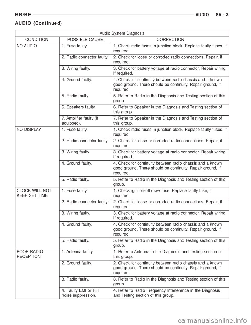
Audio System Diagnosis
CONDITION POSSIBLE CAUSE CORRECTION
NO AUDIO 1. Fuse faulty. 1. Check radio fuses in junction block. Replace faulty fuses, if
required.
2. Radio connector faulty. 2. Check for loose or corroded radio connections. Repair, if
required.
3. Wiring faulty. 3. Check for battery voltage at radio connector. Repair wiring,
if required.
4. Ground faulty. 4. Check for continuity between radio chassis and a known
good ground. There should be continuity. Repair ground, if
required.
5. Radio faulty. 5. Refer to Radio in the Diagnosis and Testing section of this
group.
6. Speakers faulty. 6. Refer to Speaker in the Diagnosis and Testing section of
this group.
7. Amplifier faulty (if
equipped).7. Refer to Speaker in the Diagnosis and Testing section of
this group.
NO DISPLAY 1. Fuse faulty. 1. Check radio fuses in junction block. Replace faulty fuses, if
required.
2. Radio connector faulty. 2. Check for loose or corroded radio connections. Repair, if
required.
3. Wiring faulty. 3. Check for battery voltage at radio connector. Repair wiring,
if required.
4. Ground faulty. 4. Check for continuity between radio chassis and a known
good ground. There should be continuity. Repair ground, if
required.
5. Radio faulty. 5. Refer to Radio in the Diagnosis and Testing section of this
group.
CLOCK WILL NOT
KEEP SET TIME1. Fuse faulty. 1. Check ignition-off draw fuse. Replace faulty fuse, if
required.
2. Radio connector faulty. 2. Check for loose or corroded radio connections. Repair, if
required.
3. Wiring faulty. 3. Check for battery voltage at radio connector. Repair wiring,
if required.
4. Ground faulty. 4. Check for continuity between radio chassis and a known
good ground. There should be continuity. Repair ground, if
required.
5. Radio faulty. 5. Refer to Radio in the Diagnosis and Testing section of this
group.
POOR RADIO
RECEPTION1. Antenna faulty. 1. Refer to Antenna in the Diagnosis and Testing section of
this group.
2. Ground faulty. 2. Check for continuity between radio chassis and a known
good ground. There should be continuity. Repair ground, if
required.
3. Radio faulty. 3. Refer to Radio in the Diagnosis and Testing section of this
group.
4. Faulty EMI or RFI
noise suppression.4. Refer to Radio Frequency Interference in the Diagnosis
and Testing section of this group.
BR/BEAUDIO 8A - 3
AUDIO (Continued)
Page 433 of 2889
(7) Remove the radio receiver from the instrument
panel. Refer to Audio, Radio for the procedures.
(8) Pull the antenna cable out through the radio
receiver opening in the instrument panel.
(9) Untie the cord or twine from the instrument
panel antenna cable connector, leaving the cord or
twine in place of the cable in the instrument panel.
(10) Remove the antenna cable from the instru-
ment panel.
INSTALLATION
(1) Tie the end of the cord or twine that was used
during instrument panel antenna cable removal
securely to the connector on the end of the antenna
cable being installed into the instrument panel. This
cord will be used to pull or ªfishº the cable back into
position.
(2) Using the cord or twine, pull the antenna cable
through the radio receiver opening from under the
instrument panel.
(3) Install the radio receiver onto the instrument
panel. Refer to Audio, Radio for the procedures.
(4) Reach through the glove box opening to engage
the antenna cable with the retainer clips on the back
of the instrument panel.
(5) Install the glove box onto the instrument panel.
Refer to Body, Instrument Panel for the procedures.
(6) Untie the cord or twine from the instrument
panel antenna cable connector.
(7) Reach under the passenger side of the instru-
ment panel near the right cowl side inner panel to
reconnect the two halves of the radio antenna coaxial
cable connector. Wrap the connection with a piece of
foam tape.
(8) Engage the coaxial cable connector with the
retainer clip located on the bottom of the heater-A/C
housing.
(9) Reconnect the battery negative cable.
RADIO
DESCRIPTION
Available factory-installed radio receivers for this
model include an AM/FM/cassette (RAS sales code),
an AM/FM/cassette/5-band graphic equalizer with CD
changer control feature (RBN sales code), an AM/FM/
CD/3-band graphic equalizer (RBR sales code), or an
AM/FM/CD/cassette/3-band graphic equalizer (RAZ
sales code). The factory-installed RAZ sales code
radio receivers can also communicate on the Chrysler
Collision Detection (CCD) data bus network through
a separate two-way wire harness connector. All facto-
ry-installed receivers are stereo Electronically Tuned
Radios (ETR) and include an electronic digital clock
function.These radio receivers can only be serviced by an
authorized radio repair station. See the latest War-
ranty Policies and Procedures manual for a current
listing of authorized radio repair stations.
All vehicles are equipped with an Ignition-Off
Draw (IOD) fuse that is removed when the vehicle is
shipped from the factory. This fuse feeds various
accessories that require battery current when the
ignition switch is in the Off position, including the
clock. The IOD fuse is removed to prevent battery
discharge during vehicle storage.
When removing or installing the IOD fuse, it is
important that the ignition switch be in the Off posi-
tion. Failure to place the ignition switch in the Off
position can cause the radio display to become scram-
bled when the IOD fuse is removed and replaced.
Removing and replacing the IOD fuse again, with the
ignition switch in the Off position, will correct the
scrambled display condition.
The IOD fuse should be checked if the radio or
clock displays are inoperative. The IOD fuse is
located in the junction block. Refer to the fuse layout
label on the back of the instrument panel fuse access
panel for IOD fuse identification and location.
OPERATION
The radio receiver operates on fused battery cur-
rent that is available only when the ignition switch is
in the On or Accessory positions. The electronic digi-
tal clock function of the radio operates on fused bat-
tery current supplied through the IOD fuse,
regardless of the ignition switch position.
For more information on the features, setting pro-
cedures, and control functions for each of the avail-
able factory-installed radio receivers, see the owner's
manual in the vehicle glove box. For complete circuit
diagrams, refer to the appropriate wiring informa-
tion. The wiring information includes wiring dia-
grams, proper wire and connector repair procedures,
details of wire harness routing and retention, connec-
tor pin-out information and location views for the
various wire harness connectors, splices and grounds.
DIAGNOSIS AND TESTING
DIAGNOSIS AND TESTING - RADIO
If the vehicle is equipped with the optional remote
radio switches located on the steering wheel and the
problem being diagnosed is related to one of the
symptoms listed below, be certain to check the
remote radio switches and circuits. Refer to Audio,
Remote Radio Switch prior to attempting radio diag-
nosis or repair.
²Stations changing with no remote radio switch
input
8A - 10 AUDIOBR/BE
INSTRUMENT PANEL ANTENNA CABLE (Continued)
Page 438 of 2889
(6) Remove the heater core ground strap from the
top of the heater-A/C housing.
INSTALLATION
(1) Position the heater core ground strap and the
heater core tube retaining strap to the top of the
heater-A/C housing.
(2) Install and tighten the screw that secures the
heater core ground strap eyelet and the heater core
tube retaining strap to the top of the heater-A/C
housing. Tighten the screw to 2.2 N´m (20 in. lbs.).
(3) Position the heater core ground strap eyelet
over the stud on the dash panel.
(4) Install and tighten the nut that secures the
heater core ground strap eyelet to the stud on the
dash panel. Tighten the nut to 3.9 N´m (35 in. lbs.).
(5) Install the glove box onto the instrument panel.
Refer to Body, Instrument Panel for the procedures.
(6) Reconnect the battery negative cable.
REMOTE SWITCHES
DESCRIPTION
A remote radio switch option is available on models
equipped with the AM/FM/CD/cassette/3-band
graphic equalizer (RAZ sales code) radio receiver and
the high-line Central Timer Module (CTM). Refer to
Electrical, Body Control/Central Timer Module for
more information on this component.
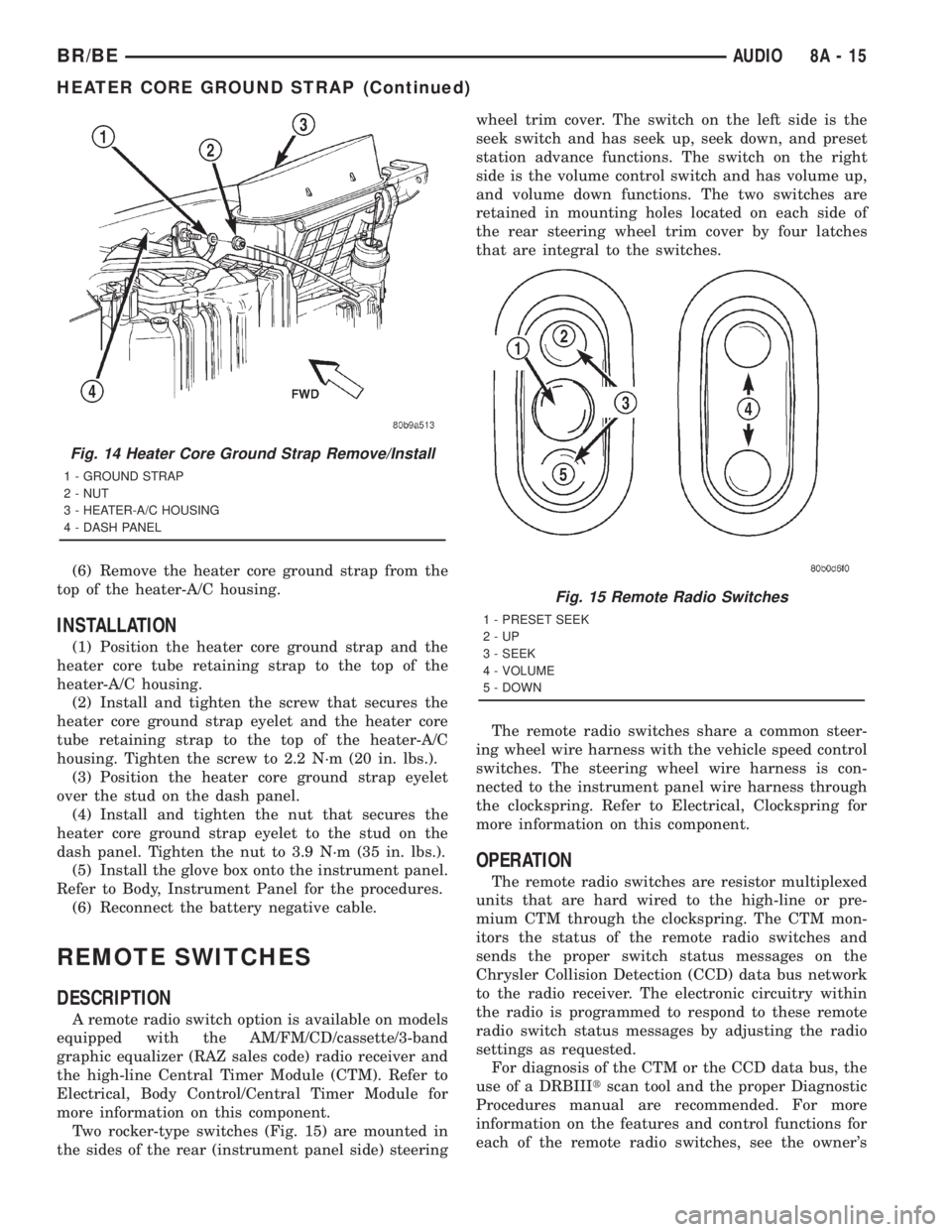
Two rocker-type switches (Fig. 15) are mounted in
the sides of the rear (instrument panel side) steeringwheel trim cover. The switch on the left side is the
seek switch and has seek up, seek down, and preset
station advance functions. The switch on the right
side is the volume control switch and has volume up,
and volume down functions. The two switches are
retained in mounting holes located on each side of
the rear steering wheel trim cover by four latches
that are integral to the switches.
The remote radio switches share a common steer-
ing wheel wire harness with the vehicle speed control
switches. The steering wheel wire harness is con-
nected to the instrument panel wire harness through
the clockspring. Refer to Electrical, Clockspring for
more information on this component.
OPERATION
The remote radio switches are resistor multiplexed
units that are hard wired to the high-line or pre-
mium CTM through the clockspring. The CTM mon-
itors the status of the remote radio switches and
sends the proper switch status messages on the
Chrysler Collision Detection (CCD) data bus network
to the radio receiver. The electronic circuitry within
the radio is programmed to respond to these remote
radio switch status messages by adjusting the radio
settings as requested.
For diagnosis of the CTM or the CCD data bus, the
use of a DRBIIItscan tool and the proper Diagnostic
Procedures manual are recommended. For more
information on the features and control functions for
each of the remote radio switches, see the owner's
Fig. 14 Heater Core Ground Strap Remove/Install
1 - GROUND STRAP
2 - NUT
3 - HEATER-A/C HOUSING
4 - DASH PANEL
Fig. 15 Remote Radio Switches
1 - PRESET SEEK
2-UP
3 - SEEK
4 - VOLUME
5 - DOWN
BR/BEAUDIO 8A - 15
HEATER CORE GROUND STRAP (Continued)