2001 DODGE RAM wheel torque
[x] Cancel search: wheel torquePage 107 of 2889
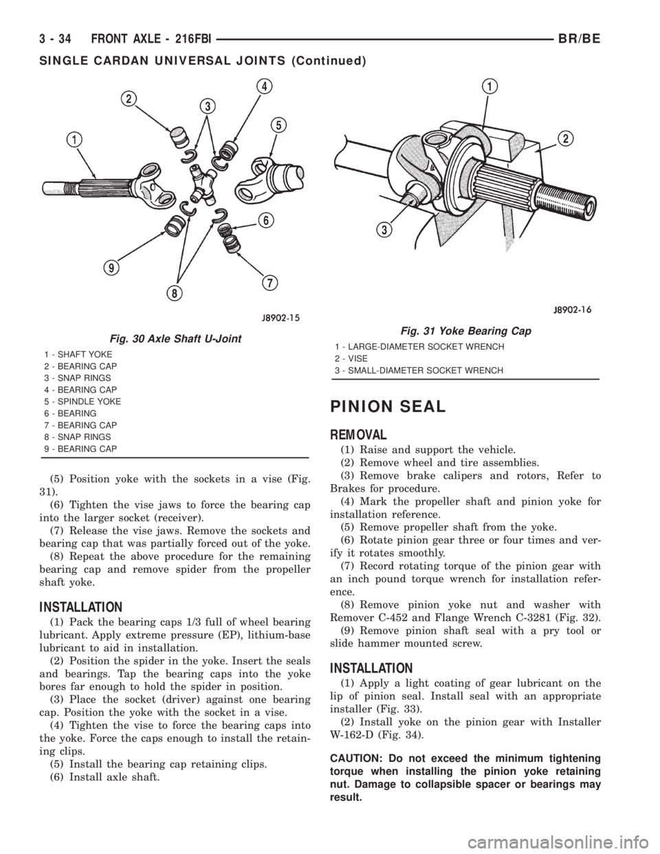
(5) Position yoke with the sockets in a vise (Fig.
31).
(6) Tighten the vise jaws to force the bearing cap
into the larger socket (receiver).
(7) Release the vise jaws. Remove the sockets and
bearing cap that was partially forced out of the yoke.
(8) Repeat the above procedure for the remaining
bearing cap and remove spider from the propeller
shaft yoke.
INSTALLATION
(1) Pack the bearing caps 1/3 full of wheel bearing
lubricant. Apply extreme pressure (EP), lithium-base
lubricant to aid in installation.
(2) Position the spider in the yoke. Insert the seals
and bearings. Tap the bearing caps into the yoke
bores far enough to hold the spider in position.
(3) Place the socket (driver) against one bearing
cap. Position the yoke with the socket in a vise.
(4) Tighten the vise to force the bearing caps into
the yoke. Force the caps enough to install the retain-
ing clips.
(5) Install the bearing cap retaining clips.
(6) Install axle shaft.
PINION SEAL
REMOVAL
(1) Raise and support the vehicle.
(2) Remove wheel and tire assemblies.
(3) Remove brake calipers and rotors, Refer to
Brakes for procedure.
(4) Mark the propeller shaft and pinion yoke for
installation reference.
(5) Remove propeller shaft from the yoke.
(6) Rotate pinion gear three or four times and ver-
ify it rotates smoothly.
(7) Record rotating torque of the pinion gear with
an inch pound torque wrench for installation refer-
ence.
(8) Remove pinion yoke nut and washer with
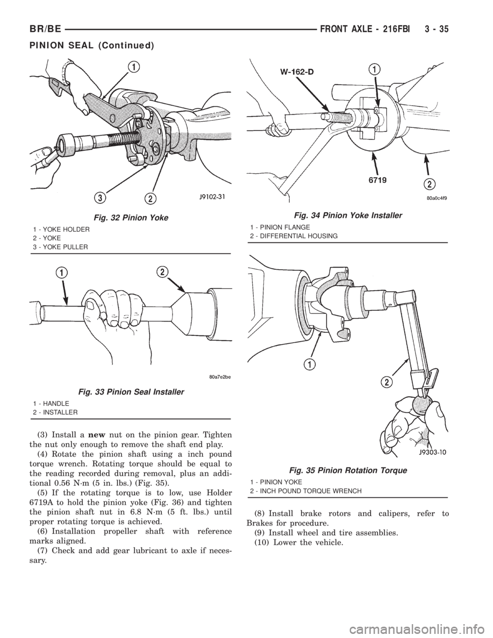
Remover C-452 and Flange Wrench C-3281 (Fig. 32).
(9) Remove pinion shaft seal with a pry tool or
slide hammer mounted screw.
INSTALLATION
(1) Apply a light coating of gear lubricant on the
lip of pinion seal. Install seal with an appropriate
installer (Fig. 33).
(2) Install yoke on the pinion gear with Installer
W-162-D (Fig. 34).
CAUTION: Do not exceed the minimum tightening
torque when installing the pinion yoke retaining
nut. Damage to collapsible spacer or bearings may
result.
Fig. 30 Axle Shaft U-Joint
1 - SHAFT YOKE
2 - BEARING CAP
3 - SNAP RINGS
4 - BEARING CAP
5 - SPINDLE YOKE
6 - BEARING
7 - BEARING CAP
8 - SNAP RINGS
9 - BEARING CAP
Fig. 31 Yoke Bearing Cap
1 - LARGE-DIAMETER SOCKET WRENCH
2 - VISE
3 - SMALL-DIAMETER SOCKET WRENCH
3 - 34 FRONT AXLE - 216FBIBR/BE
SINGLE CARDAN UNIVERSAL JOINTS (Continued)
Page 108 of 2889
(3) Install anewnut on the pinion gear. Tighten
the nut only enough to remove the shaft end play.
(4) Rotate the pinion shaft using a inch pound
torque wrench. Rotating torque should be equal to
the reading recorded during removal, plus an addi-
tional 0.56 N´m (5 in. lbs.) (Fig. 35).
(5) If the rotating torque is to low, use Holder
6719A to hold the pinion yoke (Fig. 36) and tighten
the pinion shaft nut in 6.8 N´m (5 ft. lbs.) until
proper rotating torque is achieved.
(6) Installation propeller shaft with reference
marks aligned.
(7) Check and add gear lubricant to axle if neces-
sary.(8) Install brake rotors and calipers, refer to
Brakes for procedure.
(9) Install wheel and tire assemblies.
(10) Lower the vehicle.
Fig. 32 Pinion Yoke
1 - YOKE HOLDER
2 - YOKE
3 - YOKE PULLER
Fig. 33 Pinion Seal Installer
1 - HANDLE
2 - INSTALLER
Fig. 34 Pinion Yoke Installer
1 - PINION FLANGE
2 - DIFFERENTIAL HOUSING
Fig. 35 Pinion Rotation Torque
1 - PINION YOKE
2 - INCH POUND TORQUE WRENCH
BR/BEFRONT AXLE - 216FBI 3 - 35
PINION SEAL (Continued)
Page 119 of 2889
mate and side gears. The side gears are splined to
the axle shafts.
During straight-ahead driving, the differential pin-
ion gears do not rotate on the pinion mate shaft. This
occurs because input torque applied to the gears is
divided and distributed equally between the two side
gears. As a result, the pinion gears revolve with the
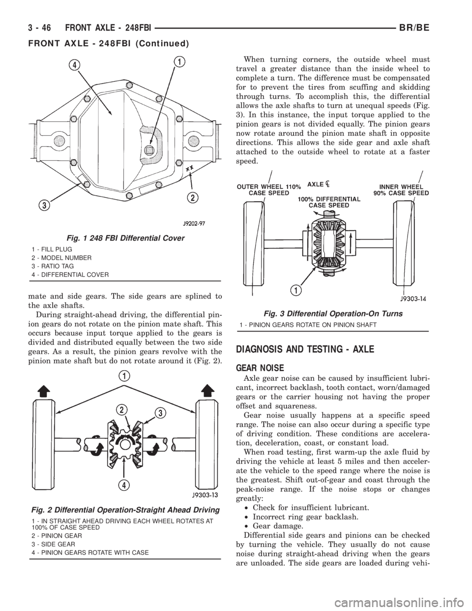
pinion mate shaft but do not rotate around it (Fig. 2).When turning corners, the outside wheel must
travel a greater distance than the inside wheel to
complete a turn. The difference must be compensated
for to prevent the tires from scuffing and skidding
through turns. To accomplish this, the differential
allows the axle shafts to turn at unequal speeds (Fig.
3). In this instance, the input torque applied to the
pinion gears is not divided equally. The pinion gears
now rotate around the pinion mate shaft in opposite
directions. This allows the side gear and axle shaft
attached to the outside wheel to rotate at a faster
speed.
DIAGNOSIS AND TESTING - AXLE
GEAR NOISE
Axle gear noise can be caused by insufficient lubri-
cant, incorrect backlash, tooth contact, worn/damaged
gears or the carrier housing not having the proper
offset and squareness.
Gear noise usually happens at a specific speed
range. The noise can also occur during a specific type
of driving condition. These conditions are accelera-
tion, deceleration, coast, or constant load.
When road testing, first warm-up the axle fluid by
driving the vehicle at least 5 miles and then acceler-
ate the vehicle to the speed range where the noise is
the greatest. Shift out-of-gear and coast through the
peak-noise range. If the noise stops or changes
greatly:
²Check for insufficient lubricant.
²Incorrect ring gear backlash.
²Gear damage.
Differential side gears and pinions can be checked
by turning the vehicle. They usually do not cause
noise during straight-ahead driving when the gears
are unloaded. The side gears are loaded during vehi-
Fig. 1 248 FBI Differential Cover
1 - FILL PLUG
2 - MODEL NUMBER
3 - RATIO TAG
4 - DIFFERENTIAL COVER
Fig. 2 Differential Operation-Straight Ahead Driving
1 - IN STRAIGHT AHEAD DRIVING EACH WHEEL ROTATES AT
100% OF CASE SPEED
2 - PINION GEAR
3 - SIDE GEAR
4 - PINION GEARS ROTATE WITH CASE
Fig. 3 Differential Operation-On Turns
1 - PINION GEARS ROTATE ON PINION SHAFT
3 - 46 FRONT AXLE - 248FBIBR/BE
FRONT AXLE - 248FBI (Continued)
Page 123 of 2889

REMOVAL
(1) Raise and support the vehicle.
(2) Remove the wheels and tires.
(3) Remove the brake calipers and rotors. Refer to
Group 5, Brakes, for proper procedures.
(4) Remove ABS wheel speed sensors, if equipped.
Refer to Group 5, Brakes, for proper procedures.
(5) Disconnect the axle vent hose.
(6) Disconnect vacuum hose and electrical connec-
tor at disconnect housing.
(7) Remove the front propeller shaft.
(8) Disconnect the stabilizer bar links at the axle
brackets.
(9) Disconnect the shock absorbers from axle
brackets.
(10) Disconnect the track bar from the axle
bracket.
(11) Disconnect the tie rod and drag link from the
steering knuckles.
(12) Position the axle with a suitable lifting device
under the axle assembly.
(13) Secure axle to lifting device.
(14) Mark suspension alignment cams for installa-
tion reference.
(15) Disconnect the upper and lower suspension
arms from the axle bracket.
(16) Lower the axle. The coil springs will drop
with the axle.
(17) Remove the coil springs from the axle bracket.
INSTALLATION
CAUTION: Suspension components with rubber
bushings should be tightened with the weight of the
vehicle on the suspension, at normal height. If
springs are not at their normal ride position, vehicle
ride comfort could be affected and premature bush-
ing wear may occur. Rubber bushings must never
be lubricated.
(1) Support the axle on a suitable lifting device.
(2) Secure axle to lifting device.
(3) Position the axle under the vehicle.
(4) Install the springs, retainer clip and bolts.
(5) Raise the axle and align it with the spring
pads.
(6) Position the upper and lower suspension arms
in the axle brackets. Install bolts, nuts and align the
suspension alignment cams to the reference marks.
Do not tighten at this time.
(7) Connect the track bar to the axle bracket and
install the bolt. Do not tighten at this time.
(8) Install the shock absorber and tighten bolts to
121 N´m (89 ft. lbs.) torque.(9) Install the stabilizer bar link to the axle
bracket. Tighten the nut to 37 N´m (27 ft. lbs.)
torque.
(10) Install the drag link and tie rod to the steer-
ing knuckles and tighten the nuts to 88 N´m (65 ft.
lbs.) torque.
(11) Install the ABS wheel speed sensors, if
equipped. Refer to group 5, Brakes, for proper proce-
dures.
(12) Install the brake calipers and rotors. Refer to
Group 5, Brakes, for proper procedures.
(13) Connect the vent hose to the tube fitting.
(14) Connect vacuum hose and electrical connector
to disconnect housing.
(15) Install front propeller shaft.
(16) Check and add differential lubricant, if neces-
sary. Refer to Lubricant Specifications in this section
for lubricant requirements.
(17) Install the wheel and tire assemblies.
(18) Remove the supports and lower the vehicle.
(19) Tighten the upper suspension arm nuts at
axle to 121 N´m (89 ft. lbs.) torque. Tighten the
upper suspension arm nuts at frame to 84 N´m (62 ft.
lbs.) torque.
(20) Tighten the lower suspension arm nuts at
axle to 84 N´m (62 ft. lbs.) torque. Tighten the lower
suspension arm nuts at frame to 119 N´m (88 ft. lbs.)
torque.
(21) Tighten the track bar bolt at the axle bracket
to 176 N´m (130 ft. lbs.) torque.
(22) Check the front wheel alignment.ADJUSTMENTS
Ring and pinion gears are supplied as matched
sets only. The identifying numbers for the ring and
pinion gear are etched into the face of each gear (Fig.
4). A plus (+) number, minus (±) number or zero (0) is
etched into the face of the pinion gear. This number
is the amount (in thousandths of an inch) the depth
varies from the standard depth setting of a pinion
etched with a (0). The standard setting from the cen-
ter line of the ring gear to the back face of the pinion
is 127 mm (5.00 in.). The standard depth provides
the best gear tooth contact pattern. Refer to Back-
lash and Contact Pattern in this section for addi-
tional information.
Compensation for pinion depth variance is
achieved with a select shim/oil baffle. The shims are
placed between the rear pinion bearing and the pin-
ion gear head (Fig. 5).
If a new gear set is being installed, note the depth
variance etched into both the original and replace-
ment pinion. Add or subtract this number from the
thickness of the original depth shim/oil slinger to
compensate for the difference in the depth variances.
Refer to the Depth Variance chart.
3 - 50 FRONT AXLE - 248FBIBR/BE
FRONT AXLE - 248FBI (Continued)
Page 139 of 2889
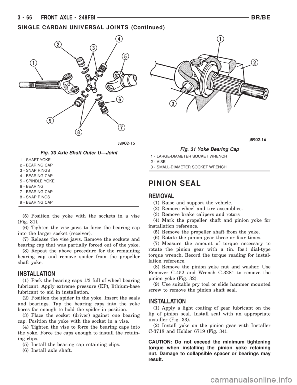
(5) Position the yoke with the sockets in a vise
(Fig. 31).
(6) Tighten the vise jaws to force the bearing cap
into the larger socket (receiver).
(7) Release the vise jaws. Remove the sockets and
bearing cap that was partially forced out of the yoke.
(8) Repeat the above procedure for the remaining
bearing cap and remove spider from the propeller
shaft yoke.
INSTALLATION
(1) Pack the bearing caps 1/3 full of wheel bearing
lubricant. Apply extreme pressure (EP), lithium-base
lubricant to aid in installation.
(2) Position the spider in the yoke. Insert the seals
and bearings. Tap the bearing caps into the yoke
bores far enough to hold the spider in position.
(3) Place the socket (driver) against one bearing
cap. Position the yoke with the socket in a vise.
(4) Tighten the vise to force the bearing caps into
the yoke. Force the caps enough to install the retain-
ing clips.
(5) Install the bearing cap retaining clips.
(6) Install axle shaft.
PINION SEAL
REMOVAL
(1) Raise and support the vehicle.
(2) Remove wheel and tire assemblies.
(3) Remove brake calipers and rotors
(4) Mark the propeller shaft and pinion yoke for
installation reference.
(5) Remove the propeller shaft from the yoke.
(6) Rotate the pinion gear three or four times.
(7) Measure the amount of torque necessary to
rotate the pinion gear with a (in. lbs.) dial-type
torque wrench. Record the torque reading for instal-
lation reference.
(8) Remove the pinion yoke nut and washer. Use
Remover C-452 and Wrench C-3281 to remove the
pinion yoke (Fig. 32).
(9) Use suitable pry tool or slide hammer mounted
screw to remove the pinion shaft seal.
INSTALLATION
(1) Apply a light coating of gear lubricant on the
lip of pinion seal. Install seal with an appropriate
installer (Fig. 33).
(2) Install yoke on the pinion gear with Installer
C-3718 and Holder 6719 (Fig. 34).
CAUTION: Do not exceed the minimum tightening
torque when installing the pinion yoke retaining
nut. Damage to collapsible spacer or bearings may
result.
Fig. 30 Axle Shaft Outer UÐJoint
1 - SHAFT YOKE
2 - BEARING CAP
3 - SNAP RINGS
4 - BEARING CAP
5 - SPINDLE YOKE
6 - BEARING
7 - BEARING CAP
8 - SNAP RINGS
9 - BEARING CAP
Fig. 31 Yoke Bearing Cap
1 - LARGE-DIAMETER SOCKET WRENCH
2 - VISE
3 - SMALL-DIAMETER SOCKET WRENCH
3 - 66 FRONT AXLE - 248FBIBR/BE
SINGLE CARDAN UNIVERSAL JOINTS (Continued)
Page 140 of 2889
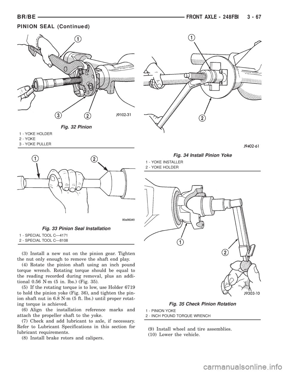
(3) Install a new nut on the pinion gear. Tighten
the nut only enough to remove the shaft end play.
(4) Rotate the pinion shaft using an inch pound
torque wrench. Rotating torque should be equal to
the reading recorded during removal, plus an addi-
tional 0.56 N´m (5 in. lbs.) (Fig. 35).
(5) If the rotating torque is to low, use Holder 6719
to hold the pinion yoke (Fig. 36), and tighten the pin-
ion shaft nut in 6.8 N´m (5 ft. lbs.) until proper rotat-
ing torque is achieved.
(6) Align the installation reference marks and
attach the propeller shaft to the yoke.
(7) Check and add lubricant to axle, if necessary.
Refer to Lubricant Specifications in this section for
lubricant requirements.
(8) Install brake rotors and calipers.(9) Install wheel and tire assemblies.
(10) Lower the vehicle.
Fig. 32 Pinion
1 - YOKE HOLDER
2 - YOKE
3 - YOKE PULLER
Fig. 33 Pinion Seal Installation
1 - SPECIAL TOOL CÐ4171
2 - SPECIAL TOOL CÐ8108
Fig. 34 Install Pinion Yoke
1 - YOKE INSTALLER
2 - YOKE HOLDER
Fig. 35 Check Pinion Rotation
1 - PINION YOKE
2 - INCH POUND TORQUE WRENCH
BR/BEFRONT AXLE - 248FBI 3 - 67
PINION SEAL (Continued)
Page 152 of 2889
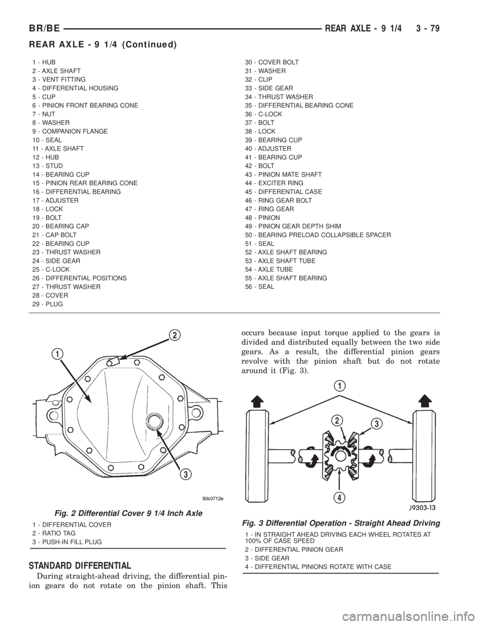
STANDARD DIFFERENTIAL
During straight-ahead driving, the differential pin-
ion gears do not rotate on the pinion shaft. Thisoccurs because input torque applied to the gears is
divided and distributed equally between the two side
gears. As a result, the differential pinion gears
revolve with the pinion shaft but do not rotate
around it (Fig. 3).
1 - HUB
2 - AXLE SHAFT
3 - VENT FITTING
4 - DIFFERENTIAL HOUSING
5 - CUP
6 - PINION FRONT BEARING CONE
7 - NUT
8 - WASHER
9 - COMPANION FLANGE
10 - SEAL
11 - AXLE SHAFT
12 - HUB
13 - STUD
14 - BEARING CUP
15 - PINION REAR BEARING CONE
16 - DIFFERENTIAL BEARING
17 - ADJUSTER
18 - LOCK
19 - BOLT
20 - BEARING CAP
21 - CAP BOLT
22 - BEARING CUP
23 - THRUST WASHER
24 - SIDE GEAR
25 - C-LOCK
26 - DIFFERENTIAL POSITIONS
27 - THRUST WASHER
28 - COVER
29 - PLUG30 - COVER BOLT
31 - WASHER
32 - CLIP
33 - SIDE GEAR
34 - THRUST WASHER
35 - DIFFERENTIAL BEARING CONE
36 - C-LOCK
37 - BOLT
38 - LOCK
39 - BEARING CUP
40 - ADJUSTER
41 - BEARING CUP
42 - BOLT
43 - PINION MATE SHAFT
44 - EXCITER RING
45 - DIFFERENTIAL CASE
46 - RING GEAR BOLT
47 - RING GEAR
48 - PINION
49 - PINION GEAR DEPTH SHIM
50 - BEARING PRELOAD COLLAPSIBLE SPACER
51 - SEAL
52 - AXLE SHAFT BEARING
53 - AXLE SHAFT TUBE
54 - AXLE TUBE
55 - AXLE SHAFT BEARING
56 - SEAL
Fig. 2 Differential Cover 9 1/4 Inch Axle
1 - DIFFERENTIAL COVER
2 - RATIO TAG
3 - PUSH-IN FILL PLUGFig. 3 Differential Operation - Straight Ahead Driving
1 - IN STRAIGHT AHEAD DRIVING EACH WHEEL ROTATES AT
100% OF CASE SPEED
2 - DIFFERENTIAL PINION GEAR
3 - SIDE GEAR
4 - DIFFERENTIAL PINIONS ROTATE WITH CASE
BR/BEREAR AXLE - 9 1/4 3 - 79
REAR AXLE - 9 1/4 (Continued)
Page 153 of 2889
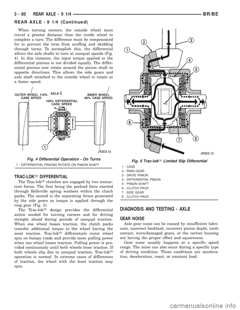
When turning corners, the outside wheel must
travel a greater distance than the inside wheel to
complete a turn. The difference must be compensated
for to prevent the tires from scuffing and skidding
through turns. To accomplish this, the differential
allows the axle shafts to turn at unequal speeds (Fig.
4). In this instance, the input torque applied to the
differential pinions is not divided equally. The differ-
ential pinions now rotate around the pinion shaft in
opposite directions. This allows the side gears and
axle shaft attached to the outside wheel to rotate at
a faster speed.
TRAC-LOKYDIFFERENTIAL
The Trac-lokyclutches are engaged by two concur-
rent forces. The first being the preload force exerted
through Belleville spring washers within the clutch
packs. The second is the separating forces generated
by the side gears as torque is applied through the
ring gear (Fig. 5).
The Trac-lokydesign provides the differential
action needed for turning corners and for driving
straight ahead during periods of unequal traction.
When one wheel looses traction, the clutch packs
transfer additional torque to the wheel having the
most traction. Trac-lokydifferentials resist wheel
spin on bumpy roads and provide more pulling power
when one wheel looses traction. Pulling power is pro-
vided continuously until both wheels loose traction. If
both wheels slip due to unequal traction, Trac-loky
operation is normal. In extreme cases of differences
of traction, the wheel with the least traction may
spin.
DIAGNOSIS AND TESTING - AXLE
GEAR NOISE
Axle gear noise can be caused by insufficient lubri-
cant, incorrect backlash, incorrect pinion depth, tooth
contact, worn/damaged gears, or the carrier housing
not having the proper offset and squareness.
Gear noise usually happens at a specific speed
range. The noise can also occur during a specific type
of driving condition. These conditions are accelera-
tion, deceleration, coast, or constant load.
Fig. 4 Differential Operation - On Turns
1 - DIFFERENTIAL PINIONS ROTATE ON PINION SHAFTFig. 5 Trac-lokYLimited Slip Differential
1 - CASE
2 - RING GEAR
3 - DRIVE PINION
4 - DIFFERENTIAL PINION
5 - PINION SHAFT
6 - CLUTCH PACK
7 - SIDE GEAR
8 - CLUTCH PACK
3 - 80 REAR AXLE-91/4BR/BE
REAR AXLE - 9 1/4 (Continued)