2001 DODGE RAM drain bolt
[x] Cancel search: drain boltPage 1640 of 2889
DISASSEMBLY
FRONT HOUSING
(1) Shift transmission into Neutral.
(2) If lubricant was not drained out of transmis-
sion during removal, remove drain plug and drain
lubricant.
(3) Inspect drain plug magnet for debris.
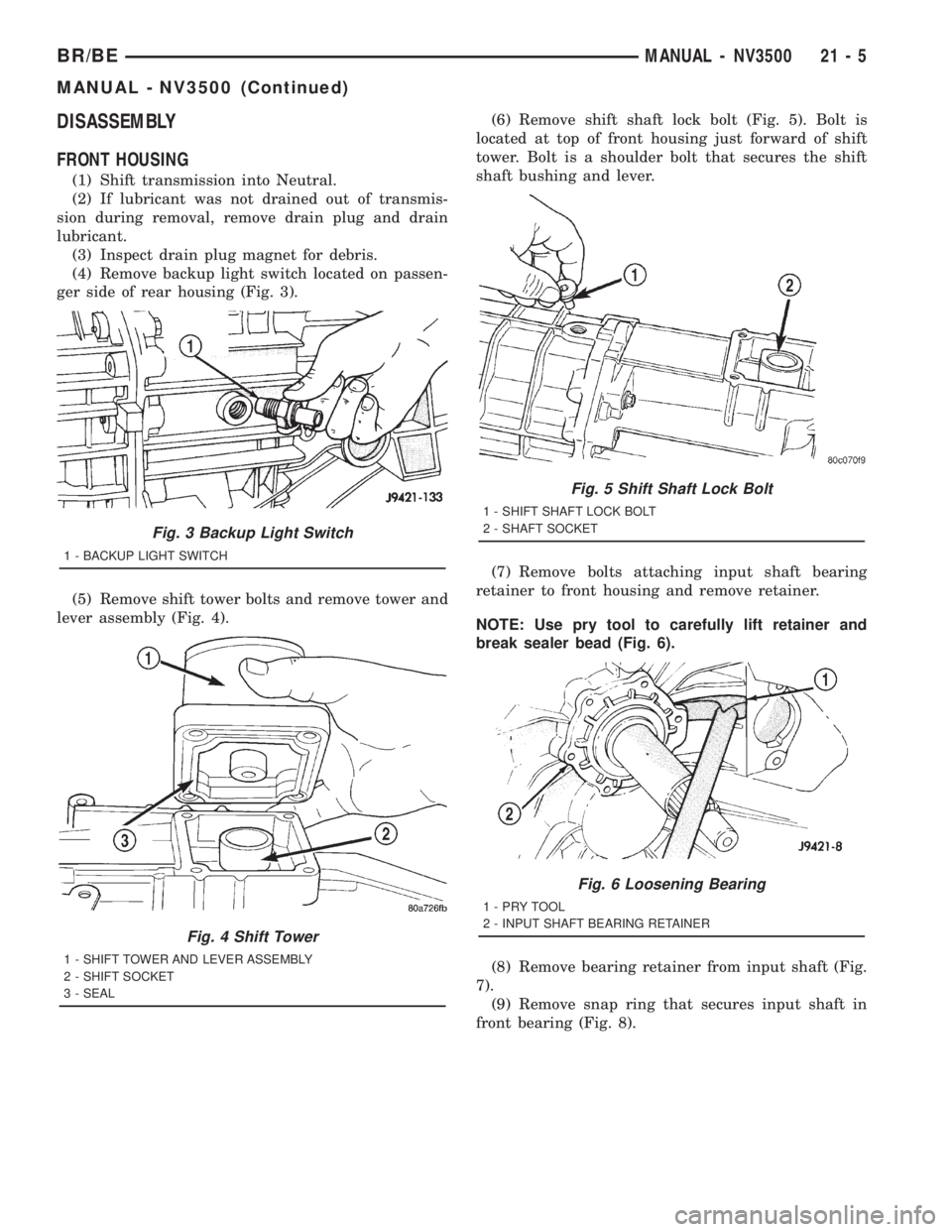
(4) Remove backup light switch located on passen-
ger side of rear housing (Fig. 3).
(5) Remove shift tower bolts and remove tower and
lever assembly (Fig. 4).(6) Remove shift shaft lock bolt (Fig. 5). Bolt is
located at top of front housing just forward of shift
tower. Bolt is a shoulder bolt that secures the shift
shaft bushing and lever.
(7) Remove bolts attaching input shaft bearing
retainer to front housing and remove retainer.
NOTE: Use pry tool to carefully lift retainer and
break sealer bead (Fig. 6).
(8) Remove bearing retainer from input shaft (Fig.
7).
(9) Remove snap ring that secures input shaft in
front bearing (Fig. 8).
Fig. 3 Backup Light Switch
1 - BACKUP LIGHT SWITCH
Fig. 4 Shift Tower
1 - SHIFT TOWER AND LEVER ASSEMBLY
2 - SHIFT SOCKET
3 - SEAL
Fig. 5 Shift Shaft Lock Bolt
1 - SHIFT SHAFT LOCK BOLT
2 - SHAFT SOCKET
Fig. 6 Loosening Bearing
1-PRYTOOL
2 - INPUT SHAFT BEARING RETAINER
BR/BEMANUAL - NV3500 21 - 5
MANUAL - NV3500 (Continued)
Page 1676 of 2889
SPECIFICATIONS
MANUAL - NV3500
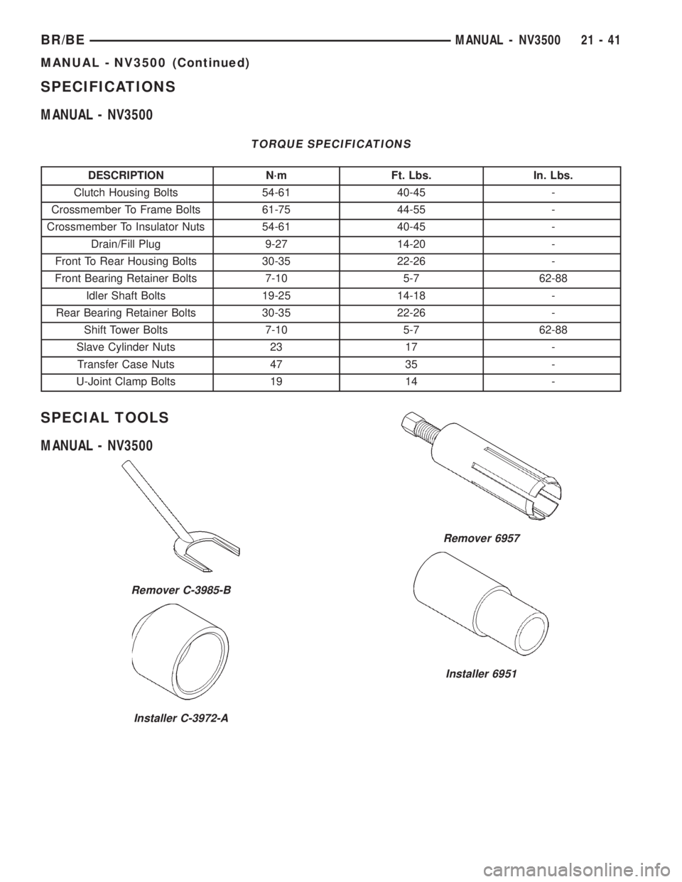
TORQUE SPECIFICATIONS
DESCRIPTION N´m Ft. Lbs. In. Lbs.
Clutch Housing Bolts 54-61 40-45 -
Crossmember To Frame Bolts 61-75 44-55 -
Crossmember To Insulator Nuts 54-61 40-45 -
Drain/Fill Plug 9-27 14-20 -
Front To Rear Housing Bolts 30-35 22-26 -
Front Bearing Retainer Bolts 7-10 5-7 62-88
Idler Shaft Bolts 19-25 14-18 -
Rear Bearing Retainer Bolts 30-35 22-26 -
Shift Tower Bolts 7-10 5-7 62-88
Slave Cylinder Nuts 23 17 -
Transfer Case Nuts 47 35 -
U-Joint Clamp Bolts 19 14 -
SPECIAL TOOLS
MANUAL - NV3500
Remover C-3985-B
Installer C-3972-A
Remover 6957
Installer 6951
BR/BEMANUAL - NV3500 21 - 41
MANUAL - NV3500 (Continued)
Page 1682 of 2889
A leak at the front of the transmission will be from
either the front bearing retainer or retainer seal.
Lubricant may be seen dripping from the clutch
housing after extended operation. If the leak is
severe, it may also contaminate the clutch disc caus-
ing the disc to slip, grab and or chatter.
A correct lubricant level check can only be made
when the vehicle is level. Also allow the lubricant to
settle for a minute or so before checking. These rec-
ommendations will ensure an accurate check and
avoid an underfill or overfill condition. Always check
the lubricant level after any addition of fluid to avoid
an incorrect lubricant level condition.
HARD SHIFTING
Hard shifting is usually caused by a low lubricant
level, improper or contaminated lubricants. The con-
sequence of using non-recommended lubricants is
noise, excessive wear, internal bind and hard shift-
ing. Substantial lubricant leaks can result in gear,
shift rail, synchro, and bearing damage. If a leak
goes undetected for an extended period, the first indi-
cations of component damage are usually hard shift-
ing and noise.
Component damage, incorrect clutch adjustment or
damaged clutch pressure plate or disc are additional
probable causes of increased shift effort. Incorrect
adjustment or a worn/damaged pressure plate or disc
can cause incorrect release. If clutch problem is
advanced, gear clash during shifts can result. Worn
or damaged synchro rings can cause gear clash when
shifting into any forward gear. In some new or
rebuilt transmissions, new synchro rings may tend to
stick slightly causing hard or noisy shifts. In most
cases this condition will decline as the rings wear-in.
TRANSMISSION NOISE
Most manual transmissions make some noise dur-
ing normal operation. Rotating gears generate a mild
whine that is audible, but generally only at extreme
speeds.
Severe highly audible transmission noise is gener-
ally the initial indicator of a lubricant problem.
Insufficient, improper or contaminated lubricant will
promote rapid wear of gears, synchros, shift rails,
forks and bearings. The overheating caused by a
lubricant problem, can also lead to gear breakage.
REMOVAL
(1) Disconnect battery negative cable.
(2) Shift transmission into Neutral.
(3) Remove shift boot screws from floorpan and
slide boot upward on the shift lever.
(4) Remove shift lever extension from shift tower
and lever assembly.(5) Remove shift tower bolts holding tower to iso-
lator plate and transmission shift cover.
(6) Remove shift tower and isolator plate from
transmission shift cover.
(7) Raise and support vehicle.
(8) Remove skid plate, if equipped.
(9) Mark propeller shaft and axle yokes for instal-
lation reference and remove shaft/shafts.
(10) Remove exhaust system Y-pipe.
(11) Disconnect speed sensor and backup light
switch connectors.
(12) Support engine with safety stand and a wood
block.
(13) If transmission is to be disassembled for,
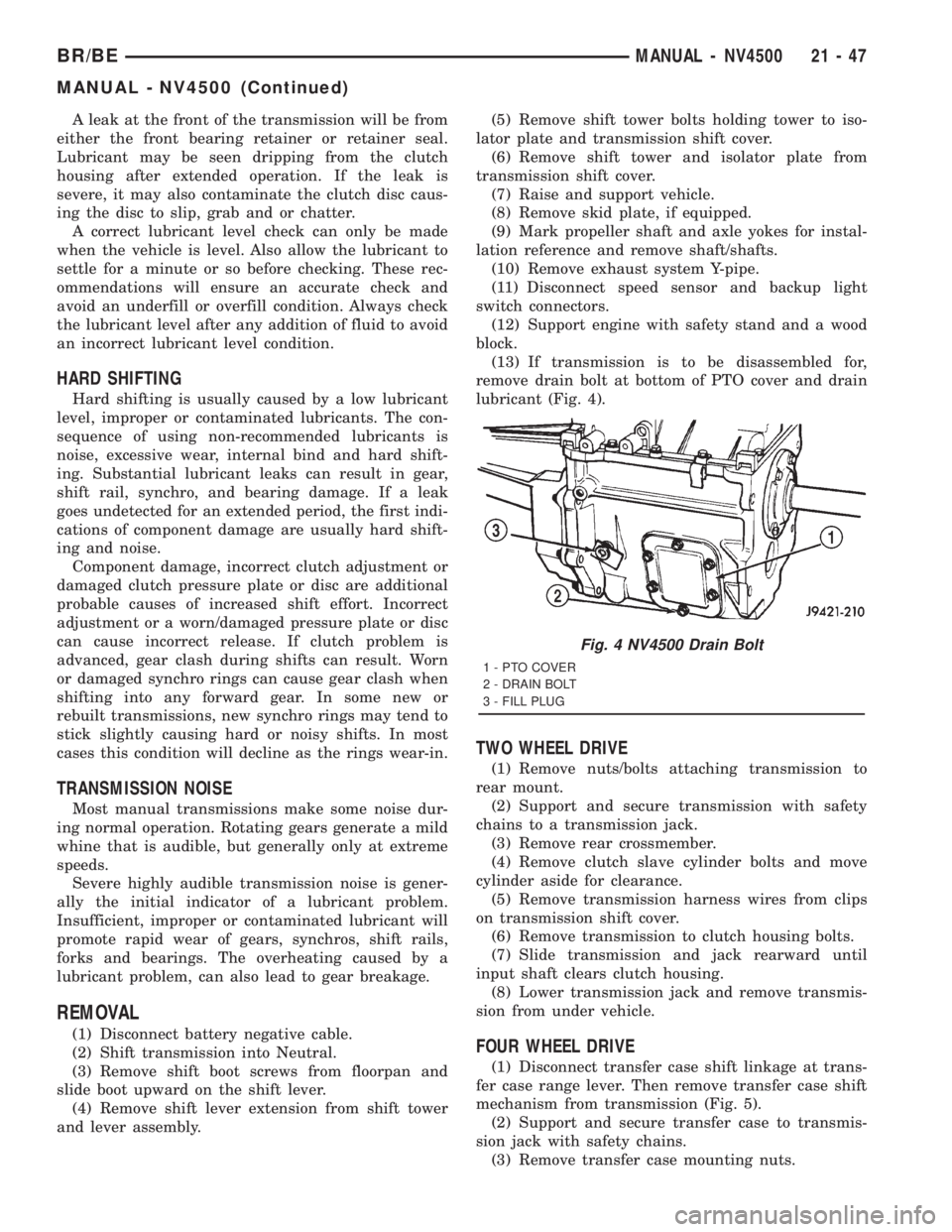
remove drain bolt at bottom of PTO cover and drain
lubricant (Fig. 4).
TWO WHEEL DRIVE
(1) Remove nuts/bolts attaching transmission to
rear mount.
(2) Support and secure transmission with safety
chains to a transmission jack.
(3) Remove rear crossmember.
(4) Remove clutch slave cylinder bolts and move
cylinder aside for clearance.
(5) Remove transmission harness wires from clips
on transmission shift cover.
(6) Remove transmission to clutch housing bolts.
(7) Slide transmission and jack rearward until
input shaft clears clutch housing.
(8) Lower transmission jack and remove transmis-
sion from under vehicle.
FOUR WHEEL DRIVE
(1) Disconnect transfer case shift linkage at trans-
fer case range lever. Then remove transfer case shift
mechanism from transmission (Fig. 5).
(2) Support and secure transfer case to transmis-
sion jack with safety chains.
(3) Remove transfer case mounting nuts.
Fig. 4 NV4500 Drain Bolt
1 - PTO COVER
2 - DRAIN BOLT
3 - FILL PLUG
BR/BEMANUAL - NV4500 21 - 47
MANUAL - NV4500 (Continued)
Page 1718 of 2889
(18) Install the bolts to hold the shift tower to the
isolator plate and the shift cover. Tighten the shift
tower bolts to 10.2±11.25 N´m (7.5±8.3 ft. lbs.).
(19) Install the shift lever extension onto the shift
tower and lever assembly.(20) Install shift lever boot and bezel.
(21) Connect battery negative cable.
SPECIFICATIONS
SPECIFICATIONS - NV4500
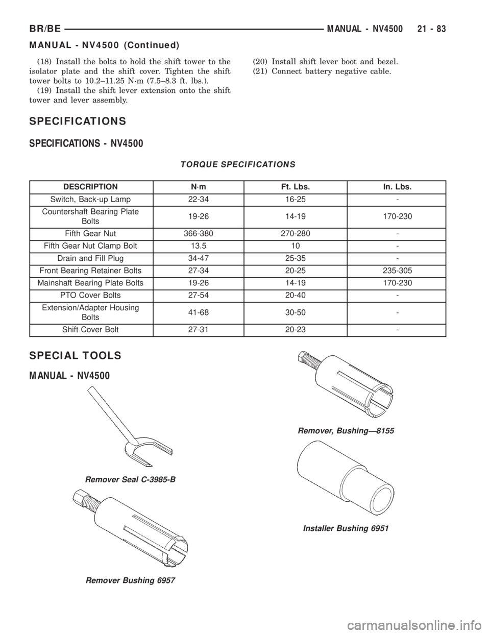
TORQUE SPECIFICATIONS
DESCRIPTION N´m Ft. Lbs. In. Lbs.
Switch, Back-up Lamp 22-34 16-25 -
Countershaft Bearing Plate
Bolts19-26 14-19 170-230
Fifth Gear Nut 366-380 270-280 -
Fifth Gear Nut Clamp Bolt 13.5 10 -
Drain and Fill Plug 34-47 25-35 -
Front Bearing Retainer Bolts 27-34 20-25 235-305
Mainshaft Bearing Plate Bolts 19-26 14-19 170-230
PTO Cover Bolts 27-54 20-40 -
Extension/Adapter Housing
Bolts41-68 30-50 -
Shift Cover Bolt 27-31 20-23 -
SPECIAL TOOLS
MANUAL - NV4500
Remover Seal C-3985-B
Remover Bushing 6957
Remover, BushingÐ8155
Installer Bushing 6951
BR/BEMANUAL - NV4500 21 - 83
MANUAL - NV4500 (Continued)
Page 1729 of 2889
A leak at the front of the transmission will be from
either the front bearing retainer or retainer seal.
Lubricant may be seen dripping from the clutch
housing after extended operation. If the leak is
severe, it may also contaminate the clutch disc caus-
ing the disc to slip, grab and or chatter.
A correct lubricant level check can only be made
when the vehicle is level. Also allow the lubricant to
settle for a minute or so before checking. These rec-
ommendations will ensure an accurate check and
avoid an underfill or overfill condition. Always check
the lubricant level after any addition of fluid to avoid
an incorrect lubricant level condition.
HARD SHIFTING
Hard shifting is usually caused by a low lubricant
level, improper or contaminated lubricants. The con-
sequence of using non-recommended lubricants is
noise, excessive wear, internal bind and hard shift-
ing. Substantial lubricant leaks can result in gear,
shift rail, synchro, and bearing damage. If a leak
goes undetected for an extended period, the first indi-
cations of component damage are usually hard shift-
ing and noise.
Component damage, incorrect clutch adjustment or
damaged clutch pressure plate or disc are additional
probable causes of increased shift effort. Incorrect
adjustment or a worn/damaged pressure plate or disc
can cause incorrect release. If clutch problem is
advanced, gear clash during shifts can result. Worn
or damaged synchro rings can cause gear clash when
shifting into any forward gear. In some new or
rebuilt transmissions, new synchro rings may tend to
stick slightly causing hard or noisy shifts. In most
cases this condition will decline as the rings wear-in.
TRANSMISSION NOISE
Most manual transmissions make some noise dur-
ing normal operation. Rotating gears generate a mild
whine that is audible, but generally only at extreme
speeds.
Severe highly audible transmission noise is gener-
ally the initial indicator of a lubricant problem.
Insufficient, improper or contaminated lubricant will
promote rapid wear of gears, synchros, shift rails,
forks and bearings. The overheating caused by a
lubricant problem, can also lead to gear breakage.
REMOVAL
NOTE: Use a heavy duty scissors style transmis-
sion jack for remove of the transmission.
(1) Disconnect battery negative cable.
(2) Shift transmission into Neutral.
(3) Remove screws attaching shift boot to floorpan.
Then slide boot upward on the shift lever.(4) Remove the bolts holding the shift tower to the
isolator plate and transmission gear case.
(5) Remove the shift tower and isolator plate from
the transmission gear case.
(6) Raise and support vehicle.
(7) Remove skid plate, if equipped.
(8) Mark propeller shaft/shafts and axle yokes for
installation reference.
(9) Remove propeller shaft.
(10) Disconnect and remove exhaust system as
necessary.
(11) Disconnect wires at backup light switch.
(12) Support engine with adjustable safety stand
and wood block.
(13) If transmission is to be disassembled for
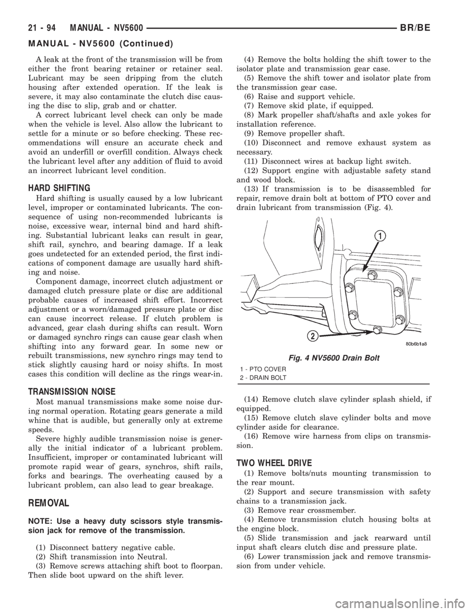
repair, remove drain bolt at bottom of PTO cover and
drain lubricant from transmission (Fig. 4).
(14) Remove clutch slave cylinder splash shield, if
equipped.
(15) Remove clutch slave cylinder bolts and move
cylinder aside for clearance.
(16) Remove wire harness from clips on transmis-
sion.
TWO WHEEL DRIVE
(1) Remove bolts/nuts mounting transmission to
the rear mount.
(2) Support and secure transmission with safety
chains to a transmission jack.
(3) Remove rear crossmember.
(4) Remove transmission clutch housing bolts at
the engine block.
(5) Slide transmission and jack rearward until
input shaft clears clutch disc and pressure plate.
(6) Lower transmission jack and remove transmis-
sion from under vehicle.
Fig. 4 NV5600 Drain Bolt
1 - PTO COVER
2 - DRAIN BOLT
21 - 94 MANUAL - NV5600BR/BE
MANUAL - NV5600 (Continued)
Page 1759 of 2889
EXTENSION/ADAPTER HOUSING
(1) Install extension housing bushing with
Installer 8156 and Handle C-4171, if necessary. The
oil feed hole must be at the 12 o'clock position when
installed.
(2) On 4X2 vehicles, install extension housing seal
with Installer 8154 and Handle C-4171, with the
weep hole at the bottom.
NOTE: Drain hole located in the dust boot portion
of the seal must face downward ( toward the
ground) when installed.
(3) On 4X4 vehicles, install adapter housing seal
with Installer C-3860-A and Handle C-4171.
(4) Install the crossover cam bushing into the
extension/adapter housing with Installer 8239 and
Handle C-4171.
(5) Clean the rear of the transmission case of all
sealer.
(6) Install reverse countershaft gear bearing race
onto the reverse countershaft gear bearing.
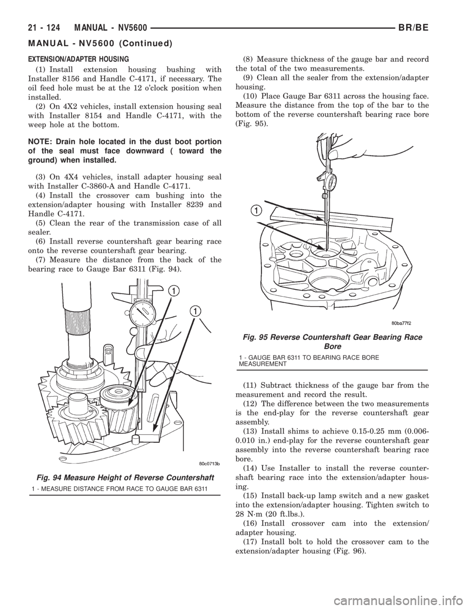
(7) Measure the distance from the back of the
bearing race to Gauge Bar 6311 (Fig. 94).(8) Measure thickness of the gauge bar and record
the total of the two measurements.
(9) Clean all the sealer from the extension/adapter
housing.
(10) Place Gauge Bar 6311 across the housing face.
Measure the distance from the top of the bar to the
bottom of the reverse countershaft bearing race bore
(Fig. 95).
(11) Subtract thickness of the gauge bar from the
measurement and record the result.
(12) The difference between the two measurements
is the end-play for the reverse countershaft gear
assembly.
(13) Install shims to achieve 0.15-0.25 mm (0.006-
0.010 in.) end-play for the reverse countershaft gear
assembly into the reverse countershaft bearing race
bore.
(14) Use Installer to install the reverse counter-
shaft bearing race into the extension/adapter hous-
ing.
(15) Install back-up lamp switch and a new gasket
into the extension/adapter housing. Tighten switch to
28 N´m (20 ft.lbs.).
(16) Install crossover cam into the extension/
adapter housing.
(17) Install bolt to hold the crossover cam to the
extension/adapter housing (Fig. 96).
Fig. 94 Measure Height of Reverse Countershaft
1 - MEASURE DISTANCE FROM RACE TO GAUGE BAR 6311
Fig. 95 Reverse Countershaft Gear Bearing Race
Bore
1 - GAUGE BAR 6311 TO BEARING RACE BORE
MEASUREMENT
21 - 124 MANUAL - NV5600BR/BE
MANUAL - NV5600 (Continued)
Page 1783 of 2889
Piston movement can be felt and a soft thump heard
as the clutch applies.
Front Servo Apply Air Test
Apply air pressure to the front servo apply pas-
sage. The servo rod should extend and cause the
band to tighten around the drum. Spring pressure
should release the servo when air pressure is
removed.
Rear Servo Air Test
Apply air pressure to the rear servo apply passage.
The servo rod should extend and cause the band to
tighten around the drum. Spring pressure should
release the servo when air pressure is removed.
DIAGNOSIS AND TESTING - CONVERTER
HOUSING FLUID LEAK
When diagnosing converter housing fluid leaks,
two items must be established before repair.
(1) Verify that a leak condition actually exists.
(2) Determined the true source of the leak.
Some suspected converter housing fluid leaks may
not be leaks at all. They may only be the result of
residual fluid in the converter housing, or excess
fluid spilled during factory fill or fill after repair.
Converter housing leaks have several potential
sources. Through careful observation, a leak source
can be identified before removing the transmission
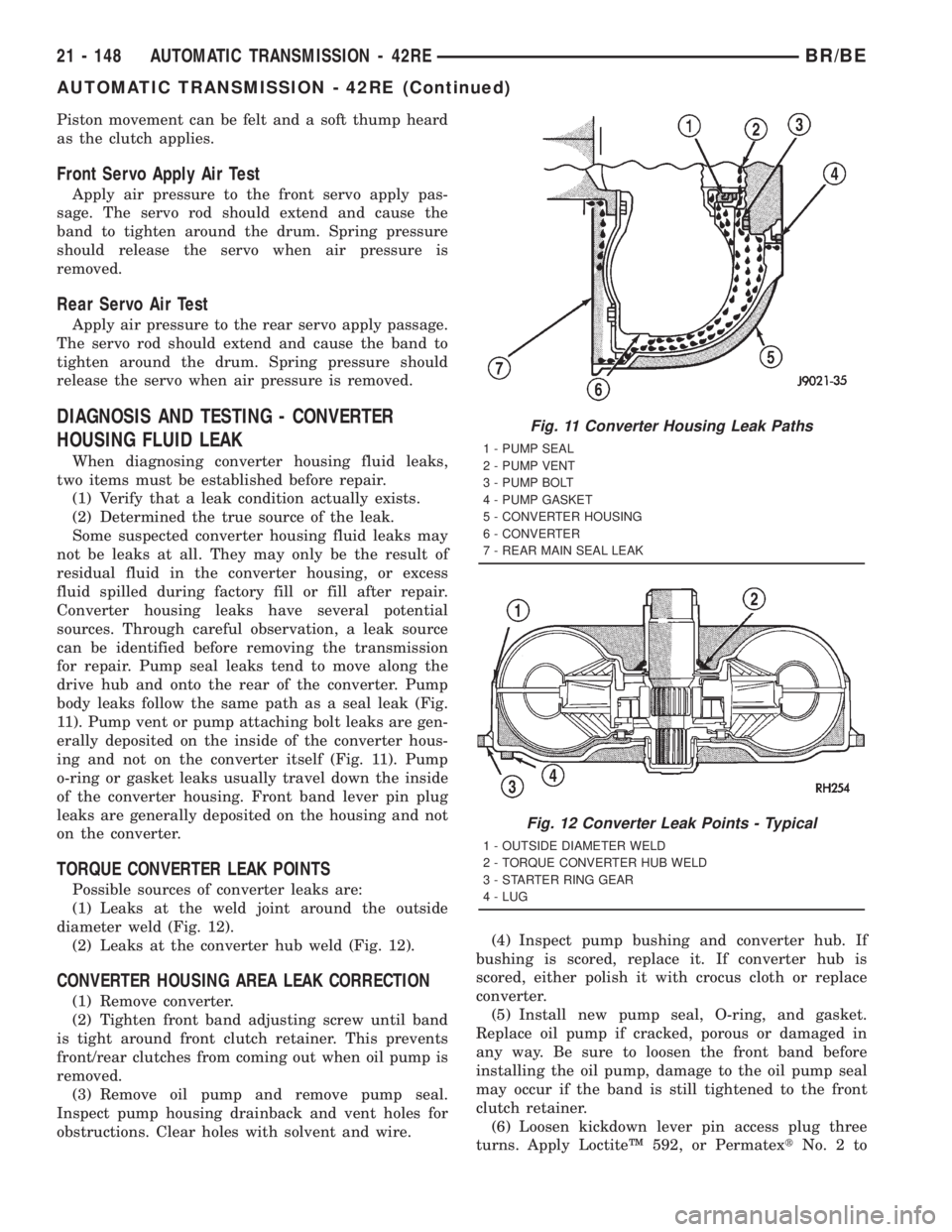
for repair. Pump seal leaks tend to move along the
drive hub and onto the rear of the converter. Pump
body leaks follow the same path as a seal leak (Fig.
11). Pump vent or pump attaching bolt leaks are gen-
erally deposited on the inside of the converter hous-
ing and not on the converter itself (Fig. 11). Pump
o-ring or gasket leaks usually travel down the inside
of the converter housing. Front band lever pin plug
leaks are generally deposited on the housing and not
on the converter.
TORQUE CONVERTER LEAK POINTS
Possible sources of converter leaks are:
(1) Leaks at the weld joint around the outside
diameter weld (Fig. 12).
(2) Leaks at the converter hub weld (Fig. 12).
CONVERTER HOUSING AREA LEAK CORRECTION
(1) Remove converter.
(2) Tighten front band adjusting screw until band
is tight around front clutch retainer. This prevents
front/rear clutches from coming out when oil pump is
removed.
(3) Remove oil pump and remove pump seal.
Inspect pump housing drainback and vent holes for
obstructions. Clear holes with solvent and wire.(4) Inspect pump bushing and converter hub. If
bushing is scored, replace it. If converter hub is
scored, either polish it with crocus cloth or replace
converter.
(5) Install new pump seal, O-ring, and gasket.
Replace oil pump if cracked, porous or damaged in
any way. Be sure to loosen the front band before
installing the oil pump, damage to the oil pump seal
may occur if the band is still tightened to the front
clutch retainer.
(6) Loosen kickdown lever pin access plug three
turns. Apply LoctiteŸ 592, or PermatextNo.2to
Fig. 11 Converter Housing Leak Paths
1 - PUMP SEAL
2 - PUMP VENT
3 - PUMP BOLT
4 - PUMP GASKET
5 - CONVERTER HOUSING
6 - CONVERTER
7 - REAR MAIN SEAL LEAK
Fig. 12 Converter Leak Points - Typical
1 - OUTSIDE DIAMETER WELD
2 - TORQUE CONVERTER HUB WELD
3 - STARTER RING GEAR
4 - LUG
21 - 148 AUTOMATIC TRANSMISSION - 42REBR/BE
AUTOMATIC TRANSMISSION - 42RE (Continued)
Page 1794 of 2889
CONDITION POSSIBLE CAUSES CORRECTION
11. Pump Seal Leaks/Worn/
Damaged.11. Replace seal.
12. Torque Converter Weld
Leak/Cracked Hub.12. Replace converter.
13. Case Porosity Leaks. 13. Replace case.
NOISY OPERATION IN
FOURTH GEAR ONLY1. Overdrive Clutch Discs, Plates or
Snap Rings Damaged.1. Remove unit and rebuild clutch pack.
2. Overdrive Piston or Planetary
Thrust Bearing Damaged.2. Remove and disassemble unit. Replace
either thrust bearing if damaged.
3. Output Shaft Bearings Scored/
Damaged.3. Remove and disassemble unit. Replace
either bearing if damaged.
4. Planetary Gears Worn/Chipped. 4. Remove and overhaul overdrive unit.
5. Overdrive Unit Overrunning Clutch
Rollers Worn/Scored.5. Remove and overhaul overdrive unit.
STANDARD PROCEDURE - ALUMINUM
THREAD REPAIR
Damaged or worn threads in the aluminum trans-
mission case and valve body can be repaired by the
use of Heli-CoilsŸ, or equivalent. This repair con-
sists of drilling out the worn-out damaged threads.
Then tap the hole with a special Heli-CoilŸ tap, or
equivalent, and installing a Heli-CoilŸ insert, or
equivalent, into the hole. This brings the hole back to
its original thread size.
Heli-CoilŸ, or equivalent, tools and inserts are
readily available from most automotive parts suppliers.
REMOVAL
The overdrive unit can be removed and serviced
separately. It is not necessary to remove the entire
transmission assembly to perform overdrive unit
repairs.
(1) Disconnect battery negative cable.
(2) Disconnect and lower or remove necessary
exhaust components.
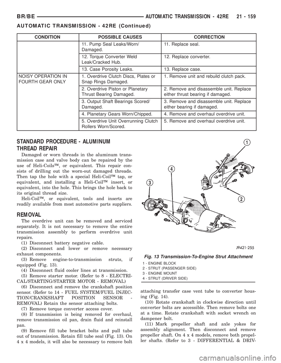
(3) Remove engine-to-transmission struts, if
equipped (Fig. 13).
(4) Disconnect fluid cooler lines at transmission.
(5) Remove starter motor. (Refer to 8 - ELECTRI-
CAL/STARTING/STARTER MOTOR - REMOVAL)
(6) Disconnect and remove the crankshaft position
sensor. (Refer to 14 - FUEL SYSTEM/FUEL INJEC-
TION/CRANKSHAFT POSITION SENSOR -
REMOVAL) Retain the sensor attaching bolts.
(7) Remove torque converter access cover.
(8)
If transmission is being removed for overhaul,
remove transmission oil pan, drain fluid and reinstall
pan.
(9) Remove fill tube bracket bolts and pull tube
out of transmission. Retain fill tube seal (Fig. 13). On
4 x 4 models, it will also be necessary to remove boltattaching transfer case vent tube to converter hous-
ing (Fig. 14).
(10) Rotate crankshaft in clockwise direction until
converter bolts are accessible. Then remove bolts one
at a time. Rotate crankshaft with socket wrench on
dampener bolt.
(11) Mark propeller shaft and axle yokes for
assembly alignment. Then disconnect and remove
propeller shaft. On4x4models, remove both propel-
ler shafts. (Refer to 3 - DIFFERENTIAL & DRIV-
Fig. 13 Transmission-To-Engine Strut Attachment
1 - ENGINE BLOCK
2 - STRUT (PASSENGER SIDE)
3 - ENGINE MOUNT
4 - STRUT (DRIVER SIDE)
BR/BEAUTOMATIC TRANSMISSION - 42RE 21 - 159
AUTOMATIC TRANSMISSION - 42RE (Continued)