2001 DODGE RAM drain bolt
[x] Cancel search: drain boltPage 1390 of 2889
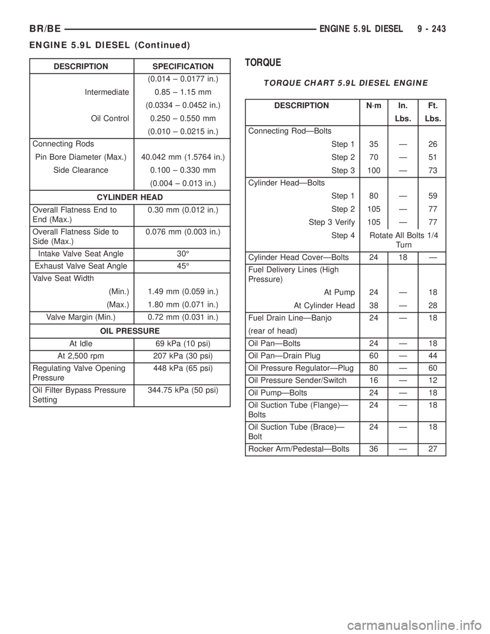
DESCRIPTION SPECIFICATION
(0.014 ± 0.0177 in.)
Intermediate 0.85 ± 1.15 mm
(0.0334 ± 0.0452 in.)
Oil Control 0.250 ± 0.550 mm
(0.010 ± 0.0215 in.)
Connecting Rods
Pin Bore Diameter (Max.) 40.042 mm (1.5764 in.)
Side Clearance 0.100 ± 0.330 mm
(0.004 ± 0.013 in.)
CYLINDER HEAD
Overall Flatness End to
End (Max.)0.30 mm (0.012 in.)
Overall Flatness Side to
Side (Max.)0.076 mm (0.003 in.)
Intake Valve Seat Angle 30É
Exhaust Valve Seat Angle 45É
Valve Seat Width
(Min.) 1.49 mm (0.059 in.)
(Max.) 1.80 mm (0.071 in.)
Valve Margin (Min.) 0.72 mm (0.031 in.)
OIL PRESSURE
At Idle 69 kPa (10 psi)
At 2,500 rpm 207 kPa (30 psi)
Regulating Valve Opening
Pressure448 kPa (65 psi)
Oil Filter Bypass Pressure
Setting344.75 kPa (50 psi)TORQUE
TORQUE CHART 5.9L DIESEL ENGINE
DESCRIPTION N´m In. Ft.
Lbs. Lbs.
Connecting RodÐBolts
Step 1 35 Ð 26
Step 2 70 Ð 51
Step 3 100 Ð 73
Cylinder HeadÐBolts
Step 1 80 Ð 59
Step 2 105 Ð 77
Step 3 Verify 105 Ð 77
Step 4 Rotate All Bolts 1/4
Turn
Cylinder Head CoverÐBolts 24 18 Ð
Fuel Delivery Lines (High
Pressure)
At Pump 24 Ð 18
At Cylinder Head 38 Ð 28
Fuel Drain LineÐBanjo 24 Ð 18
(rear of head)
Oil PanÐBolts 24 Ð 18
Oil PanÐDrain Plug 60 Ð 44
Oil Pressure RegulatorÐPlug 80 Ð 60
Oil Pressure Sender/Switch 16 Ð 12
Oil PumpÐBolts 24 Ð 18
Oil Suction Tube (Flange)Ð
Bolts24 Ð 18
Oil Suction Tube (Brace)Ð
Bolt24 Ð 18
Rocker Arm/PedestalÐBolts 36 Ð 27
BR/BEENGINE 5.9L DIESEL 9 - 243
ENGINE 5.9L DIESEL (Continued)
Page 1393 of 2889
CYLINDER HEAD
DESCRIPTION
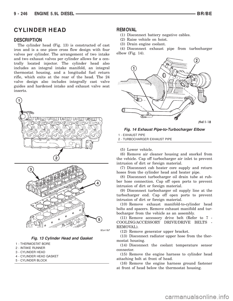
The cylinder head (Fig. 13) is constructed of cast
iron and is a one piece cross flow design with four
valves per cylinder. The arrangement of two intake
and two exhaust valves per cylinder allows for a cen-
trally located injector. The cylinder head also
includes an integral intake manifold, an integral
thermostat housing, and a longitudal fuel return
rifle, which exits at the rear of the head. The 24
valve design also includes integrally cast valve
guides and hardened intake and exhaust valve seat
inserts.
REMOVAL
(1) Disconnect battery negative cables.
(2) Raise vehicle on hoist.
(3) Drain engine coolant.
(4) Disconnect exhaust pipe from turbocharger
elbow (Fig. 14).
(5) Lower vehicle.
(6) Remove air cleaner housing and snorkel from
the vehicle. Cap off turbocharger air inlet to prevent
intrusion of dirt or foreign material.
(7) Disconnect cab heater core supply and return
hoses from the cylinder head and heater pipe.
(8) Disconnect turbocharger oil drain tube at rub-
ber hose connection. Cap off open ports to prevent
intrusion of dirt or foreign material.
(9) Disconnect turbocharger oil supply line at the
turbocharger end. Cap off open ports to prevent
intrusion of dirt or foreign material.
(10) Remove exhaust manifold-to-cylinder head
bolts and spacers. Remove exhaust manifold and tur-
bocharger from the vehicle as an assembly.
(11) Remove accessory drive belt (Refer to 7 -
COOLING/ACCESSORY DRIVE/DRIVE BELTS -
REMOVAL).
(12) Remove generator upper bracket.
(13) Disconnect radiator upper hose from the ther-
mostat housing.
(14) Disconnect the coolant temperature sensor
connector.
(15) Remove the engine harness to cylinder head
attaching bolt at front of head.
(16) Remove the engine harness ground fastener
at front of head below the thermostat housing.
Fig. 13 Cylinder Head and Gasket
1 - THERMOSTAT BORE
2 - INTAKE RUNNER
3 - CYLINDER HEAD
4 - CYLINDER HEAD GASKET
5 - CYLINDER BLOCK
Fig. 14 Exhaust Pipe-to-Turbocharger Elbow
1 - EXHAUST PIPE
2 - TURBOCHARGER EXHAUST PIPE
9 - 246 ENGINE 5.9L DIESELBR/BE
Page 1396 of 2889
After rinsing, use compressed air to dry the cylin-
der head.
Polish the gasket surface with 400 grit paper. Use
an orbital sander or sanding block to maintain a flat
surface.
CLEANINGÐCROSSHEADS
Clean all crossheads in a suitable solvent. If neces-
sary, use a wire brush or wheel to remove stubborn
deposits. Rinse in hot water and blow dry with com-
pressed air.
CLEANINGÐPUSHRODS
Clean the pushrods in a suitable solvent. Rinse in
hot water and blow dry with compressed air. If nec-
essary, use a wire brush or wheel to remove stubborn
deposits.
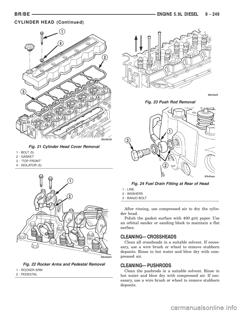
Fig. 21 Cylinder Head Cover Removal
1 - BOLT (5)
2 - GASKET
3 - ªTOP FRONTº
4 - ISOLATOR (5)
Fig. 22 Rocker Arms and Pedestal Removal
1 - ROCKER ARM
2 - PEDESTAL
Fig. 23 Push Rod Removal
Fig. 24 Fuel Drain Fitting at Rear of Head
1 - LINE
2 - WASHERS
3 - BANJO BOLT
BR/BEENGINE 5.9L DIESEL 9 - 249
CYLINDER HEAD (Continued)
Page 1399 of 2889
(e) Install the front line bundle (cyls. #1, 2, and
4) following the same procedure used for the rear
line bundle.
(f) Torque the connections at the cylinder head
first. Torque connections to 38 N´m (28 ft. lbs.).
(g) Torque the line connections at the injection
pump to 24 N´m (18 ft. lbs.).
(h) Install the injection line support bracket to
intake cover/cylinder head bolts and torque to 24
N´m (18 ft. lbs.).
(16) Install the engine lift bracket at the rear of
cylinder head. Torque to 77 N´m (57 ft. lbs.).
(17) Install the fuel filter to injection pump low
pressure line. Inspect and replace sealing washers if
necessary. Torque banjo bolts to 24 N´m (18 ft. lbs.).
(18) Using new gaskets, install the intake grid
heater and air inlet housing. Torque bolts to 24 N´m
(18 ft. lbs.).
(19) Connect the APPS connector (Fig. 17).
(20) Install the APPS assembly. to the cylinder
head bracket and torque bolts to 12 N´m (105 in.
lbs.).
(21) Install the throttle linkage cover (Fig. 15).
(22) Install the charge air cooler-to-air inlet hous-
ing duct assembly. Torque all clamps to 11 N´m (100
in. lbs.).
(23) Connect intake grid heater wires.
(24) Fasten engine harness to front of cylinder
head with bolt.
(25) Install engine harness ground wire and torque
bolt to 24 N´m (18 ft. lbs.).
(26) Connect engine coolant temperature sensor
connector.
(27) Connect radiator upper hose to thermostat
housing.
(28) Install generator upper bracket and torque
bolts to 41 N´m (31 ft. lbs.).
(29) Install accessory drive belt (Refer to 7 -
COOLING/ACCESSORY DRIVE/DRIVE BELTS -
INSTALLATION).
(30) Install exhaust manifold/turbocharger assem-
bly. and start all bolts/spacers by hand. Torque bolts
to 43 N´m (32 ft. lbs.).
(31) Connect turbocharger oil drain tube.
(32) Perform the turbocharger pre-lube procedure.
Refer to Group 11, Exhaust System and Turbo-
charger for the correct procedure.
(33) Connect the turbocharger oil supply line.
(34) Install air cleaner housing and duct.
(35) Raise vehicle on hoist.
(36) Install exhaust pipe to turbocharger elbow
(Fig. 14). Torque bolts to 34 N´m (25 ft. lbs.).
(37) Lower vehicle.
(38) Fill engine coolant (Refer to 7 - COOLING -
STANDARD PROCEDURE).
(39) Start engine and check for leaks.
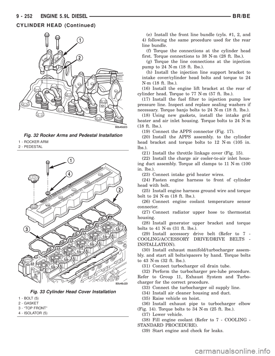
Fig. 32 Rocker Arms and Pedestal Installation
1 - ROCKER ARM
2 - PEDESTAL
Fig. 33 Cylinder Head Cover Installation
1 - BOLT (5)
2 - GASKET
3 - ªTOP FRONTº
4 - ISOLATOR (5)
9 - 252 ENGINE 5.9L DIESELBR/BE
CYLINDER HEAD (Continued)
Page 1423 of 2889
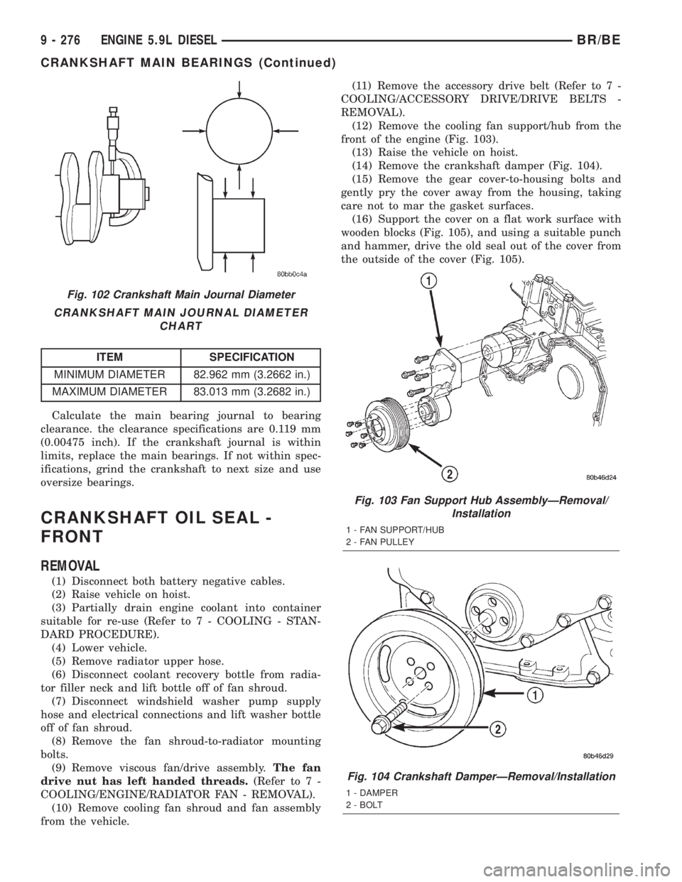
CRANKSHAFT MAIN JOURNAL DIAMETER
CHART
ITEM SPECIFICATION
MINIMUM DIAMETER 82.962 mm (3.2662 in.)
MAXIMUM DIAMETER 83.013 mm (3.2682 in.)
Calculate the main bearing journal to bearing
clearance. the clearance specifications are 0.119 mm
(0.00475 inch). If the crankshaft journal is within
limits, replace the main bearings. If not within spec-
ifications, grind the crankshaft to next size and use
oversize bearings.
CRANKSHAFT OIL SEAL -
FRONT
REMOVAL
(1) Disconnect both battery negative cables.
(2) Raise vehicle on hoist.
(3) Partially drain engine coolant into container
suitable for re-use (Refer to 7 - COOLING - STAN-
DARD PROCEDURE).
(4) Lower vehicle.
(5) Remove radiator upper hose.
(6) Disconnect coolant recovery bottle from radia-
tor filler neck and lift bottle off of fan shroud.
(7) Disconnect windshield washer pump supply
hose and electrical connections and lift washer bottle
off of fan shroud.
(8) Remove the fan shroud-to-radiator mounting
bolts.
(9) Remove viscous fan/drive assembly.The fan
drive nut has left handed threads.(Refer to 7 -
COOLING/ENGINE/RADIATOR FAN - REMOVAL).
(10) Remove cooling fan shroud and fan assembly
from the vehicle.(11) Remove the accessory drive belt (Refer to 7 -
COOLING/ACCESSORY DRIVE/DRIVE BELTS -
REMOVAL).
(12) Remove the cooling fan support/hub from the
front of the engine (Fig. 103).
(13) Raise the vehicle on hoist.
(14) Remove the crankshaft damper (Fig. 104).
(15) Remove the gear cover-to-housing bolts and
gently pry the cover away from the housing, taking
care not to mar the gasket surfaces.
(16) Support the cover on a flat work surface with
wooden blocks (Fig. 105), and using a suitable punch
and hammer, drive the old seal out of the cover from
the outside of the cover (Fig. 105).
Fig. 102 Crankshaft Main Journal Diameter
Fig. 103 Fan Support Hub AssemblyÐRemoval/
Installation
1 - FAN SUPPORT/HUB
2 - FAN PULLEY
Fig. 104 Crankshaft DamperÐRemoval/Installation
1 - DAMPER
2 - BOLT
9 - 276 ENGINE 5.9L DIESELBR/BE
CRANKSHAFT MAIN BEARINGS (Continued)
Page 1426 of 2889
(3) Remove the oil pan drain plug and drain the
engine oil. Re-install plug and torque to 60 N´m (44
ft. lbs.) torque.
(4) Remove transmission and transfer case (if
equipped) from vehicle.
(5) Remove flywheel or torque converter drive
plate.
(6) Disconnect starter cables from starter motor.
(7) Remove starter motor (Refer to 8 - ELECTRI-
CAL/STARTING/STARTER MOTOR - REMOVAL)
and transmission adapter plate assembly.
(8) Disconnect cables from starter motor.
(9) Remove the eight flywheel housing to block
bolts and remove housing and starter motor as an
assembly.
(10) Remove oil pan bolts, break the pan to block
seal, and lower pan slightly and remove oil suction
tube fasteners.
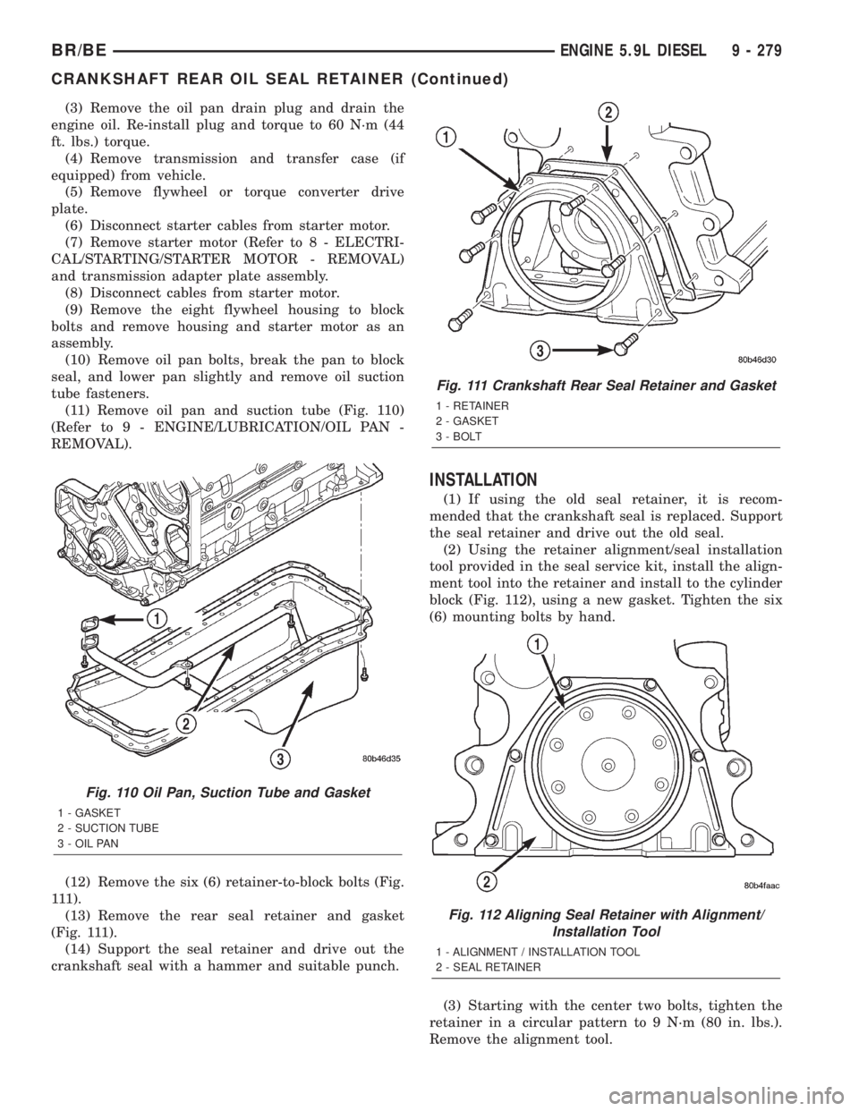
(11) Remove oil pan and suction tube (Fig. 110)
(Refer to 9 - ENGINE/LUBRICATION/OIL PAN -
REMOVAL).
(12) Remove the six (6) retainer-to-block bolts (Fig.
111).
(13) Remove the rear seal retainer and gasket
(Fig. 111).
(14) Support the seal retainer and drive out the
crankshaft seal with a hammer and suitable punch.
INSTALLATION
(1) If using the old seal retainer, it is recom-
mended that the crankshaft seal is replaced. Support
the seal retainer and drive out the old seal.
(2) Using the retainer alignment/seal installation
tool provided in the seal service kit, install the align-
ment tool into the retainer and install to the cylinder
block (Fig. 112), using a new gasket. Tighten the six
(6) mounting bolts by hand.
(3) Starting with the center two bolts, tighten the
retainer in a circular pattern to 9 N´m (80 in. lbs.).
Remove the alignment tool.
Fig. 110 Oil Pan, Suction Tube and Gasket
1 - GASKET
2 - SUCTION TUBE
3 - OIL PAN
Fig. 111 Crankshaft Rear Seal Retainer and Gasket
1 - RETAINER
2 - GASKET
3 - BOLT
Fig. 112 Aligning Seal Retainer with Alignment/
Installation Tool
1 - ALIGNMENT / INSTALLATION TOOL
2 - SEAL RETAINER
BR/BEENGINE 5.9L DIESEL 9 - 279
CRANKSHAFT REAR OIL SEAL RETAINER (Continued)
Page 1439 of 2889
LUBRICATION
DESCRIPTION
NOTE: Refer to (Fig. 148) and (Fig. 149) for circuit
illustrations.
A gear driven gerotor type oil pump is mounted
behind the front gear cover in the lower right portion
on the engine.
OPERATION
A gerotor style oil pump draws oil from the crank-
case through the suction tube and delivers it through
the block where it enters the oil cooler cover and
pressure regulator valve. When oil pressure exceeds
449 kPa (65 PSI), the valve opens exposing the dump
port, which routes excess oil back to the oil sump.
At the same time, oil is directed to a cast in pas-
sage in the oil cooler cover, leading to the oil cooler
element. As the oil travels through the element
plates, it is cooled by engine coolant traveling past
the outside of the plates. It is then routed to the oil
filter head and through a full flow oil filter. If a
plugged filter is encountered, the filter by-pass valve
opens, allowing unfiltered oil to lubricate the engine.
This condition can be avoided by frequent oil and fil-
ter changes, per the maintenance schedules found in
the owners manual. The by-pass valve is calibrated
to open when it sees a pressure drop of more than
344 kPa (50 psi) across the oil filter.The oil filter head then divides the oil between the
engine and the turbocharger. The turbocharger
receives filtered, cooled and pressurized oil through a
supply line from the filter head. The oil lubricates
the turbocharger and returns to the pan by way of a
drain tube connecting the bottom of the turbocharger
to a pressed in tube in the cylinder block.
Oil is then carried across the block to an angle
drilling which intersects the main oil rifle. The main
oil rifle runs the length of the block and delivers oil
to the crankshaft main journals and valve train. Oil
travels to the crankshaft through a series of transfer
drillings (one for each main bearing) and lubricates a
groove in the main bearing upper shell. From there
another drilling feeds the camshaft main journals.
The piston cooling nozzles are also supplied by the
main bearing upper shell. Crankshaft internal cross-
drillings supply oil to the connecting rod journals.
Another series of transfer drillings intersecting the
main oil rifle supply the valve train components. Oil
travels up the drilling, through a hole in the head
gasket, and through a drilling in the cylinder head
(one per cylinder), where it enters the rocker arm
pedestal and is divided between the intake and
exhaust rocker arm. Oil travels up and around the
rocker arm mounting bolt, and lubricates the rocker
shaft by cross drillings that intersect the mounting
bolt hole. Grooves at both ends of the rocker shaft
supply oil through the rocker arm where the oil trav-
els to the push rod and socket balls (Fig. 148) and
(Fig. 149).
9 - 292 ENGINE 5.9L DIESELBR/BE
Page 1443 of 2889
²Milky discoloration indicates coolant dilution.
(4) Clean the area around the oil filter head.
Remove the filter (Refer to 9 - ENGINE/LUBRICA-
TION/OIL FILTER - REMOVAL).
(5) Install new oil filter (Refer to 9 - ENGINE/LU-
BRICATION/OIL FILTER - INSTALLATION).
(6) Clean the drain plug and the sealing surface of
the pan. Check the condition of the threads and seal-
ing surface on the oil pan and drain plug.
(7) Install the drain plug. Tighten the plug to 60
N´m (44 ft. lbs.) torque.
(8) Use only High-Quality Multi-Viscosity lubricat-
ing oil in the Cummins Turbo Diesel engine. Choose
the correct oil for the operating conditions (Refer to
LUBRICATION & MAINTENANCE/FLUID TYPES -
DESCRIPTION).
(9) Fill the engine with the correct grade of new oil
(Refer to LUBRICATION & MAINTENANCE/FLUID
CAPACITIES - SPECIFICATIONS).
(10) Start the engine and operate it at idle for sev-
eral minutes. Check for leaks at the filter and drain
plug.
(11) Stop engine. Wait several minutes to allow the
oil to drain back to the pan and check the level
again.
USED ENGINE OIL DISPOSAL Care should be
exercised when disposing of used engine oil after
it has been drained from a vehicle's engine.
OIL COOLER & LINES
CLEANING AND INSPECTION
Clean the sealing surfaces.
Apply 483 kPa (70 psi) air pressure to the element
to check for leaks. If the element leaks, replace the
element.
OIL FILTER
REMOVAL
(1) Clean the area around the oil filter head.
Remove the filter using a 90-95 mm filter wrench.
(2) Clean the gasket surface of the filter head. The
filter canister O-Ring seal can stick on the filter
head. Make sure it is removed.
INSTALLATION
(1) Fill the oil filter element with clean oil before
installation. Use the same type oil that will be used
in the engine.
(2) Apply a light film of lubricating oil to the seal-
ing surface before installing the filter.CAUTION: Mechanical over-tightening may distort
the threads or damage the filter element seal.
(3) Install the filter until it contacts the sealing
surface of the oil filter adapter. Tighten filter an
additional ó turn.
OIL PAN
REMOVAL
(1) Disconnect the battery negative cables.
(2) Raise vehicle on hoist.
(3) Remove transmission and transfer case (if
equipped).
(4) Remove flywheel.
(5) Disconnect starter cables from starter motor.
(6) Remove starter motor (Refer to 8 - ELECTRI-
CAL/STARTING/STARTER MOTOR - REMOVAL)
and transmission adapter plate assembly.
WARNING: HOT OIL CAN CAUSE PERSONAL
INJURY.
(7) Drain the engine oil (Refer to 9 - ENGINE/LU-
BRICATION/OIL - STANDARD PROCEDURE).
(8) Install the oil pan drain plug with a new seal-
ing washer and tighten to 60 N´m (44 ft. lbs.) torque.
(9) Remove oil pan bolts, break the pan to block
seal, and lower pan slightly and remove oil suction
tube fasteners.
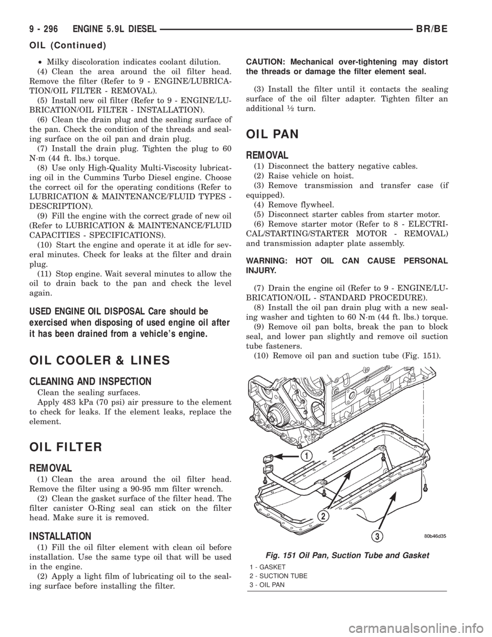
(10) Remove oil pan and suction tube (Fig. 151).
Fig. 151 Oil Pan, Suction Tube and Gasket
1 - GASKET
2 - SUCTION TUBE
3 - OIL PAN
9 - 296 ENGINE 5.9L DIESELBR/BE
OIL (Continued)