2001 DODGE RAM drain bolt
[x] Cancel search: drain boltPage 1444 of 2889
CLEANING
Remove all gasket material from the oil pan and
cylinder block sealing surfaces. Extra effort may be
required around T-joint areas. Clean oil pan and
flush suction tube with a suitable solvent.
INSPECTION
Inspect the oil pan, suction tube, and tube braces
for cracks and damage. Replace any defective compo-
nent. Inspect the oil drain plug and drain hole
threads. Inspect the oil pan sealing surface for
straightness. Repair any minor imperfections with a
ball-peen hammer. Do not attempt to repair an oil
pan by welding.
INSTALLATION
(1) Fill the T-joint between the pan rail/gear hous-
ing and pan rail/rear seal retainer with sealant. Use
MopartSilicone Rubber Adhesive Sealant or equiva-
lent.
(2) Place suction tube in oil pan and guide them
into place (Fig. 151). Using a new tube to oil pump
gasket, install and tighten the suction tube bolts by
hand. Starting with the oil pump inlet bolts, tighten
the bolts to 24 N´m (18 ft. lbs.) torque. Tighten the
remaining tube brace bolts to 24 N´m (18 ft. lbs.)
torque.
(3) Starting in the center and working outward,
tighten the oil pan bolts to 24 N´m (18 ft. lbs.)
torque.
(4) Install the flywheel housing assembly with the
starter motor attached and tighten bolts to 60 N´m
(44 ft. lbs.) torque.
(5) Connect starter motor cables.
(6) Install transmission and transfer case (if
equipped).
(7) Lower vehicle.
(8) Install battery negative cables.
(9) Fill the crankcase with new engine oil.
(10) Start engine and check for leaks. Stop engine,
check oil level, and adjust, if necessary.
OIL PRESSURE RELIEF VALVE
REMOVAL
(1) Disconnect the battery negative cables.
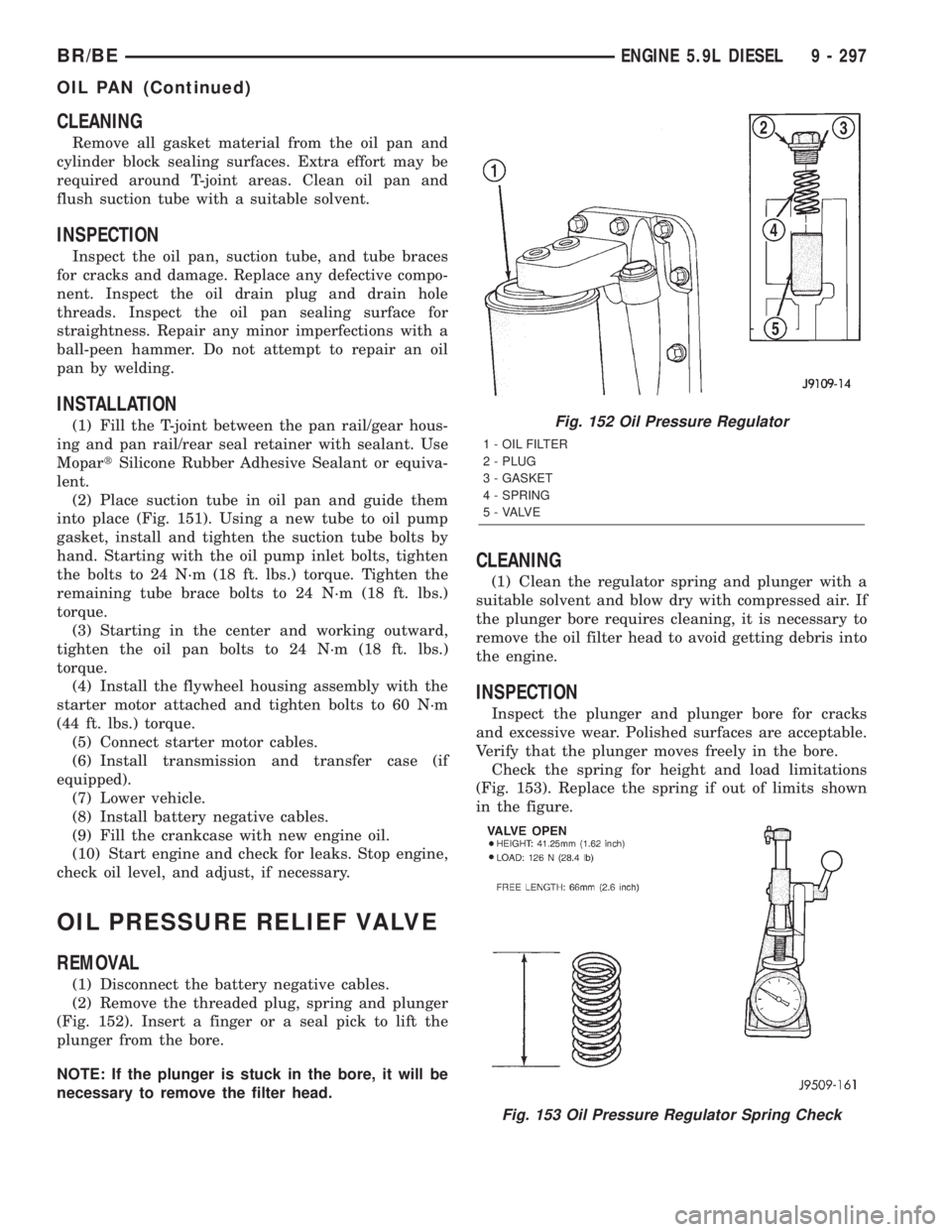
(2) Remove the threaded plug, spring and plunger
(Fig. 152). Insert a finger or a seal pick to lift the
plunger from the bore.
NOTE: If the plunger is stuck in the bore, it will be
necessary to remove the filter head.
CLEANING
(1) Clean the regulator spring and plunger with a
suitable solvent and blow dry with compressed air. If
the plunger bore requires cleaning, it is necessary to
remove the oil filter head to avoid getting debris into
the engine.
INSPECTION
Inspect the plunger and plunger bore for cracks
and excessive wear. Polished surfaces are acceptable.
Verify that the plunger moves freely in the bore.
Check the spring for height and load limitations
(Fig. 153). Replace the spring if out of limits shown
in the figure.
Fig. 152 Oil Pressure Regulator
1 - OIL FILTER
2 - PLUG
3 - GASKET
4 - SPRING
5 - VALVE
Fig. 153 Oil Pressure Regulator Spring Check
BR/BEENGINE 5.9L DIESEL 9 - 297
OIL PAN (Continued)
Page 1450 of 2889
(5) Using two (2) new gaskets, install the intake
air grid heater and air inlet housing (Fig. 168). Posi-
tion the ground cable and install and tighten the
bolts to 24 N´m (18 ft. lbs.) torque.
(6) Install and tighten the air intake heater power
supply nuts to 14 N´m (120 in. lbs.) torque.
(7) Install the engine oil dipstick tube and mount-
ing bolt (Fig. 167).
(8) Position the charge air cooler outlet tube onto
the air inlet housing (Fig. 167). Tighten the clamps
to 8 N´m (72 in. lbs.) torque.
(9) Perform the fuel system air bleed procedure
(Refer to 14 - FUEL SYSTEM/FUEL DELIVERY -
STANDARD PROCEDURE).
(10) Connect the battery negative cables.
EXHAUST MANIFOLD
REMOVAL
(1) Disconnect the battery negative cables.
(2) Raise vehicle on hoist.
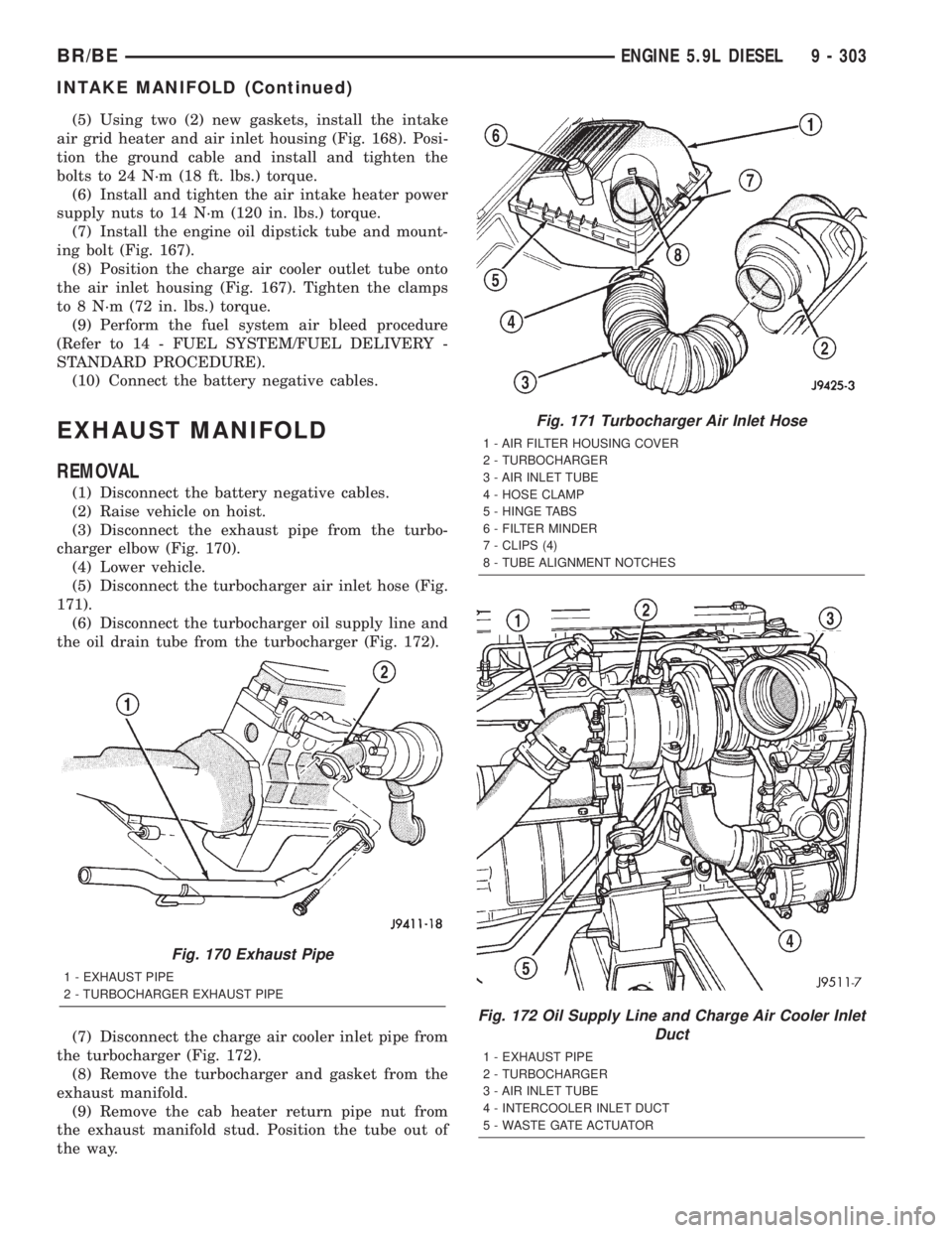
(3) Disconnect the exhaust pipe from the turbo-
charger elbow (Fig. 170).
(4) Lower vehicle.
(5) Disconnect the turbocharger air inlet hose (Fig.
171).
(6) Disconnect the turbocharger oil supply line and
the oil drain tube from the turbocharger (Fig. 172).
(7) Disconnect the charge air cooler inlet pipe from
the turbocharger (Fig. 172).
(8) Remove the turbocharger and gasket from the
exhaust manifold.
(9) Remove the cab heater return pipe nut from
the exhaust manifold stud. Position the tube out of
the way.
Fig. 170 Exhaust Pipe
1 - EXHAUST PIPE
2 - TURBOCHARGER EXHAUST PIPE
Fig. 171 Turbocharger Air Inlet Hose
1 - AIR FILTER HOUSING COVER
2 - TURBOCHARGER
3 - AIR INLET TUBE
4 - HOSE CLAMP
5 - HINGE TABS
6 - FILTER MINDER
7 - CLIPS (4)
8 - TUBE ALIGNMENT NOTCHES
Fig. 172 Oil Supply Line and Charge Air Cooler Inlet
Duct
1 - EXHAUST PIPE
2 - TURBOCHARGER
3 - AIR INLET TUBE
4 - INTERCOOLER INLET DUCT
5 - WASTE GATE ACTUATOR
BR/BEENGINE 5.9L DIESEL 9 - 303
INTAKE MANIFOLD (Continued)
Page 1451 of 2889
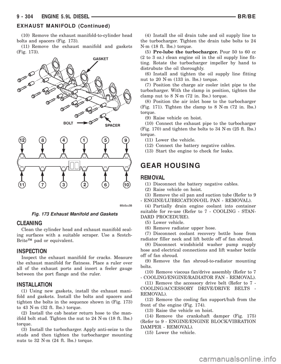
(10) Remove the exhaust manifold-to-cylinder head
bolts and spacers (Fig. 173).
(11) Remove the exhaust manifold and gaskets
(Fig. 173).
CLEANING
Clean the cylinder head and exhaust manifold seal-
ing surfaces with a suitable scraper. Use a Scotch-
BriteŸ pad or equivalent.
INSPECTION
Inspect the exhaust manifold for cracks. Measure
the exhaust manifold for flatness. Place a ruler over
all of the exhaust ports and insert a feeler gauge
between the port flange and the ruler.
INSTALLATION
(1) Using new gaskets, install the exhaust mani-
fold and gaskets. Install the bolts and spacers and
tighten the bolts in the sequence shown in (Fig. 173)
to 43 N´m (32 ft. lbs.) torque.
(2) Install the cab heater return hose to the man-
ifold bolt stud. Tighten the nut to 24 N´m (18 ft. lbs.)
torque.
(3) Install the turbocharger. Apply anti-seize to the
studs and then tighten the turbocharger mounting
nuts to 32 N´m (24 ft. lbs.) torque.(4) Install the oil drain tube and oil supply line to
the turbocharger. Tighten the drain tube bolts to 24
N´m (18 ft. lbs.) torque.
(5)Pre-lube the turbocharger.Pour 50 to 60 cc
(2 to 3 oz.) clean engine oil in the oil supply line fit-
ting. Rotate the turbocharger impeller by hand to
distrubute the oil thoroughly.
(6) Install and tighten the oil supply line fitting
nut to 20 N´m (133 in. lbs.) torque.
(7) Position the charge air cooler inlet pipe to the
turbocharger. With the clamp in position, tighten the
clamp nut to 8 N´m (72 in. lbs.) torque.
(8) Position the air inlet hose to the turbocharger
(Fig. 171). Tighten the clamp to 8 N´m (72 in. lbs.)
torque.
(9) Raise vehicle on hoist.
(10) Connect the exhaust pipe to the turbocharger
(Fig. 170) and tighten the bolts to 34 N´m (25 ft. lbs.)
torque.
(11) Lower the vehicle.
(12) Connect the battery negative cables.
(13) Start the engine to check for leaks.
GEAR HOUSING
REMOVAL
(1) Disconnect the battery negative cables.
(2) Raise vehicle on hoist.
(3) Remove the oil pan and suction tube (Refer to 9
- ENGINE/LUBRICATION/OIL PAN - REMOVAL).
(4) Partially drain engine coolant into container
suitable for re-use (Refer to 7 - COOLING - STAN-
DARD PROCEDURE).
(5) Lower vehicle.
(6) Remove radiator upper hose.
(7) Disconnect coolant recovery bottle hose from
radiator filler neck and lift bottle off of fan shroud.
(8) Disconnect windshield washer pump supply
hose and electrical connections and lift washer bottle
off of fan shroud.
(9) Remove the fan shroud-to-radiator mounting
bolts.
(10) Remove viscous fan/drive assembly (Refer to 7
- COOLING/ENGINE/RADIATOR FAN - REMOVAL).
(11) Remove the accessory drive belt (Refer to 7 -
COOLING/ACCESSORY DRIVE/DRIVE BELTS -
REMOVAL).
(12) Remove the cooling fan support/hub from the
front of the engine (Fig. 174).
(13) Raise the vehicle on hoist.
(14) Remove the crankshaft damper (Fig. 175)
(Refer to 9 - ENGINE/ENGINE BLOCK/VIBRATION
DAMPER - REMOVAL).
(15) Lower the vehicle.
Fig. 173 Exhaust Manifold and Gaskets
9 - 304 ENGINE 5.9L DIESELBR/BE
EXHAUST MANIFOLD (Continued)
Page 1453 of 2889
(3) Install the injection pump (Refer to 14 - FUEL
SYSTEM/FUEL DELIVERY/FUEL INJECTION
PUMP - INSTALLATION).
(4) Install the camshaft (Refer to 9 - ENGINE/EN-
GINE BLOCK/CAMSHAFT & BEARINGS (IN
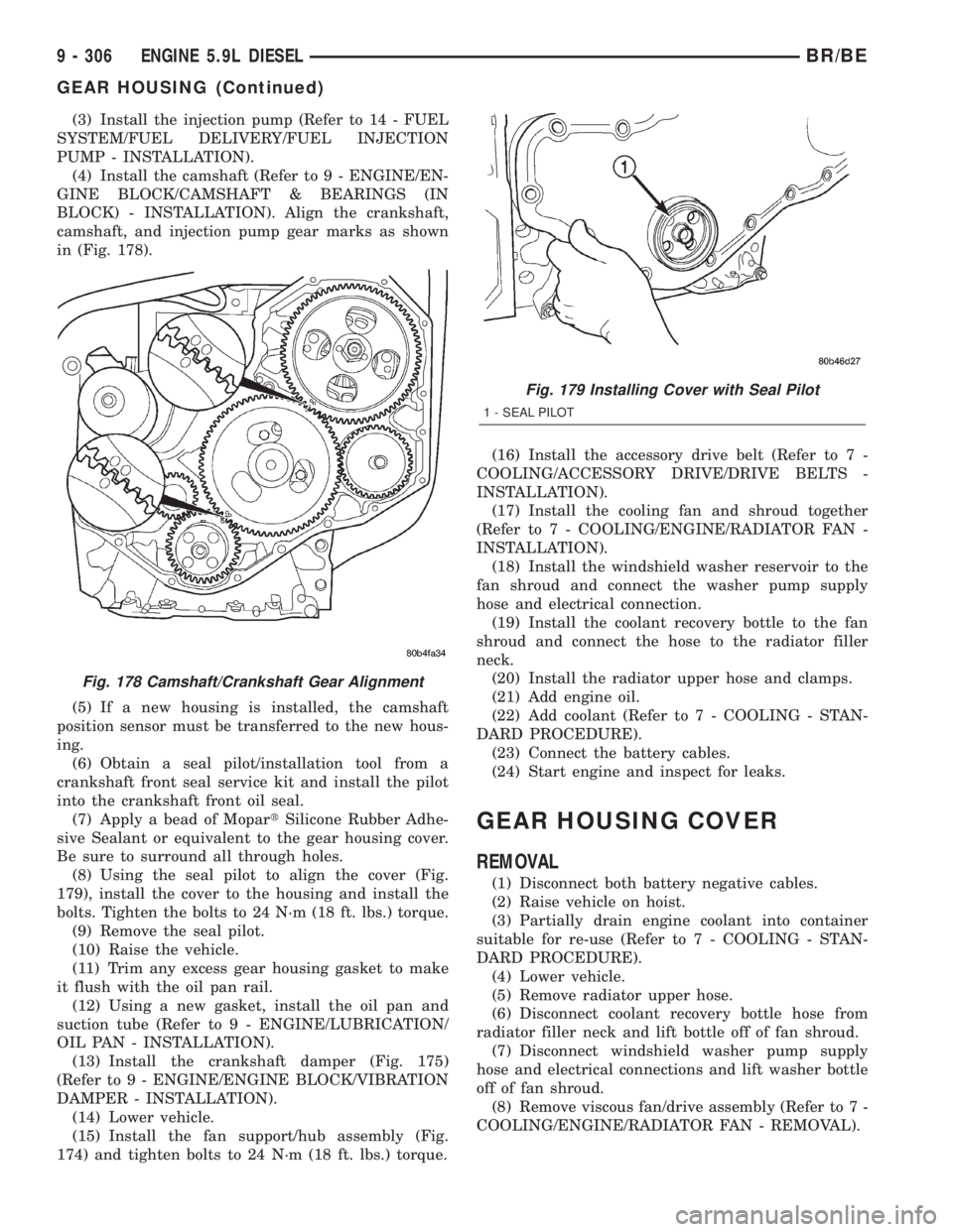
BLOCK) - INSTALLATION). Align the crankshaft,
camshaft, and injection pump gear marks as shown
in (Fig. 178).
(5) If a new housing is installed, the camshaft
position sensor must be transferred to the new hous-
ing.
(6) Obtain a seal pilot/installation tool from a
crankshaft front seal service kit and install the pilot
into the crankshaft front oil seal.
(7) Apply a bead of MopartSilicone Rubber Adhe-
sive Sealant or equivalent to the gear housing cover.
Be sure to surround all through holes.
(8) Using the seal pilot to align the cover (Fig.
179), install the cover to the housing and install the
bolts. Tighten the bolts to 24 N´m (18 ft. lbs.) torque.
(9) Remove the seal pilot.
(10) Raise the vehicle.
(11) Trim any excess gear housing gasket to make
it flush with the oil pan rail.
(12) Using a new gasket, install the oil pan and
suction tube (Refer to 9 - ENGINE/LUBRICATION/
OIL PAN - INSTALLATION).
(13) Install the crankshaft damper (Fig. 175)
(Refer to 9 - ENGINE/ENGINE BLOCK/VIBRATION
DAMPER - INSTALLATION).
(14) Lower vehicle.
(15) Install the fan support/hub assembly (Fig.
174) and tighten bolts to 24 N´m (18 ft. lbs.) torque.(16) Install the accessory drive belt (Refer to 7 -
COOLING/ACCESSORY DRIVE/DRIVE BELTS -
INSTALLATION).
(17) Install the cooling fan and shroud together
(Refer to 7 - COOLING/ENGINE/RADIATOR FAN -
INSTALLATION).
(18) Install the windshield washer reservoir to the
fan shroud and connect the washer pump supply
hose and electrical connection.
(19) Install the coolant recovery bottle to the fan
shroud and connect the hose to the radiator filler
neck.
(20) Install the radiator upper hose and clamps.
(21) Add engine oil.
(22) Add coolant (Refer to 7 - COOLING - STAN-
DARD PROCEDURE).
(23) Connect the battery cables.
(24) Start engine and inspect for leaks.
GEAR HOUSING COVER
REMOVAL
(1) Disconnect both battery negative cables.
(2) Raise vehicle on hoist.
(3) Partially drain engine coolant into container
suitable for re-use (Refer to 7 - COOLING - STAN-
DARD PROCEDURE).
(4) Lower vehicle.
(5) Remove radiator upper hose.
(6) Disconnect coolant recovery bottle hose from
radiator filler neck and lift bottle off of fan shroud.
(7) Disconnect windshield washer pump supply
hose and electrical connections and lift washer bottle
off of fan shroud.
(8) Remove viscous fan/drive assembly (Refer to 7 -
COOLING/ENGINE/RADIATOR FAN - REMOVAL).
Fig. 178 Camshaft/Crankshaft Gear Alignment
Fig. 179 Installing Cover with Seal Pilot
1 - SEAL PILOT
9 - 306 ENGINE 5.9L DIESELBR/BE
GEAR HOUSING (Continued)
Page 1460 of 2889
SPECIFICATIONS
TORQUE
DESCRIPTION N´m Ft. In.
Lbs. Lbs.
Adjusting StrapÐBolt 23 Ð 200
Air Heater Power SupplyÐ
Nuts14 Ð 124
Air Inlet HousingÐBolts 24 18 Ð
Cab Heater Supply/Return
LineÐNuts24 18 Ð
Exhaust ClampÐNuts 48 35 Ð
Exhaust Manifold to Cylinder
HeadÐBolts
(Diesel Engine) 43 32 Ð
Exhaust Manifold to Cylinder
HeadÐBolts
(3.9L/5.2L/5.9L) 31 23 Ð
Exhaust Manifold to Cylinder
HeadÐBolts
(8.0L) 22 Ð 195
Exhaust Pipe to ManifoldÐ
Bolts31 23 Ð
Generator MountingÐBolts 41 30 Ð
Charge Air Cooler
MountingÐBolts2Ð17
Charge Air Cooler DuctÐ
Nuts8Ð72
Heat ShieldÐNuts and Bolts 11 Ð 100
Turbocharger MountingÐ
Nuts32 24 Ð
Turbocharger Oil Drain
TubeÐBolts24 18 Ð
Turbocharger Oil Supply
LineÐFitting15 Ð 133
Turbocharger V-Band
ClampÐNut9Ð75
CATALYTIC CONVERTER -
3.9L/5.2L/5.9L
DESCRIPTION
The stainless steel catalytic converter is located
under the vehicle, integral to the exhaust pipe(s).
OPERATION
The catalytic converter captures and burns any
unburned fuel mixture exiting the combustion cham-
bers during the exhaust stroke of the engine. This
process aids in reducing emissions output.
REMOVAL
(1) Raise and support vehicle.
(2) Saturate the bolts and nuts with heat valve
lubricant. Allow 5 minutes for penetration.
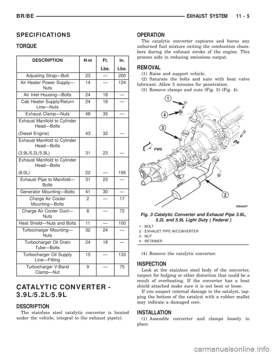
(3) Remove clamps and nuts (Fig. 3) (Fig. 4).
(4) Remove the catalytic converter.
INSPECTION
Look at the stainless steel body of the converter,
inspect for bulging or other distortion that could be a
result of overheating. If the converter has a heat
shield attached make sure it is not bent or loose.
If you suspect internal damage to the catalyst, tap-
ping the bottom of the catalyst with a rubber mallet
may indicate a damaged core.
INSTALLATION
(1) Assemble converter and clamps loosely in
place.
Fig. 3 Catalytic Converter and Exhaust Pipe 3.9L,
5.2L and 5.9L Light Duty ( Federal )
1 - BOLT
2 - EXHAUST PIPE W/CONVERTER
3 - NUT
4 - RETAINER
BR/BEEXHAUST SYSTEM 11 - 5
Page 1471 of 2889
CAUTION: The turbocharger is only serviced as an
assembly. Do not attempt to repair the turbocharger
as turbocharger and/or engine damage can result.
CLEANING
Clean the turbocharger and exhaust manifold
mounting surfaces with a suitable scraper.
INSPECTION
Visually inspect the turbocharger and exhaust
manifold gasket surfaces. Replace stripped or eroded
mounting studs.
(1) Visually inspect the turbocharger for cracks.
The following cracks are NOT acceptable:
²Cracks in the turbine and compressor housing
that go completely through.
²Cracks in the mounting flange that are longer
than 15 mm (0.6 in.).
²Cracks in the mounting flange that intersect
bolt through-holes.
²Two (2) Cracks in the mounting flange that are
closer than 6.4 mm (0.25 in.) together.
(2) Visually inspect the impeller and compressor
wheel fins for nicks, cracks, or chips. Note: Some
impellers may have a factory placed paint mark
which, after normal operation, appears to be a crack.Remove this mark with a suitable solvent to verify
that it is not a crack.
(3) Visually inspect the turbocharger compressor
housing for an impeller rubbing condition (Fig. 25).
Replace the turbocharger if the condition exists.
(4) Measure the turbocharger axial end play:
(a) Install a dial indicator as shown in (Fig. 26).
Zero the indicator at one end of travel.
(b) Move the impeller shaft fore and aft and
record the measurement. Allowable end play is
0.038 mm (0.0015 in.) MIN. and 0.089 mm (0.0035
in.) MAX. If the recorded measurement falls out-
side these parameters, replace the turbocharger
assembly.
(5) Measure the turbocharger bearing radial clear-
ance:
(a) Insert a narrow blade or wire style feeler
gauge between the compressor wheel and the hous-
ing (Fig. 27).
(b) Gently push the compresser wheel toward
the housing and record the clearance.
(c) With the feeler gauge in the same location,
gently push the compressor wheel away from the
housing and again record the clearance.
(d) Subtract the smaller clearance from the
larger clearance. This is the radial bearing clear-
ance.
(e) Allowable radial bearing clearance is 0.326
mm (0.0128 in.) MIN. and 0.496 mm (0.0195 in.)
MAX. If the recorded measurement falls outside
these specifications, replace the turbocharger assy.
INSTALLATION
(1) Install the turbocharger. Apply anti-seize to the
studs and then tighten the turbocharger mounting
nuts to 32 N´m (24 ft. lbs.) torque.
(2) Install the oil drain tube and oil supply line to
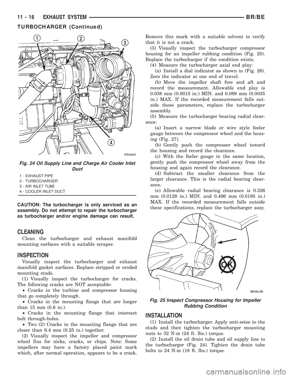
the turbocharger (Fig. 24). Tighten the drain tube
bolts to 24 N´m (18 ft. lbs.) torque.
Fig. 24 Oil Supply Line and Charge Air Cooler Inlet
Duct
1 - EXHAUST PIPE
2 - TURBOCHARGER
3 - AIR INLET TUBE
4 - COOLER INLET DUCT
Fig. 25 Inspect Compressor Housing for Impeller
Rubbing Condition
11 - 16 EXHAUST SYSTEMBR/BE
TURBOCHARGER (Continued)
Page 1506 of 2889
INSTALLATION - 8.0L
(1) Apply a small amount of engine oil to each fuel
injector o-ring. This will help in fuel rail installation.
(2) Install injector(s) and injector clip(s) to fuel
rail.
NOTE: The fuel injector electrical connectors on all
10 injectors should be facing to the right (passen-
ger) side of the vehicle (Fig. 34).
(3) Position the fuel rail/fuel injector assembly to
the injector openings on the intake manifold.
(4) Guide each injector into the intake manifold.
Be careful not to tear the injector o-ring.
(5) Push therightfuel rail down until fuel injec-
tors have bottomed on injector shoulder. Push the
leftfuel rail down until fuel injectors have bottomed
on injector shoulder.
(6) Install the six fuel rail mounting bolts into the
lower half of intake manifold. Tighten bolts to 15
N´m (136 in. lbs.) torque.
(7) Connect electrical connectors at all fuel injec-
tors. To install connector, refer to (Fig. 33). Push con-
nector onto injector (1) and then push and lock red
colored slider (2). Verify connector is locked to injec-
tor by lightly tugging on connector. The injector wir-
ing harness is numerically tagged.
(8) Install upper half of intake manifold. Refer to
Engines for procedures.
(9) Connect main fuel line at fuel rail. Refer to
Quick-Connect Fittings for procedures.
(10) Install ignition coil pack and bracket assem-
bly at intake manifold and right engine valve cover
(four bolts).
(11) Install throttle body to intake manifold. Refer
to Throttle Body removal in this group.
(12) Install throttle body linkage to throttle body.
(13) Install air cleaner tube and housing.
(14) Install negative battery cable at battery.
(15) Start engine and check for leaks.
FUEL TANK
DESCRIPTION
The fuel tank is constructed of a plastic material.
Its main functions are for fuel storage and for place-
ment of the fuel pump module.
OPERATION
All models pass a full 360 degree rollover test
without fuel leakage. To accomplish this, fuel and
vapor flow controls are required for all fuel tank con-
nections.A rollover valve(s) is mounted into the top of the
fuel tank (or pump module). Refer to Emission Con-
trol System for rollover valve information.
An evaporation control system is connected to the
rollover valve(s) to reduce emissions of fuel vapors
into the atmosphere. When fuel evaporates from the
fuel tank, vapors pass through vent hoses or tubes to
a charcoal canister where they are temporarily held.
When the engine is running, the vapors are drawn
into the intake manifold. Certain models are also
equipped with a self-diagnosing system using a Leak
Detection Pump (LDP). Refer to Emission Control
System for additional information.
REMOVAL
WARNING: GASOLINE POWERED ENGINES: THE
FUEL SYSTEM IS UNDER A CONSTANT PRESSURE
EVEN WITH THE ENGINE OFF. BEFORE SERVICING
THE FUEL TANK, FUEL SYSTEM PRESSURE MUST
BE RELEASED. REFER TO THE FUEL SYSTEM
PRESSURE RELEASE PROCEDURE BEFORE SER-
VICING THE FUEL TANK.
Two different procedures may be used to drain fuel
tank (lowering tank or using DRB scan tool). When
equipped with a diesel engine, the DRB scan tool
cannot be used (no electric fuel pump).
The quickest draining procedure involves lowering
the fuel tank.
Gasoline Powered Engines:As an alternative
procedure, the electric fuel pump may be activated
allowing tank to be drained at fuel rail connection.
Refer to DRB scan tool for fuel pump activation pro-
cedures. Before disconnecting fuel line at fuel rail,
release fuel pressure. Refer to the Fuel System Pres-
sure Release Procedure in this group for procedures.
Attach end of special test hose tool number 6541,
6539, 6631 or 6923 at fuel rail disconnection (tool
number will depend on model and/or engine applica-
tion). Position opposite end of this hose tool to an
approved gasoline draining station. Activate fuel
pump and drain tank until empty.
If electric fuel pump is not operating, tank must be
lowered for fuel draining. Refer to following proce-
dures.
(1) Remove fuel tank filler tube cap.
(2) Perform Fuel System Pressure Release proce-
dure as described in this group.
(3) Gasoline Engines: Disconnect negative battery
cable at battery. Diesel Engines: Disconnect both neg-
ative battery cables at both batteries.
(4) Raise vehicle on hoist.
(5) Certain models are equipped with a separate
grounding wire (strap) connecting the fuel fill tube
assembly to the body. Disconnect wire by removing
screw.
BR/BEFUEL DELIVERY - GASOLINE 14 - 19
FUEL RAIL (Continued)
Page 1507 of 2889
(6)Open fuel fill door and remove screws mounting
fuel filler tube assembly to body. Do not disconnect
rubber fuel fill or vent hoses from tank at this time.
(7) Place a transmission jack under center of fuel
tank. Apply a slight amount of pressure to fuel tank
with transmission jack.
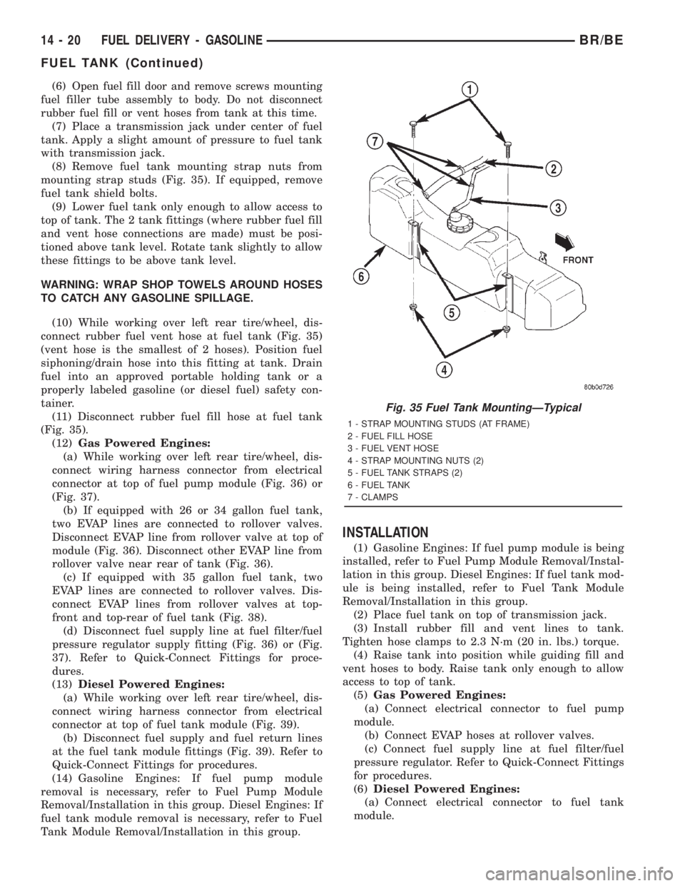
(8) Remove fuel tank mounting strap nuts from
mounting strap studs (Fig. 35). If equipped, remove
fuel tank shield bolts.
(9) Lower fuel tank only enough to allow access to
top of tank. The 2 tank fittings (where rubber fuel fill
and vent hose connections are made) must be posi-
tioned above tank level. Rotate tank slightly to allow
these fittings to be above tank level.
WARNING: WRAP SHOP TOWELS AROUND HOSES
TO CATCH ANY GASOLINE SPILLAGE.
(10) While working over left rear tire/wheel, dis-
connect rubber fuel vent hose at fuel tank (Fig. 35)
(vent hose is the smallest of 2 hoses). Position fuel
siphoning/drain hose into this fitting at tank. Drain
fuel into an approved portable holding tank or a
properly labeled gasoline (or diesel fuel) safety con-
tainer.
(11) Disconnect rubber fuel fill hose at fuel tank
(Fig. 35).
(12)Gas Powered Engines:
(a) While working over left rear tire/wheel, dis-
connect wiring harness connector from electrical
connector at top of fuel pump module (Fig. 36) or
(Fig. 37).
(b) If equipped with 26 or 34 gallon fuel tank,
two EVAP lines are connected to rollover valves.
Disconnect EVAP line from rollover valve at top of
module (Fig. 36). Disconnect other EVAP line from
rollover valve near rear of tank (Fig. 36).
(c) If equipped with 35 gallon fuel tank, two
EVAP lines are connected to rollover valves. Dis-
connect EVAP lines from rollover valves at top-
front and top-rear of fuel tank (Fig. 38).
(d) Disconnect fuel supply line at fuel filter/fuel
pressure regulator supply fitting (Fig. 36) or (Fig.
37). Refer to Quick-Connect Fittings for proce-
dures.
(13)Diesel Powered Engines:
(a) While working over left rear tire/wheel, dis-
connect wiring harness connector from electrical
connector at top of fuel tank module (Fig. 39).
(b) Disconnect fuel supply and fuel return lines
at the fuel tank module fittings (Fig. 39). Refer to
Quick-Connect Fittings for procedures.
(14) Gasoline Engines: If fuel pump module
removal is necessary, refer to Fuel Pump Module
Removal/Installation in this group. Diesel Engines: If
fuel tank module removal is necessary, refer to Fuel
Tank Module Removal/Installation in this group.
INSTALLATION
(1) Gasoline Engines: If fuel pump module is being
installed, refer to Fuel Pump Module Removal/Instal-
lation in this group. Diesel Engines: If fuel tank mod-
ule is being installed, refer to Fuel Tank Module
Removal/Installation in this group.
(2) Place fuel tank on top of transmission jack.
(3) Install rubber fill and vent lines to tank.
Tighten hose clamps to 2.3 N´m (20 in. lbs.) torque.
(4) Raise tank into position while guiding fill and
vent hoses to body. Raise tank only enough to allow
access to top of tank.
(5)Gas Powered Engines:
(a) Connect electrical connector to fuel pump
module.
(b) Connect EVAP hoses at rollover valves.
(c) Connect fuel supply line at fuel filter/fuel
pressure regulator. Refer to Quick-Connect Fittings
for procedures.
(6)Diesel Powered Engines:
(a) Connect electrical connector to fuel tank
module.
Fig. 35 Fuel Tank MountingÐTypical
1 - STRAP MOUNTING STUDS (AT FRAME)
2 - FUEL FILL HOSE
3 - FUEL VENT HOSE
4 - STRAP MOUNTING NUTS (2)
5 - FUEL TANK STRAPS (2)
6 - FUEL TANK
7 - CLAMPS
14 - 20 FUEL DELIVERY - GASOLINEBR/BE
FUEL TANK (Continued)