2001 DODGE RAM interior
[x] Cancel search: interiorPage 2652 of 2889
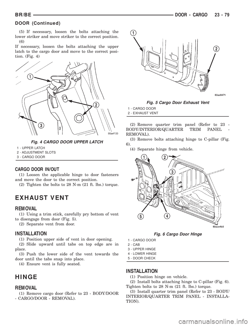
(5) If necessary, loosen the bolts attaching the
lower striker and move striker to the correct position.
(6)
If necessary, loosen the bolts attaching the upper
latch to the cargo door and move to the correct posi-
tion. (Fig. 4)
CARGO DOOR IN/OUT
(1) Loosen the applicable hinge to door fasteners
and move the door to the correct position.
(2) Tighten the bolts to 28 N´m (21 ft. lbs.) torque.
EXHAUST VENT
REMOVAL
(1) Using a trim stick, carefully pry bottom of vent
to disengage from door (Fig. 5).
(2) Separate vent from door.
INSTALLATION
(1) Position upper side of vent in door opening.
(2) Slide upward until tabs on top edge are in
place.
(3) Push the lower side of the vent towards the
door until the tabs snap into place.
(4) Ensure vent is fully seated.
HINGE
REMOVAL
(1) Remove cargo door (Refer to 23 - BODY/DOOR
- CARGO/DOOR - REMOVAL).(2) Remove quarter trim panel (Refer to 23 -
BODY/INTERIOR/QUARTER TRIM PANEL -
REMOVAL).
(3) Remove bolts attaching hinge to C-pillar (Fig.
6).
(4) Separate hinge from vehicle.
INSTALLATION
(1) Position hinge on vehicle.
(2) Install bolts attaching hinge to C-pillar (Fig. 6).
Tighten bolts to 28 N´m (21 ft. lbs.) torque.
(3) Install quarter trim panel (Refer to 23 - BODY/
INTERIOR/QUARTER TRIM PANEL - INSTALLA-
TION).
Fig. 4 CARGO DOOR UPPER LATCH
1 - UPPER LATCH
2 - ADJUSTMENT SLOTS
3 - CARGO DOOR
Fig. 5 Cargo Door Exhaust Vent
1 - CARGO DOOR
2 - EXHAUST VENT
Fig. 6 Cargo Door Hinge
1 - CARGO DOOR
2 - CAB
3 - UPPER HINGE
4 - LOWER HINGE
5 - DOOR CHECK
BR/BEDOOR - CARGO 23 - 79
DOOR (Continued)
Page 2679 of 2889
REMOVAL
WARNING: ON VEHICLES EQUIPPED WITH AIR-
BAGS, DISABLE THE AIRBAG SYSTEM BEFORE
ATTEMPTING ANY STEERING WHEEL, STEERING
COLUMN, OR INSTRUMENT PANEL COMPONENT
DIAGNOSIS OR SERVICE. DISCONNECT AND ISO-
LATE THE BATTERY NEGATIVE (GROUND) CABLE,
THEN WAIT TWO MINUTES FOR THE AIRBAG SYS-
TEM CAPACITOR TO DISCHARGE BEFORE PER-
FORMING FURTHER DIAGNOSIS OR SERVICE. THIS
IS THE ONLY SURE WAY TO DISABLE THE AIRBAG
SYSTEM. FAILURE TO TAKE THE PROPER PRE-
CAUTIONS COULD RESULT IN ACCIDENTAL AIR-
BAG DEPLOYMENT AND POSSIBLE PERSONAL
INJURY.
NOTE: Before starting this procedure, be certain to
turn the steering wheel until the front wheels are in
the straight-ahead position.
(1) Disconnect and isolate the battery negative
cable.
(2) Remove the Airbag Control Module (ACM) and
bracket from the floor panel transmission tunnel.
(Refer to 8 - ELECTRICAL/RESTRAINTS/AIRBAG
CONTROL MODULE - REMOVAL).
(3) Remove the trim from the left and right cowl
side inner panels. (Refer to 23 - BODY/INTERIOR/
COWL TRIM COVER - REMOVAL).
(4) Remove the steering column opening cover
from the instrument panel. (Refer to 23 - BODY/IN-
STRUMENT PANEL/STEERING COLUMN OPEN-
ING COVER - REMOVAL).
(5) Remove the two screws that secure the inside
hood latch release handle to the instrument panel
lower reinforcement and lower the release handle to
the floor.
(6) Disconnect the clockspring pigtail wire connec-
tor from the instrument panel wire harness connec-
tor located on the instrument panel lower
reinforcement.
(7) If the vehicle is so equipped, disconnect the
overdrive lockout switch pigtail wire connector from
the instrument panel wire harness connector near
the instrument panel lower reinforcement.
(8) Remove the steering column from the vehicle,
but do not remove the driver airbag, the steering
wheel, or the switches from the column. Be certain
that the steering wheel is locked and secured from
rotation to prevent the loss of clockspring centering.
(Refer to 19 - STEERING/COLUMN - REMOVAL).
(9) From under the driver side of the instrument
panel, perform the following:
(a) Disengage the park brake release handle
linkage rod from the park brake mechanism on theleft cowl side inner panel. (Refer to 5 - BRAKES/
PARKING BRAKE/RELEASE - REMOVAL).
(b) Disconnect the instrument panel wire har-
ness connector from the park brake switch on the
park brake mechanism.
(c) Disconnect the three connectors (one from the
body wire harness, and two from the headlamp and
dash wire harness) from the three connector recep-
tacles located closest to the dash panel on the back
of the Junction Block (JB).
(d) Remove the screw from the center of the
headlamp and dash wire harness to instrument
panel wire harness bulkhead connector and discon-
nect the connector.
(e) Disconnect the instrument panel wire har-
ness to door wire harness connector located directly
below the instrument panel wire harness to head-
lamp and dash wire harness bulkhead connector.
(f) If the vehicle is equipped with the Infinity
sound system option, disconnect the Infinity wire
harness connector from the instrument panel wire
harness connector that is secured to the outboard
side of the instrument panel wire harness to head-
lamp and dash wire harness bulkhead connector.
(g) Disconnect the instrument panel wire har-
ness connector from the stop lamp switch.
(h) Disconnect the heater-A/C housing vacuum
harness connector from the heater-A/C control vac-
uum harness connector located near the left end of
the heater-A/C housing.
(10) From under the passenger side of the instru-
ment panel, disconnect the two halves of the radio
antenna coaxial cable connector.
(11) Loosen the right and left instrument panel
cowl side roll-down bracket screws about 13 mm
(0.50 inch) (Fig. 1).
(12) Remove the five screws that secure the top of
the instrument panel to the top of the dash panel,
removing the center screw last.
(13) Roll down the instrument panel and install a
temporary hook in the center hole on top of the
instrument panel. Secure the other end of the hook
to the center hole in the top of the dash panel. The
hook should support the instrument panel in its
rolled down position about 46 cm (18 inches) from
the dash panel.
(14) With the instrument panel supported in the
roll-down position, disconnect the instrument panel
wire harness connectors from the heater-A/C housing
wire harness connectors.
(15) With the aid of an assistant, remove the tem-
porary hook and lift the instrument panel assembly
off of the roll-down bracket screws and remove it
from the vehicle.
23 - 106 INSTRUMENT PANEL SYSTEMBR/BE
INSTRUMENT PANEL SYSTEM (Continued)
Page 2681 of 2889
cowl side inner panel. (Refer to 5 - BRAKES/PARK-
ING BRAKE/RELEASE - INSTALLATION).
(b) Reconnect the instrument panel wire harness
connector to the park brake switch on the park
brake mechanism.
(c) Reconnect the three connectors (one from the
body wire harness, and two from the headlamp and
dash wire harness) to the three connector recepta-
cles located closest to the dash panel on the back of
the Junction Block (JB).
(d) Reconnect the headlamp and dash wire har-
ness to instrument panel wire harness bulkhead
connector and tighten the screw in the center of
the connector. Tighten the screw to 3.5 N´m (31 in.
lbs.).
(e) Reconnect the instrument panel wire harness
to door wire harness connector located directly
below the instrument panel wire harness to head-
lamp and dash wire harness bulkhead connector.
(f) If the vehicle is equipped with the Infinity
sound system option, reconnect the Infinity wire
harness connector to the instrument panel wire
harness connector that is secured to the outboard
side of the instrument panel wire harness to head-
lamp and dash wire harness bulkhead connector.
(g) Reconnect the instrument panel wire harness
connector to the stop lamp switch.
(h) Reconnect the heater-A/C housing vacuum
harness connector to the heater-A/C control vac-
uum harness connector located near the left end of
the heater-A/C housing.
(8) Reinstall the steering column into the vehicle.
Be certain that the steering wheel was locked and
secured from rotation to prevent the loss of clock-
spring centering. (Refer to 19 - STEERING/COL-
UMN - INSTALLATION).
(9) If the vehicle is so equipped, reconnect the
overdrive lockout switch pigtail wire connector to the
instrument panel wire harness connector near the
instrument panel lower reinforcement.
(10) Reconnect the clockspring pigtail wire connec-
tor to the instrument panel wire harness connector
at the instrument panel lower reinforcement.
(11) Position the inside hood latch release handle
to the instrument panel lower reinforcement.
(12) Install and tighten the two screws that secure
the inside hood latch release handle to the instru-
ment panel lower reinforcement. Tighten the screws
to 2.8 N´m (25 in. lbs.).
(13) Reinstall the steering column opening cover
onto the instrument panel. (Refer to 23 - BODY/IN-
STRUMENT PANEL/STEERING COLUMN OPEN-
ING COVER - INSTALLATION).
(14) Reinstall the trim onto the left and right cowl
side inner panels. (Refer to 23 - BODY/INTERIOR/
COWL TRIM COVER - INSTALLATION).(15) Reinstall the Airbag Control Module (ACM)
and bracket onto the floor panel transmission tunnel.
(Refer to 8 - ELECTRICAL/RESTRAINTS/AIRBAG
CONTROL MODULE - INSTALLATION).
(16) Reconnect the battery negative cable.
ASH RECEIVER
REMOVAL
WARNING: ON VEHICLES EQUIPPED WITH AIR-
BAGS, DISABLE THE AIRBAG SYSTEM BEFORE
ATTEMPTING ANY STEERING WHEEL, STEERING
COLUMN, OR INSTRUMENT PANEL COMPONENT
DIAGNOSIS OR SERVICE. DISCONNECT AND ISO-
LATE THE BATTERY NEGATIVE (GROUND) CABLE,
THEN WAIT TWO MINUTES FOR THE AIRBAG SYS-
TEM CAPACITOR TO DISCHARGE BEFORE PER-
FORMING FURTHER DIAGNOSIS OR SERVICE. THIS
IS THE ONLY SURE WAY TO DISABLE THE AIRBAG
SYSTEM. FAILURE TO TAKE THE PROPER PRE-
CAUTIONS COULD RESULT IN ACCIDENTAL AIR-
BAG DEPLOYMENT AND POSSIBLE PERSONAL
INJURY.
(1) Disconnect and isolate the battery negative
cable.
(2) Open the instrument panel ash receiver.
(3) From the open position, close the ash receiver
slightly and pull it straight back far enough to disen-
gage it from the pivot pins in the lower instrument
panel.
(4) Remove the three screws that secure the ash
receiver flame shield to the lower instrument panel
(Fig. 2).
(5) Pull the ash receiver flame shield out from the
instrument panel far enough to disengage the two
retaining tabs on the top of the shield from the
mounting holes in the instrument panel.
(6) Lower the flame shield from the instrument
panel far enough to access the ash receiver lamp and
hood.
(7) Squeeze the ash receiver lamp and hood
bracket to disengage the unit from the mounting hole
in the flame shield.
(8) Remove the ash receiver flame shield from the
instrument panel.
23 - 108 INSTRUMENT PANEL SYSTEMBR/BE
INSTRUMENT PANEL SYSTEM (Continued)
Page 2691 of 2889
INTERIOR
TABLE OF CONTENTS
page page
INTERIOR
CAUTION..............................118
A-PILLAR GRAB HANDLE
REMOVAL.............................119
INSTALLATION..........................119
A-PILLAR TRIM
REMOVAL.............................119
INSTALLATION..........................119
COWL TRIM COVER
REMOVAL.............................119
INSTALLATION..........................120
B-PILLAR TRIM
REMOVAL.............................120
INSTALLATION..........................120
REAR CLOSURE PANEL TRIM
REMOVAL.............................120
INSTALLATION..........................121
REAR FLOOR STOWAGE TRAY
REMOVAL.............................121
INSTALLATION..........................121
DOOR SILL TRIM
REMOVAL.............................121
INSTALLATION..........................121
SHIFT BOOT - MANUAL TRANSMISSION
REMOVAL.............................122
INSTALLATION..........................122
4WD FLOOR SHIFT BOOT
REMOVAL.............................122
INSTALLATION..........................122
CENTER CONSOLE
REMOVAL.............................122INSTALLATION..........................122
CARPETS AND FLOOR MATS
REMOVAL.............................123
INSTALLATION..........................123
ASSIST HANDLE
REMOVAL.............................124
INSTALLATION..........................124
COAT HOOK
REMOVAL.............................124
INSTALLATION..........................125
HEADLINER
REMOVAL.............................125
INSTALLATION..........................125
BODY VENT
REMOVAL.............................126
INSTALLATION..........................126
REAR VIEW MIRROR
REMOVAL.............................126
INSTALLATION..........................126
SUN VISOR
REMOVAL.............................127
INSTALLATION..........................127
QUARTER TRIM PANEL
REMOVAL.............................127
INSTALLATION..........................128
C-PILLAR TRIM
REMOVAL.............................128
INSTALLATION..........................128
INTERIOR
CAUTION
CAUTION: Do not attempt to remove interior trim
panels/moldings without first removing the neces-sary adjacent panels. To avoid damaging the pan-
els, ensure that all the screws and clips are
removed before attempting to remove an interior
trim panel/molding. Trim panels are somewhat flex-
ible but can be damaged if handled improperly.
23 - 118 INTERIORBR/BE
Page 2692 of 2889
A-PILLAR GRAB HANDLE
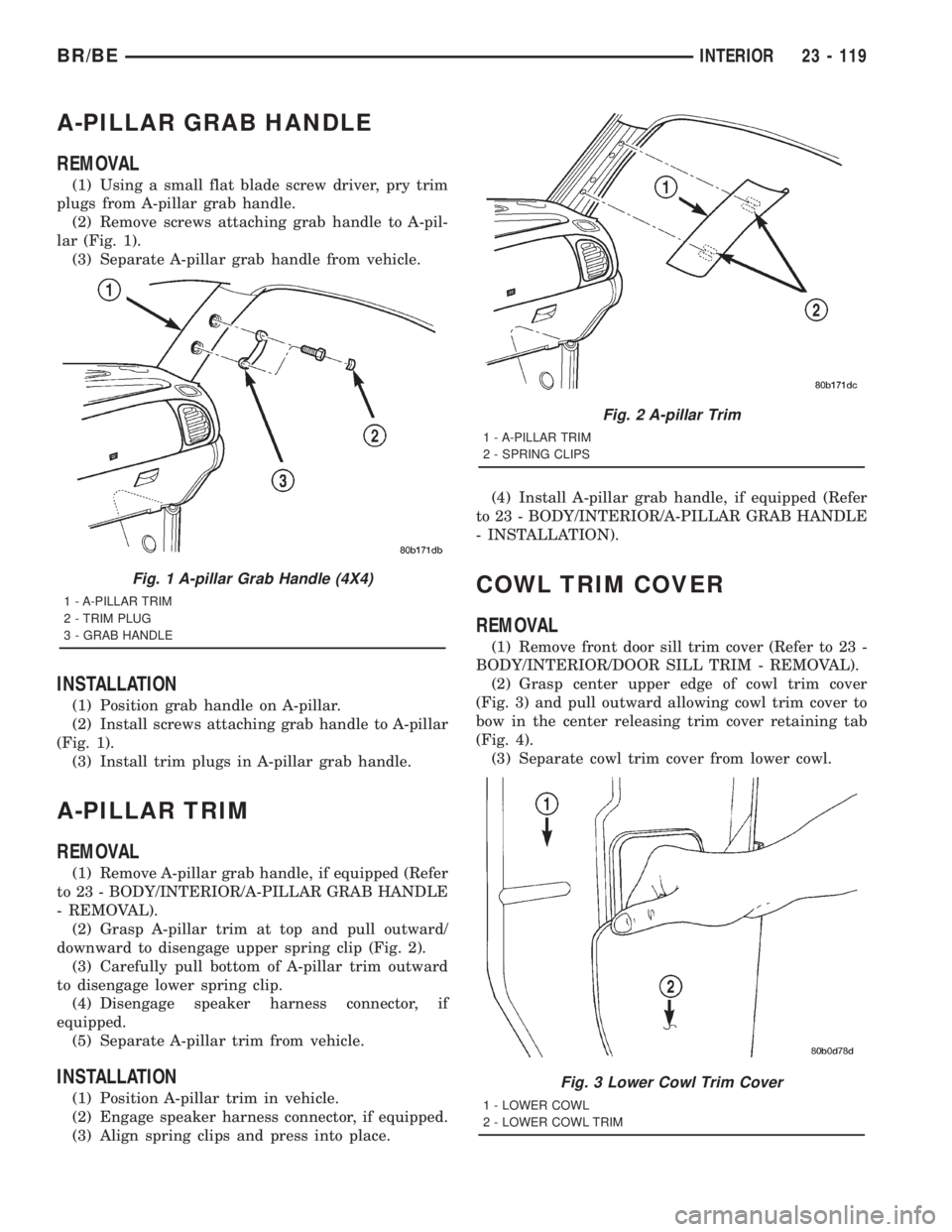
REMOVAL
(1) Using a small flat blade screw driver, pry trim
plugs from A-pillar grab handle.
(2) Remove screws attaching grab handle to A-pil-
lar (Fig. 1).
(3) Separate A-pillar grab handle from vehicle.
INSTALLATION
(1) Position grab handle on A-pillar.
(2) Install screws attaching grab handle to A-pillar
(Fig. 1).
(3) Install trim plugs in A-pillar grab handle.
A-PILLAR TRIM
REMOVAL
(1) Remove A-pillar grab handle, if equipped (Refer
to 23 - BODY/INTERIOR/A-PILLAR GRAB HANDLE
- REMOVAL).
(2) Grasp A-pillar trim at top and pull outward/
downward to disengage upper spring clip (Fig. 2).
(3) Carefully pull bottom of A-pillar trim outward
to disengage lower spring clip.
(4) Disengage speaker harness connector, if
equipped.
(5) Separate A-pillar trim from vehicle.
INSTALLATION
(1) Position A-pillar trim in vehicle.
(2) Engage speaker harness connector, if equipped.
(3) Align spring clips and press into place.(4) Install A-pillar grab handle, if equipped (Refer
to 23 - BODY/INTERIOR/A-PILLAR GRAB HANDLE
- INSTALLATION).
COWL TRIM COVER
REMOVAL
(1) Remove front door sill trim cover (Refer to 23 -
BODY/INTERIOR/DOOR SILL TRIM - REMOVAL).
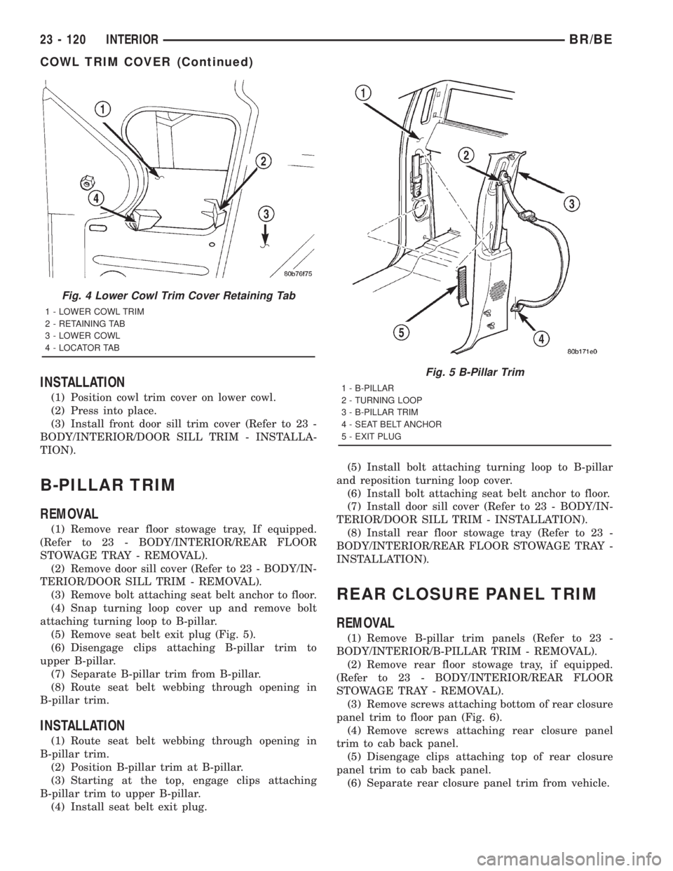
(2) Grasp center upper edge of cowl trim cover
(Fig. 3) and pull outward allowing cowl trim cover to
bow in the center releasing trim cover retaining tab
(Fig. 4).
(3) Separate cowl trim cover from lower cowl.
Fig. 1 A-pillar Grab Handle (4X4)
1 - A-PILLAR TRIM
2 - TRIM PLUG
3 - GRAB HANDLE
Fig. 2 A-pillar Trim
1 - A-PILLAR TRIM
2 - SPRING CLIPS
Fig. 3 Lower Cowl Trim Cover
1 - LOWER COWL
2 - LOWER COWL TRIM
BR/BEINTERIOR 23 - 119
Page 2693 of 2889
INSTALLATION
(1) Position cowl trim cover on lower cowl.
(2) Press into place.
(3) Install front door sill trim cover (Refer to 23 -
BODY/INTERIOR/DOOR SILL TRIM - INSTALLA-
TION).
B-PILLAR TRIM
REMOVAL
(1) Remove rear floor stowage tray, If equipped.
(Refer to 23 - BODY/INTERIOR/REAR FLOOR
STOWAGE TRAY - REMOVAL).
(2) Remove door sill cover (Refer to 23 - BODY/IN-
TERIOR/DOOR SILL TRIM - REMOVAL).
(3) Remove bolt attaching seat belt anchor to floor.
(4) Snap turning loop cover up and remove bolt
attaching turning loop to B-pillar.
(5) Remove seat belt exit plug (Fig. 5).
(6) Disengage clips attaching B-pillar trim to
upper B-pillar.
(7) Separate B-pillar trim from B-pillar.
(8) Route seat belt webbing through opening in
B-pillar trim.
INSTALLATION
(1) Route seat belt webbing through opening in
B-pillar trim.
(2) Position B-pillar trim at B-pillar.
(3) Starting at the top, engage clips attaching
B-pillar trim to upper B-pillar.
(4) Install seat belt exit plug.(5) Install bolt attaching turning loop to B-pillar
and reposition turning loop cover.
(6) Install bolt attaching seat belt anchor to floor.
(7) Install door sill cover (Refer to 23 - BODY/IN-
TERIOR/DOOR SILL TRIM - INSTALLATION).
(8) Install rear floor stowage tray (Refer to 23 -
BODY/INTERIOR/REAR FLOOR STOWAGE TRAY -
INSTALLATION).
REAR CLOSURE PANEL TRIM
REMOVAL
(1) Remove B-pillar trim panels (Refer to 23 -
BODY/INTERIOR/B-PILLAR TRIM - REMOVAL).
(2) Remove rear floor stowage tray, if equipped.
(Refer to 23 - BODY/INTERIOR/REAR FLOOR
STOWAGE TRAY - REMOVAL).
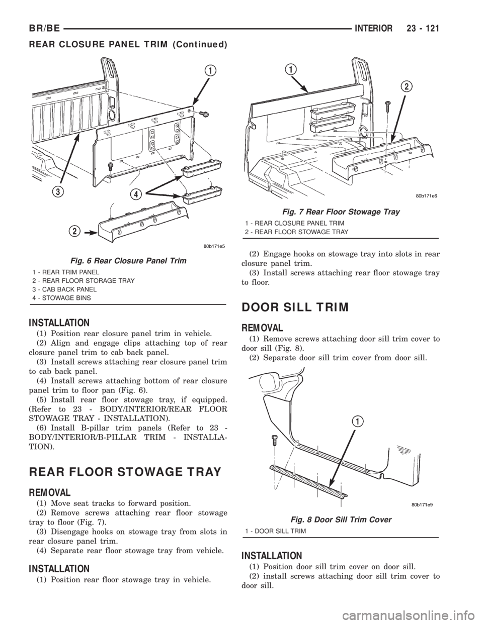
(3) Remove screws attaching bottom of rear closure
panel trim to floor pan (Fig. 6).
(4) Remove screws attaching rear closure panel
trim to cab back panel.
(5) Disengage clips attaching top of rear closure
panel trim to cab back panel.
(6) Separate rear closure panel trim from vehicle.
Fig. 4 Lower Cowl Trim Cover Retaining Tab
1 - LOWER COWL TRIM
2 - RETAINING TAB
3 - LOWER COWL
4 - LOCATOR TAB
Fig. 5 B-Pillar Trim
1 - B-PILLAR
2 - TURNING LOOP
3 - B-PILLAR TRIM
4 - SEAT BELT ANCHOR
5 - EXIT PLUG
23 - 120 INTERIORBR/BE
COWL TRIM COVER (Continued)
Page 2694 of 2889
INSTALLATION
(1) Position rear closure panel trim in vehicle.
(2) Align and engage clips attaching top of rear
closure panel trim to cab back panel.
(3) Install screws attaching rear closure panel trim
to cab back panel.
(4) Install screws attaching bottom of rear closure
panel trim to floor pan (Fig. 6).
(5) Install rear floor stowage tray, if equipped.
(Refer to 23 - BODY/INTERIOR/REAR FLOOR
STOWAGE TRAY - INSTALLATION).
(6) Install B-pillar trim panels (Refer to 23 -
BODY/INTERIOR/B-PILLAR TRIM - INSTALLA-
TION).
REAR FLOOR STOWAGE TRAY
REMOVAL
(1) Move seat tracks to forward position.
(2) Remove screws attaching rear floor stowage
tray to floor (Fig. 7).
(3) Disengage hooks on stowage tray from slots in
rear closure panel trim.
(4) Separate rear floor stowage tray from vehicle.
INSTALLATION
(1) Position rear floor stowage tray in vehicle.(2) Engage hooks on stowage tray into slots in rear
closure panel trim.
(3) Install screws attaching rear floor stowage tray
to floor.
DOOR SILL TRIM
REMOVAL
(1) Remove screws attaching door sill trim cover to
door sill (Fig. 8).
(2) Separate door sill trim cover from door sill.
INSTALLATION
(1) Position door sill trim cover on door sill.
(2) install screws attaching door sill trim cover to
door sill.
Fig. 6 Rear Closure Panel Trim
1 - REAR TRIM PANEL
2 - REAR FLOOR STORAGE TRAY
3 - CAB BACK PANEL
4 - STOWAGE BINS
Fig. 7 Rear Floor Stowage Tray
1 - REAR CLOSURE PANEL TRIM
2 - REAR FLOOR STOWAGE TRAY
Fig. 8 Door Sill Trim Cover
1 - DOOR SILL TRIM
BR/BEINTERIOR 23 - 121
REAR CLOSURE PANEL TRIM (Continued)
Page 2695 of 2889
SHIFT BOOT - MANUAL
TRANSMISSION
REMOVAL
(1) Using a trim stick, pry the corner of the shift
boot up expose the fasteners.
(2) Remove the screws attaching the shift boot to
the console.
(3) Remove the insert from the shift knob, remove
nut attaching knob to the lever, and remove the shift
knob.
(4) Lift floor shift boot off shifter.
INSTALLATION
(1) Install shift boot over the shift lever, position
boot on console and install the fasteners attaching
boot to concole.
(2) Install the shift knob, shift knob nut, and
tighten to 27.1 N´m (20 ft.lbs) torque.
(3) Install the shift knob insert.
4WD FLOOR SHIFT BOOT
REMOVAL
(1) Remove insert from shift knob.
(2) Remove nut attaching shift knob to shift lever.
(3) Remove shift knob.
(4) Using a trim stick, disengage retainers attach-
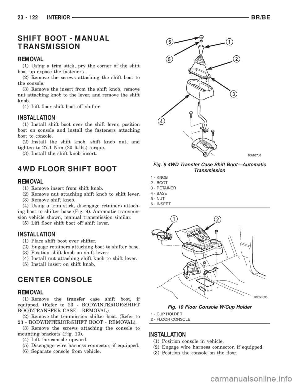
ing boot to shifter base (Fig. 9). Automatic transmis-
sion vehicle shown, manual transmission similar.
(5) Lift floor shift boot off shift lever.
INSTALLATION
(1) Place shift boot over shifter.
(2) Engage retainers attaching boot to shifter base.
(3) Position shift knob on shift lever.
(4) Install nut attaching shift knob to shift lever.
(5) Install insert on shift knob.
CENTER CONSOLE
REMOVAL
(1) Remove the transfer case shift boot, if
equipped. (Refer to 23 - BODY/INTERIOR/SHIFT
BOOT/TRANSFER CASE - REMOVAL).
(2) Remove the tranmission shifter boot. (Refer to
23 - BODY/INTERIOR/SHIFT BOOT - REMOVAL).
(3) Remove the screws attaching the console to
mounting brackets (Fig. 10).
(4) Lift the console upward.
(5) Disengage wire harness connector, if equipped.
(6) Separate console from vehicle.
INSTALLATION
(1) Position console in vehicle.
(2) Engage wire harness connector, if equipped.
(3) Position the console on the floor.
Fig. 9 4WD Transfer Case Shift BootÐAutomatic
Transmission
1 - KNOB
2 - BOOT
3 - RETAINER
4 - BASE
5 - NUT
6 - INSERT
Fig. 10 Floor Console W/Cup Holder
1 - CUP HOLDER
2 - FLOOR CONSOLE
23 - 122 INTERIORBR/BE