2001 DODGE RAM interior
[x] Cancel search: interiorPage 2829 of 2889
UNDER HOOD
INSPECTION - HOOD LATCH/SAFETY CATCH
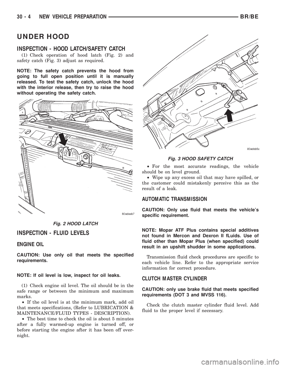
(1) Check operation of hood latch (Fig. 2) and
safety catch (Fig. 3) adjust as required.
NOTE: The safety catch prevents the hood from
going to full open position until it is manually
released. To test the safety catch, unlock the hood
with the interior release, then try to raise the hood
without operating the safety catch.
INSPECTION - FLUID LEVELS
ENGINE OIL
CAUTION: Use only oil that meets the specified
requirements.
NOTE: If oil level is low, inspect for oil leaks.
(1) Check engine oil level. The oil should be in the
safe range or between the minimum and maximum
marks.
²If the oil level is at the minimum mark, add oil
that meets specifications, (Refer to LUBRICATION &
MAINTENANCE/FLUID TYPES - DESCRIPTION).
²The best time to check the oil is about 5 minutes
after a fully warmed-up engine is turned off, or
before starting the engine after it has been off over-
night.²For the most accurate readings, the vehicle
should be on level ground.
²Wipe up any excess oil that may have spilled, or
the customer could mistakenly perceive this as the
result of a leak.
AUTOMATIC TRANSMISSION
CAUTION: Only use fluid that meets the vehicle's
specific requirement.
NOTE: Mopar ATF Plus contains special additives
not found in Mercon and Dexron II fLuids. Use of
fluid other than Mopar Plus (when specified) could
result in an upshift shudder in some applications.
Transmission fluid check procedures are specific to
each vehicle line. Refer to the appropriate service
information for correct procedure.
CLUTCH MASTER CYLINDER
CAUTION: only use brake fluid that meets specified
requirements (DOT 3 and MVSS 116).
Check the clutch master cylinder fluid level. Add
fluid to the proper level if necessary.
Fig. 2 HOOD LATCH
Fig. 3 HOOD SAFETY CATCH
30 - 4 NEW VEHICLE PREPARATIONBR/BE
Page 2832 of 2889
INSPECTION - BATTERY
When battery is easily accessible, check the test
indicator (green dot), terminal tightness and felt
(grease) washer on battery posts. Recharge battery as
required to assure that the green dot is visible.
When battery is not easily accessible check battery
condition with a voltmeter at the jump start loca-
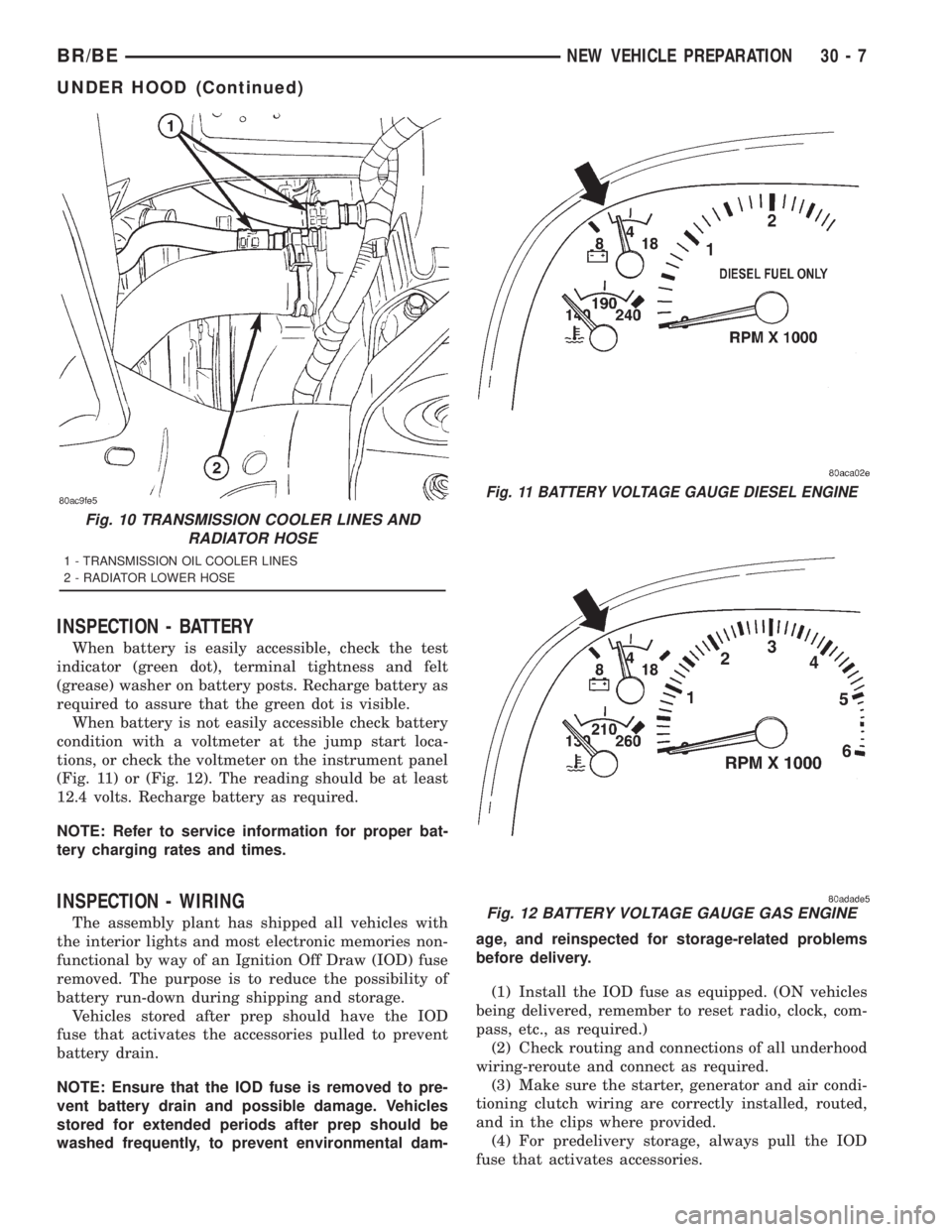
tions, or check the voltmeter on the instrument panel
(Fig. 11) or (Fig. 12). The reading should be at least
12.4 volts. Recharge battery as required.
NOTE: Refer to service information for proper bat-
tery charging rates and times.
INSPECTION - WIRING
The assembly plant has shipped all vehicles with
the interior lights and most electronic memories non-
functional by way of an Ignition Off Draw (IOD) fuse
removed. The purpose is to reduce the possibility of
battery run-down during shipping and storage.
Vehicles stored after prep should have the IOD
fuse that activates the accessories pulled to prevent
battery drain.
NOTE: Ensure that the IOD fuse is removed to pre-
vent battery drain and possible damage. Vehicles
stored for extended periods after prep should be
washed frequently, to prevent environmental dam-age, and reinspected for storage-related problems
before delivery.
(1) Install the IOD fuse as equipped. (ON vehicles
being delivered, remember to reset radio, clock, com-
pass, etc., as required.)
(2) Check routing and connections of all underhood
wiring-reroute and connect as required.
(3) Make sure the starter, generator and air condi-
tioning clutch wiring are correctly installed, routed,
and in the clips where provided.
(4) For predelivery storage, always pull the IOD
fuse that activates accessories.
Fig. 10 TRANSMISSION COOLER LINES AND
RADIATOR HOSE
1 - TRANSMISSION OIL COOLER LINES
2 - RADIATOR LOWER HOSE
Fig. 11 BATTERY VOLTAGE GAUGE DIESEL ENGINE
Fig. 12 BATTERY VOLTAGE GAUGE GAS ENGINE
BR/BENEW VEHICLE PREPARATION 30 - 7
UNDER HOOD (Continued)
Page 2837 of 2889
BODY INTERIOR
INSPECTION - COMPASS
NOTE: Set variance after calibration.
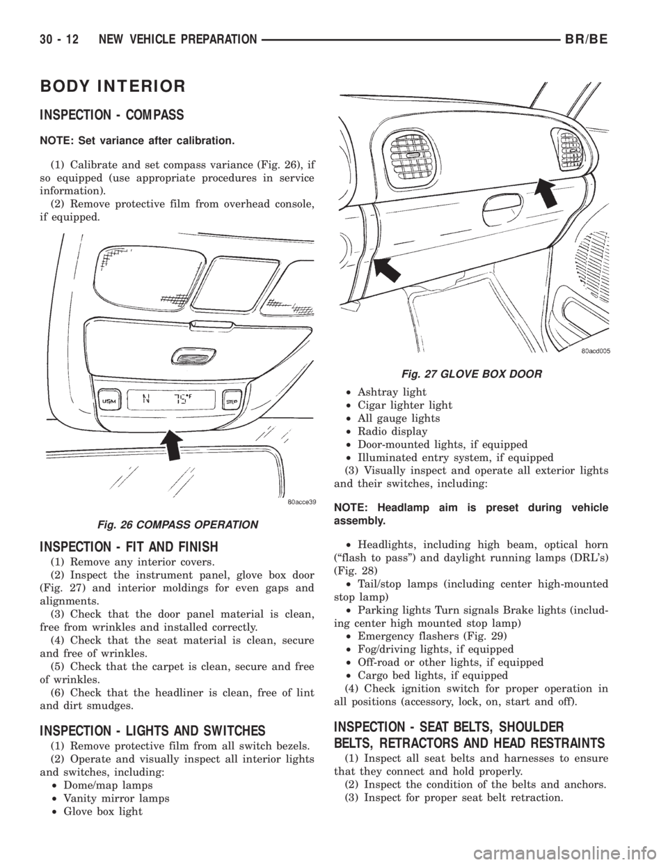
(1) Calibrate and set compass variance (Fig. 26), if
so equipped (use appropriate procedures in service
information).
(2) Remove protective film from overhead console,
if equipped.
INSPECTION - FIT AND FINISH
(1) Remove any interior covers.
(2) Inspect the instrument panel, glove box door
(Fig. 27) and interior moldings for even gaps and
alignments.
(3) Check that the door panel material is clean,
free from wrinkles and installed correctly.
(4) Check that the seat material is clean, secure
and free of wrinkles.
(5) Check that the carpet is clean, secure and free
of wrinkles.
(6) Check that the headliner is clean, free of lint
and dirt smudges.
INSPECTION - LIGHTS AND SWITCHES
(1) Remove protective film from all switch bezels.
(2) Operate and visually inspect all interior lights
and switches, including:
²Dome/map lamps
²Vanity mirror lamps
²Glove box light²Ashtray light
²Cigar lighter light
²All gauge lights
²Radio display
²Door-mounted lights, if equipped
²Illuminated entry system, if equipped
(3) Visually inspect and operate all exterior lights
and their switches, including:
NOTE: Headlamp aim is preset during vehicle
assembly.
²Headlights, including high beam, optical horn
(ªflash to passº) and daylight running lamps (DRL's)
(Fig. 28)
²Tail/stop lamps (including center high-mounted
stop lamp)
²Parking lights Turn signals Brake lights (includ-
ing center high mounted stop lamp)
²Emergency flashers (Fig. 29)
²Fog/driving lights, if equipped
²Off-road or other lights, if equipped
²Cargo bed lights, if equipped
(4) Check ignition switch for proper operation in
all positions (accessory, lock, on, start and off).
INSPECTION - SEAT BELTS, SHOULDER
BELTS, RETRACTORS AND HEAD RESTRAINTS
(1) Inspect all seat belts and harnesses to ensure
that they connect and hold properly.
(2) Inspect the condition of the belts and anchors.
(3) Inspect for proper seat belt retraction.
Fig. 26 COMPASS OPERATION
Fig. 27 GLOVE BOX DOOR
30 - 12 NEW VEHICLE PREPARATIONBR/BE
Page 2838 of 2889
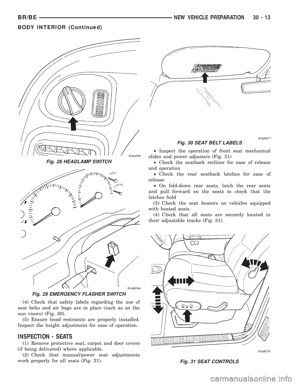
(4) Check that safety labels regarding the use of
seat belts and air bags are in place (such as on the
sun visors) (Fig. 30).
(5) Ensure head restraints are properly installed.
Inspect the height adjustment for ease of operation.
INSPECTION - SEATS
(1) Remove protective seat, carpet and door covers
(if being delivered) where applicable.
(2) Check that manual/power seat adjustments
work properly for all seats (Fig. 31).²Inspect the operation of front seat mechanical
slides and power adjusters (Fig. 31)
²Check the seatback recliner for ease of release
and operation
²Check the rear seatback latches for ease of
release
²On fold-down rear seats, latch the rear seats
and pull forward on the seats to check that the
latches hold
(3) Check the seat heaters on vehicles equipped
with heated seats.
(4) Check that all seats are securely located in
their adjustable tracks (Fig. 31).
Fig. 31 SEAT CONTROLS
Fig. 28 HEADLAMP SWITCH
Fig. 29 EMERGENCY FLASHER SWITCH
Fig. 30 SEAT BELT LABELS
BR/BENEW VEHICLE PREPARATION 30 - 13
BODY INTERIOR (Continued)
Page 2839 of 2889
INSPECTION - WINDOWS, DOORS AND LOCKS
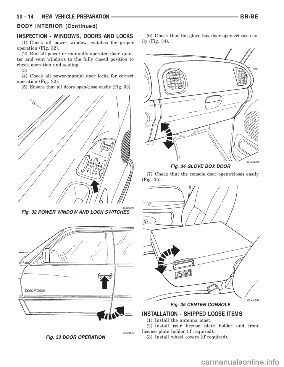
(1) Check all power window switches for proper
operation (Fig. 32).
(2) Run all power or manually operated door, quar-
ter and vent windows to the fully closed position to
check operation and sealing.
(3)
(4) Check all power/manual door locks for correct
operation (Fig. 32).
(5)
Ensure that all doors open/close easily (Fig. 33).
(6) Check that the glove box door opens/closes eas-
ily (Fig. 34).
(7) Check that the console door opens/closes easily
(Fig. 35).
INSTALLATION - SHIPPED LOOSE ITEMS
(1) Install the antenna mast.
(2) Install rear license plate holder and front
license plate holder (if required).
(3) Install wheel covers (if required).
Fig. 32 POWER WINDOW AND LOCK SWITCHES
Fig. 33 DOOR OPERATION
Fig. 34 GLOVE BOX DOOR
Fig. 35 CENTER CONSOLE
30 - 14 NEW VEHICLE PREPARATIONBR/BE
BODY INTERIOR (Continued)
Page 2840 of 2889
ROAD TEST
DESCRIPTION - ROAD TEST INSPECTION
The following items must be inspected during the
road test portion of the new vehicle inspection.
²Check neutral safety switch operation
²Check operation of shift/clutch interlock system
²Check operation of gauges and warning lights
²Check horn operation
²Check operation of turn signals and emergency
flashers
²Check all mirror adjustments, including day/
night function
²Check windshield wipers for proper wipe pattern
and intermittent mode (if equipped)
²Check washer spray pattern
²Check heater, defroster and air conditioning for
proper operation
²Check that the fan operates quietly
²Check the rear window defroster (if equipped)
²Leave air selection lever in the fresh air position
²Check the rear heater and air conditioning for
proper operation
²Check the rear air register locations
²Check that the indicator lamps operate properly
²Check the operation of the radio, cassette and/or
compact disc player, and that sound quality is good
²Ensure that the clock displays the correct time
²Check that the trip computer/maintenance
reminder operates in all modes
²Check all speed control functions
²Check the service brakes to ensure that they
stop the vehicle in a straight line, without noise,
shudder or vibration
²Check the brake warning light
²Check the parking brake operation
²Check the engine's performance
²Check the transmission's performance for
smooth, quiet operation. If the vehicle is a 4x4, check
that the transfer case shifts easily among all ranges
²Check Autostick function (if equipped)
²Check the vehicle's steering and handling
²The steering wheel should be centered when
traveling in a straight line
²The vehicle should not pull or vibrate
²Check for squeaks, rattles and wind noise
²Check any other vehicle aspects you believe are
important, but that may not be included on the New
Vehicle Preparation Form
²Fill fuel tank with specified grade of fuel
INSPECTION - FUEL
Fill fuel tank with specified grade of gasoline (reg-
ular, midgrade or premium).
INSPECTION - OTHER
As part of DaimlerChrysler's Customer One philos-
ophy, the ªOtherº blank is provided on the New Vehi-
cle Preparation Form. This is designed to encourage
you to check any aspects of vehicle operation that
you believe are important to your customers, but that
do not appear elsewhere on the form.
INSPECTION - SQUEAKS, RATTLES AND WIND
NOISE
(1) Make sure that the instrument panel, glove
box, seats, steering wheel and column are free from
squeaks and rattles. Tighten any obvious loose fas-
teners.
(2) Check that the windows and doors are free
from squeaks, rattles and wind noise.
(3) Check that the vehicle exterior is free from
squeaks, rattles and noise, front and rear.
(4) Make sure that all interior panels are free from
squeaks and rattles.
INSPECTION - STEERING AND HANDLING
(1) Check that the power assist works properly (if
equipped). Steering should not require excessive
effort.
(2) Make sure the steering wheel does not vibrate
at idle or road speed.
(3) Ensure that the steering wheel is centered
when traveling straight ahead.
(4) Check that the vehicle does not drift to one
side.
(5) Make sure that the vehicle does not vibrate/
shake.
INSPECTION - TRANSMISSION/TRANSFER
CASE
AUTOMATIC TRANSMISSION
(1) Make sure that the park lock holds the vehicle
With the vehicle on a grade, put automatic trans-
mission in PARK and slowly release the service
brake to see if park lock holds. If it does not hold, the
transmission requires further service.
(2) Make sure shift lever operates easily/ smoothly
(Fig. 36).
Check for smooth shifting. Check for proper
upshifting and downshifting.
MANUAL TRANSMISSION
(1) Check that the shifter operates easily (Fig. 38).
(2) Make sure that the clutch operates smoothly
(Fig. 37).
(3) Look for proper synchronization.
The gears should not grind.
BR/BENEW VEHICLE PREPARATION 30 - 15
Page 2846 of 2889

Remote Keyless Entry (RKE). The horn chirps when
the vehicle is locked with the RKE transmitter.
HEADLAMP FLASH
NOTE: This feature can be enabled with or without
the horn chirp feature.
The headlamp flash function is a feature that can
be enabled or disabled on vehicles equipped with
Remote Keyless Entry (RKE). The headlamps flash
once when the vehicle is locked with the RKE trans-
mitter, and flash twice when the vehicle is unlocked
with the RKE transmitter.
LOW FUEL CHIME
All vehicles equipped with the audible low fuel
chime are shipped with this feature enabled.
REMOTE KEYLESS ENTRY (RKE) DOOR UNLOCK
SEQUENCE
Two door unlock sequences are provided on vehi-
cles equipped with this feature. When using the RKE
transmitter to unlock the doors, pressing the unlock
button once when the feature is enabled unlocks only
the driver's door. Pushing the RKE transmitter
unlock button a second time unlocks the remaining
doors. When the RKE door unlock feature is disabled,
all doors unlock with one press of the RKE transmit-
ter unlock button.
HEADLIGHTS ON AUTOMATICALLY WITH WIPERS
This feature appears on vehicles that have, as an
option, automatic headlights. When the windshield
wipers are turned on, the headlights automatically
turn on.
12V POWER OUTLET
This feature currently appears on Caravan/Voyag-
er/Town and Country vehicles. The vehicles are
shipped with the 12V power outlets turned off with
the ignition key. The relay can be changed to make
the outlets powered at all times. This feature may be
of interest to customers with cell phones.
TURN SIGNAL CHIME
This feature is an audible turn signal warning
chime. The chime sounds if the turn signal is on, the
vehicle has traveled one mile and vehicle speed has
exceeded 40 Km/h (25 mph).
REMOTE UNLOCK
The remote unlock function is a feature that can be
enabled or disabled on vehicles equipped with
Remote Keyless Entry (RKE). With the first press of
the RKE transmitter to unlock the doors, the driver's
door only unlocks. With the second press of the RKEtransmitter, the remaining doors and the liftgate
unlock. With the remote unlock feature enabled, the
first press of the RKE transmitter unlocks all doors.
REMOTE LINKED TO MEMORY
The remote linked to memory function is currently
only available only on Jeep Grand Cherokee Limited
vehicles. When enabled, this feature recalls a mem-
ory of seats, mirror and radio presets and positions
when unlocking the vehicle with the RKE transmit-
ter.
HEADLAMP DELAY
Currently available only on Jeep Grand Cherokee
vehicles, the headlamp delay timeout can be set to
30, 60 or 90 seconds. This timeout only occurs when
the ignition is turned off prior to turning the head-
lamps off, or when leaving the headlamps in AUTO
mode.
SERVICE INTERVAL
Currently available only on Jeep Grand Cherokee
vehicles, the interval for the service reminder mes-
sage can be set from 3,219 kilometers to 12,070 kilo-
meters (2,000 miles to 7,500 miles).
EASY EXIT SEAT
Currently available only on Jeep Grand Cherokee
Limited vehicles, the driver's seat will reposition
55mm (2.1 inches) rearward, or the end of travel if
less than 55mm (2.1 inches) and full downward when
the key is removed from the ignition. This feature
allows ease of exiting the vehicle. The seat will repo-
sition itself to the memory location when the vehicle
is unlocked using the RKE transmitter or by pressing
the memory buttons on the door panel.
APPEARANCE TIPS
CLEANING
(1) Before delivering the new vehicle to the cus-
tomer, the following checks on appearance details are
recommended:
²Wash the vehicle to remove all traces of road
grime and other dirt on the car from new vehicle
preparation operations
²Clean the tire sidewalls
²Clean exterior and interior glass surfaces
²Remove all protective covers
²Remove undercoat overspray, excess window
sealer, and excess weatherstrip adhesive
²Inspect interior trim, seats, carpeting, and mold-
ings. Clean as necessary
²Remove shipping and inspection stickers
BR/BENEW VEHICLE PREPARATION 30 - 21
PROGRAMMABLE ELECTRONIC FEATURES (Continued)
Page 2853 of 2889
CABLE - INSTALLATION, RELEASE.......23-83
CABLE - INSTALLATION, SPARK PLUG....8I-20
CABLE - INSTALLATION, THROTTLE
CONTROL....................14-105,14-50
CABLE - OPERATION...................8P-4
CABLE - OPERATION, ANTENNA BODY.....8A-4
CABLE - OPERATION, BATTERY..........8F-20
CABLE - OPERATION, SPARK PLUG.......8I-19
CABLE - REMOVAL, CHECK.............23-62
CABLE - REMOVAL, FRONT PARKING
BRAKE..............................5-37
CABLE - REMOVAL, INSTRUMENT PANEL
ANTENNA...........................8A-9
CABLE - REMOVAL, LATCH RELEASE....23-101
CABLE - REMOVAL, RELEASE...........23-82
CABLE - REMOVAL, SPARK PLUG........8I-20
CABLE - REMOVAL, THROTTLE
CONTROL....................14-104,14-50
CABLE 2500/3500 SERIES WITH DRUM
BRAKES - INSTALLATION, REAR PARK
BRAKE..............................5-39
CABLE INSTALLATION, GASOLINE -
NEGATIVE..........................8F-24
CABLE INSTALLATION, GASOLINE -
POSITIVE...........................8F-23
CABLE ORDER, 8.0L V-10 ENGINE -
SPARK PLUG.........................8I-2
CABLE REMOVAL, GASOLINE -
NEGATIVE..........................8F-23
CABLE REMOVAL, GASOLINE - POSITIVE . . 8F-23
CABLE RESISTANCE, SPECIFICATIONS -
SPARK PLUG.........................8I-3
CABLE TENSIONER - ADJUSTMENT.......5-40
CABLES - 1500 SERIES - INSTALLATION,
REAR PARK BRAKE....................5-39
CABLES - 1500 SERIES - REMOVAL,
REAR PARK BRAKE....................5-37
CABLES - DIAGNOSIS & TESTING,
BATTERY...........................8F-20
CABLES - DIAGNOSIS AND TESTING,
SPARK PLUG........................8I-19
CABLES 2500/3500 SERIES WITH DRUM
BRAKES - REMOVAL, REAR PARK
BRAKE..............................5-38
CAB-TO- BED GROUND STRAP -
INSTALLATION.......................8A-14
CAB-TO- BED GROUND STRAP -
REMOVAL..........................8A-14
CALIBRATION - STANDARD PROCEDURE,
COMPASS...........................8M-4
CALIPERS - ASSEMBLY, DISC BRAKE......5-12
CALIPERS - CLEANING, DISC BRAKE......5-12
CALIPERS - DISASSEMBLY, DISC BRAKE . . . 5-11
CALIPERS - INSPECTION, DISC BRAKE....5-12
CAM - DESCRIPTION, TURN SIGNAL
CANCEL............................8L-30
CAM - OPERATION, TURN SIGNAL
CANCEL............................8L-31
CAM BORE REPAIR - STANDARD
PROCEDURE........................9-267
CAM/OVERDRIVE PISTON RETAINER -
ASSEMBLY, OVERRUNNING
CLUTCH.........21-236,21-406,21-581,21-752
CAM/OVERDRIVE PISTON RETAINER -
CLEANING, OVERRUNNING
CLUTCH.........21-236,21-406,21-580,21-752
CAM/OVERDRIVE PISTON RETAINER -
DESCRIPTION, OVERRUNNING
CLUTCH.........21-235,21-405,21-580,21-751
CAM/OVERDRIVE PISTON RETAINER -
DISASSEMBLY, OVERRUNNING
CLUTCH.........21-235,21-405,21-580,21-751
CAM/OVERDRIVE PISTON RETAINER -
INSPECTION, OVERRUNNING
CLUTCH.........21-236,21-406,21-580,21-752
CAM/OVERDRIVE PISTON RETAINER -
OPERATION, OVERRUNNING
CLUTCH.........21-235,21-405,21-580,21-751
CAMSHAFT & BEARINGS (IN BLOCK) -
INSPECTION
........................9-272
CAMSHAFT - INSTALLATION
. 9-144,9-201,9-273,
9-29,9-87
CAMSHAFT - REMOVAL
. 9-143,9-201,9-268,9-29,
9-86
CAMSHAFT BEARINGS - INSTALLATION
. . 9-144,
9-201,9-273,9-29,9-87
CAMSHAFT BEARINGS - REMOVAL
. 9-143,9-200,
9-268,9-29,9-86CANCEL CAM - DESCRIPTION, TURN
SIGNAL............................8L-30
CANCEL CAM - OPERATION, TURN
SIGNAL............................8L-31
CANISTER - DESCRIPTION, VAPOR......25-37
CANISTER - INSTALLATION, CRANKCASE
BREATHER VAPOR...................9-242
CANISTER - INSTALLATION, VAPOR......25-38
CANISTER - OPERATION, VAPOR........25-37
CANISTER - REMOVAL, CRANKCASE
BREATHER VAPOR...................9-241
CANISTER - REMOVAL, VAPOR..........25-37
CAP - CLEANING, RADIATOR PRESSURE . . . 7-66
CAP - DESCRIPTION, FUEL FILLER.......25-33
CAP - DESCRIPTION, RADIATOR
PRESSURE..........................7-65
CAP - DIAGNOSIS AND TESTING,
DISTRIBUTOR.......................8I-12
CAP - DIAGNOSIS AND TESTING,
RADIATOR...........................7-66
CAP - INSPECTION, RADIATOR
PRESSURE..........................7-66
CAP - OPERATION, FUEL FILLER........25-33
CAP - OPERATION, RADIATOR
PRESSURE..........................7-65
CAP - REMOVAL/INSTALLATION, FUEL
FILLER.............................25-33
CAPACITIES, SPECIFICATIONS - FLUID......0-6
CAPACITY TEST - DIAGNOSIS AND
TESTING, FUEL PUMP..................14-9
CAP-TO-FILLER NECK SEAL -
DIAGNOSIS AND TESTING, RADIATOR.....7-66
CARDAN UNIVERSAL JOINTS -
DISASSEMBLY, SINGLE.................3-11
CARDAN UNIVERSAL JOINTS -
INSTALLATION, SINGLE............3-34,3-66
CARDAN UNIVERSAL JOINTS -
REMOVAL, SINGLE................3-33,3-65
CAREFUL NEW VEHICLE PREPARATION -
DESCRIPTION, THE IMPORTANCE OF......30-1
CARGO BOX - INSTALLATION...........23-97
CARGO BOX - REMOVAL...............23-96
CARGO DOOR - ADJUSTMENT..........23-78
CARPETS AND FLOOR MATS -
INSTALLATION......................23-123
CARPETS AND FLOOR MATS - REMOVAL . 23-123
CARTRIDGE FUSE - DESCRIPTION,
GENERATOR......................8W-97-4
CARTRIDGE FUSE - INSTALLATION,
GENERATOR......................8W-97-4
CARTRIDGE FUSE - OPERATION,
GENERATOR......................8W-97-4
CARTRIDGE FUSE - REMOVAL,
GENERATOR......................8W-97-4
CASE - DIAGNOSIS AND TESTING,
TRANSFER.............21-821,21-856,21-892
CASE - INSPECTION, TRANSMISSION/
TRANSFER..........................30-15
CASE - NV231HD - ASSEMBLY,
TRANSFER.........................21-834
CASE - NV231HD - CLEANING,
TRANSFER.........................21-831
CASE - NV231HD - DESCRIPTION,
TRANSFER.........................21-820
CASE - NV231HD - DISASSEMBLY,
TRANSFER.........................21-822
CASE - NV231HD - INSPECTION,
TRANSFER.........................21-832
CASE - NV231HD - INSTALLATION,
TRANSFER.........................21-847
CASE - NV231HD - OPERATION,
TRANSFER.........................21-820
CASE - NV231HD - REMOVAL,
TRANSFER.........................21-822
CASE - NV241HD - ASSEMBLY,
TRANSFER.........................21-904
CASE - NV241HD - CLEANING,
TRANSFER.........................21-902
CASE - NV241HD - DESCRIPTION,
TRANSFER
.........................21-890
CASE - NV241HD - DISASSEMBLY,
TRANSFER
.........................21-894
CASE - NV241HD - INSPECTION,
TRANSFER
.........................21-902
CASE - NV241HD - INSTALLATION,
TRANSFER
.........................21-919
CASE - NV241HD - OPERATION,
TRANSFER
.........................21-892CASE - NV241HD - REMOVAL,
TRANSFER.........................21-894
CASE - NV241LD - ASSEMBLY,
TRANSFER.........................21-869
CASE - NV241LD - CLEANING,
TRANSFER.........................21-866
CASE - NV241LD - DESCRIPTION,
TRANSFER.........................21-855
CASE - NV241LD - DISASSEMBLY,
TRANSFER.........................21-858
CASE - NV241LD - INSPECTION,
TRANSFER.........................21-867
CASE - NV241LD - INSTALLATION,
TRANSFER.........................21-882
CASE - NV241LD - OPERATION,
TRANSFER.........................21-855
CASE - NV241LD - REMOVAL,
TRANSFER.........................21-858
CASE BEARINGS - INSTALLATION,
DIFFERENTIAL . . . 3-103,3-134,3-164,3-192,3-39,
3-71
CASE BEARINGS - REMOVAL,
DIFFERENTIAL . . . 3-103,3-134,3-164,3-192,3-39,
3-71
CASE FLUID - DESCRIPTION, TRANSFER....0-5
CASE, NV231HD - TRANSFER..........21-849
CASE, NV241HD - TRANSFER..........21-920
CASE, NV241LD - TRANSFER..........21-884
CASE SKID PLATE - INSTALLATION,
TRANSFER..........................13-11
CASE SKID PLATE - REMOVAL,
TRANSFER..........................13-11
CASE, SPECIFICATIONS - TRANSFER.....21-848,
21-883,21-919
CASTER CORRECTION MEASUREMENT -
STANDARD PROCEDURES...............2-3
CATALYTIC CONVERTER - 3.9L/5.2L/5.9L
- DESCRIPTION.......................11-5
CATALYTIC CONVERTER - 3.9L/5.2L/5.9L
- INSPECTION........................11-5
CATALYTIC CONVERTER - 3.9L/5.2L/5.9L
- INSTALLATION......................11-5
CATALYTIC CONVERTER - 3.9L/5.2L/5.9L
- OPERATION.........................11-5
CATALYTIC CONVERTER - 3.9L/5.2L/5.9L
- REMOVAL..........................11-5
CATALYTIC CONVERTER - 5.9L HEAVY
DUTY/8.0L - DESCRIPTION..............11-6
CATALYTIC CONVERTER - 5.9L HEAVY
DUTY/8.0L - INSPECTION...............11-7
CATALYTIC CONVERTER - 5.9L HEAVY
DUTY/8.0L - INSTALLATION.............11-7
CATALYTIC CONVERTER - 5.9L HEAVY
DUTY/8.0L - OPERATION................11-6
CATALYTIC CONVERTER - 5.9L HEAVY
DUTY/8.0L - REMOVAL.................11-6
CATCH - INSPECTION, HOOD LATCH/
SAFETY.............................30-4
CAUSES OF BURNT FLUID - DIAGNOSIS
AND TESTING....21-199,21-370,21-545,21-715
CAUTION, INTERIOR.................23-118
CAUTION, REFRIGERANT HOSES/LINES/
TUBES PRECAUTIONS.................24-42
CCD DATA BUS - DESCRIPTION..........8E-6
CCD DATA BUS - DIAGNOSIS AND
TESTING...........................8E-11
CCD DATA BUS - OPERATION............8E-7
CENTER - DESCRIPTION, POWER
DISTRIBUTION....................8W-97-7
CENTER - INSTALLATION, POWER
DISTRIBUTION
....................8W-97-8
CENTER - OPERATION, POWER
DISTRIBUTION
....................8W-97-8
CENTER - REMOVAL, POWER
DISTRIBUTION
....................8W-97-8
CENTER BEARING - CENTER BEARING
ADJUSTMENT
........................3-10
CENTER BEARING - DESCRIPTION
........3-10
CENTER BEARING - INSTALLATION
.......3-10
CENTER BEARING - OPERATION
..........3-10
CENTER BEARING - REMOVAL
...........3-10
CENTER BEARING ADJUSTMENT,
CENTER BEARING
.....................3-10
CENTER CONSOLE - INSTALLATION
.....23-122
CENTER CONSOLE - REMOVAL
.........23-122
CENTER CONSOLE LID - INSTALLATION
. . 23-132
CENTER CONSOLE LID - REMOVAL
.....23-131
6 INDEXBR/BE
Description Group-Page Description Group-Page Description Group-Page