2001 DODGE RAM interior
[x] Cancel search: interiorPage 2696 of 2889
(4) Install the screws attaching the console to
mounting brackets.
(5) Install the transmission shifter boot, (Refer to
23 - BODY/INTERIOR/SHIFT BOOT - INSTALLA-
TION).
(6) Install the transfer case shifter boot, if
equipped. (Refer to 23 - BODY/INTERIOR/SHIFT
BOOT - INSTALLATION).
(7) Install cup holder in console, if equipped.
CARPETS AND FLOOR MATS
REMOVAL
STANDARD CAB
(1) Remove seat (Refer to 23 - BODY/SEATS/SEAT
- BENCH SEAT - REMOVAL) or(Refer to 23 - BODY/
SEATS/SEAT - SPLIT BENCH - REMOVAL).
(2) Remove door sill covers (Refer to 23 - BODY/
INTERIOR/DOOR SILL TRIM - REMOVAL).
(3) Remove cowl trim covers (Refer to 23 - BODY/
INTERIOR/COWL TRIM COVER - REMOVAL).
(4) Remove center console, if equipped.(Refer to 23
- BODY/INTERIOR/CENTER CONSOLE -
REMOVAL)
(5) If not equipped with a center console remove
the transfer case shifter boot (Refer to 23 - BODY/IN-
TERIOR/SHIFT BOOT/TRANSFER CASE - REMOV-
AL).
(6) Remove rear stowage tray (Refer to 23 - BODY/
INTERIOR/REAR FLOOR STOWAGE TRAY -
REMOVAL).
(7) Remove rear closure panel trim (Refer to 23 -
BODY/INTERIOR/REAR CLOSURE PANEL TRIM -
REMOVAL).
(8) Fold carpet or mat toward center of cab.
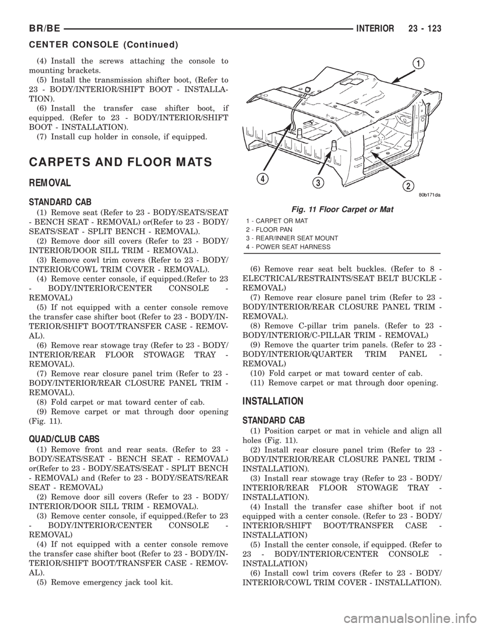
(9) Remove carpet or mat through door opening
(Fig. 11).
QUAD/CLUB CABS
(1) Remove front and rear seats. (Refer to 23 -
BODY/SEATS/SEAT - BENCH SEAT - REMOVAL)
or(Refer to 23 - BODY/SEATS/SEAT - SPLIT BENCH
- REMOVAL) and (Refer to 23 - BODY/SEATS/REAR
SEAT - REMOVAL)
(2) Remove door sill covers (Refer to 23 - BODY/
INTERIOR/DOOR SILL TRIM - REMOVAL).
(3) Remove center console, if equipped.(Refer to 23
- BODY/INTERIOR/CENTER CONSOLE -
REMOVAL)
(4) If not equipped with a center console remove
the transfer case shifter boot (Refer to 23 - BODY/IN-
TERIOR/SHIFT BOOT/TRANSFER CASE - REMOV-
AL).
(5) Remove emergency jack tool kit.(6) Remove rear seat belt buckles. (Refer to 8 -
ELECTRICAL/RESTRAINTS/SEAT BELT BUCKLE -
REMOVAL)
(7) Remove rear closure panel trim (Refer to 23 -
BODY/INTERIOR/REAR CLOSURE PANEL TRIM -
REMOVAL).
(8) Remove C-pillar trim panels. (Refer to 23 -
BODY/INTERIOR/C-PILLAR TRIM - REMOVAL)
(9) Remove the quarter trim panels. (Refer to 23 -
BODY/INTERIOR/QUARTER TRIM PANEL -
REMOVAL)
(10) Fold carpet or mat toward center of cab.
(11) Remove carpet or mat through door opening.
INSTALLATION
STANDARD CAB
(1) Position carpet or mat in vehicle and align all
holes (Fig. 11).
(2) Install rear closure panel trim (Refer to 23 -
BODY/INTERIOR/REAR CLOSURE PANEL TRIM -
INSTALLATION).
(3) Install rear stowage tray (Refer to 23 - BODY/
INTERIOR/REAR FLOOR STOWAGE TRAY -
INSTALLATION).
(4) Install the transfer case shifter boot if not
equipped with a center console. (Refer to 23 - BODY/
INTERIOR/SHIFT BOOT/TRANSFER CASE -
INSTALLATION)
(5) Install the center console, if equipped. (Refer to
23 - BODY/INTERIOR/CENTER CONSOLE -
INSTALLATION)
(6) Install cowl trim covers (Refer to 23 - BODY/
INTERIOR/COWL TRIM COVER - INSTALLATION).
Fig. 11 Floor Carpet or Mat
1 - CARPET OR MAT
2 - FLOOR PAN
3 - REAR/INNER SEAT MOUNT
4 - POWER SEAT HARNESS
BR/BEINTERIOR 23 - 123
CENTER CONSOLE (Continued)
Page 2697 of 2889
(7) Install door sill covers (Refer to 23 - BODY/IN-
TERIOR/DOOR SILL TRIM - INSTALLATION).
(8) Install seat, (Refer to 23 - BODY/SEATS/SEAT
- INSTALLATION) or (Refer to 23 - BODY/SEATS/
SEAT/SPLIT BENCH - INSTALLATION).
QUAD/CLUB CABS
(1) Position carpet or mat in vehicle.
(2) Install quarter trim panels. (Refer to 23 -
BODY/INTERIOR/QUARTER TRIM PANEL -
INSTALLATION)
(3) Install rear seat belt buckles.
(4) Install the C-pillar trim panels, if equipped.
(Refer to 23 - BODY/INTERIOR/C-PILLAR TRIM -
INSTALLATION)
(5) Install rear closure panel trim (Refer to 23 -
BODY/INTERIOR/REAR CLOSURE PANEL TRIM -
INSTALLATION).
(6) Install the rear seat belt buckles. (Refer to 8 -
ELECTRICAL/RESTRAINTS/SEAT BELT BUCKLE -
INSTALLATION)
(7) Install emergency jack tool kit.
(8) Install the transfer case shifter boot if not
equipped with a center console. (Refer to 23 - BODY/
INTERIOR/SHIFT BOOT/TRANSFER CASE -
INSTALLATION)
(9) Install the center console, if equipped. (Refer to
23 - BODY/INTERIOR/CENTER CONSOLE -
INSTALLATION)
(10) Install floor shift boot, if equipped.
(11) Install cowl trim covers (Refer to 23 - BODY/
INTERIOR/COWL TRIM COVER - INSTALLATION).
(12) Install door sill covers (Refer to 23 - BODY/
INTERIOR/DOOR SILL TRIM - INSTALLATION).
(13) Install front and rear seats. (Refer to 23 -
BODY/SEATS/SEAT - BENCH SEAT - INSTALLA-
TION) or (Refer to 23 - BODY/SEATS/SEAT - SPLIT
BENCH - INSTALLATION) and (Refer to 23 - BODY/
SEATS/REAR SEAT - INSTALLATION)
ASSIST HANDLE
REMOVAL
(1) Disengage tabs attaching assist handle end
covers to assist handle.
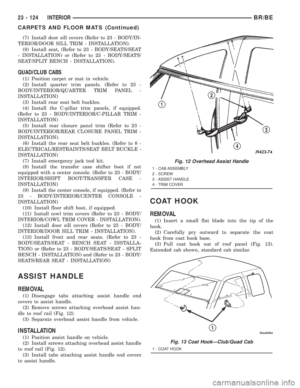
(2) Remove screws attaching overhead assist han-
dle to roof rail (Fig. 12).
(3) Separate overhead assist handle from vehicle.
INSTALLATION
(1) Position assist handle on vehicle.
(2) Install screws attaching overhead assist handle
to roof rail (Fig. 12).
(3) Install tabs attaching assist handle end covers
to assist handle.
COAT HOOK
REMOVAL
(1) Insert a small flat blade into the tip of the
hook.
(2) Carefully pry outward to separate the coat
hook from coat hook base.
(3) Pull coat hook out of roof panel (Fig. 13).
Extended cab shown, standard cab similar.
Fig. 12 Overhead Assist Handle
1 - CAB ASSEMBLY
2 - SCREW
3 - ASSIST HANDLE
4 - TRIM COVER
Fig. 13 Coat HookÐClub/Quad Cab
1 - COAT HOOK
23 - 124 INTERIORBR/BE
CARPETS AND FLOOR MATS (Continued)
Page 2698 of 2889
INSTALLATION
(1) Position coat hook in roof panel.
(2) Push the coat hook cover inward and secure
the coat hook to roof panel.
HEADLINER
REMOVAL
(1) Remove sun visors and visor hooks.(Refer to 23
- BODY/INTERIOR/SUN VISOR - REMOVAL).
(2) Remove overhead assist handle.(Refer to 23 -
BODY/INTERIOR/ASSIST HANDLE - REMOVAL).
(3) Remove coat hook(s).(Refer to 23 - BODY/IN-
TERIOR/COAT HOOK - REMOVAL)
(4) Remove overhead console, if equipped. (Refer to
8 - ELECTRICAL/OVERHEAD CONSOLE - REMOV-
AL).
(5) Remove A-pillar trim.(Refer to 23 - BODY/IN-
TERIOR/A-PILLAR TRIM - REMOVAL).
(6) Remove B-pillar trim panels. (Refer to 23 -
BODY/INTERIOR/B-PILLAR TRIM - REMOVAL).
(7) Remove the C-pillar trim panels, if equipped.
(Refer to 23 - BODY/INTERIOR/C-PILLAR TRIM -
REMOVAL)
(8) Remove the quarter trim panels, if equipped.
(Refer to 23 - BODY/INTERIOR/QUARTER TRIM
PANEL - REMOVAL)
(9) Remove dome lamp. (Refer to 8 - ELECTRI-
CAL/LAMPS/LIGHTING - INTERIOR/DOME LAMP
- REMOVAL).
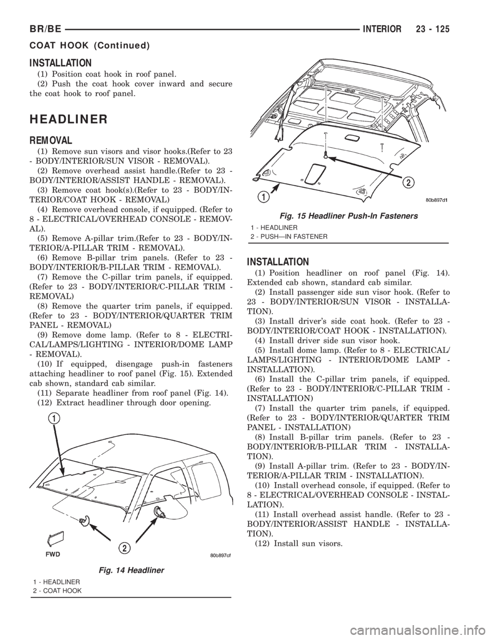
(10) If equipped, disengage push-in fasteners
attaching headliner to roof panel (Fig. 15). Extended
cab shown, standard cab similar.
(11) Separate headliner from roof panel (Fig. 14).
(12) Extract headliner through door opening.
INSTALLATION
(1) Position headliner on roof panel (Fig. 14).
Extended cab shown, standard cab similar.
(2) Install passenger side sun visor hook. (Refer to
23 - BODY/INTERIOR/SUN VISOR - INSTALLA-
TION).
(3) Install driver's side coat hook. (Refer to 23 -
BODY/INTERIOR/COAT HOOK - INSTALLATION).
(4) Install driver side sun visor hook.
(5) Install dome lamp. (Refer to 8 - ELECTRICAL/
LAMPS/LIGHTING - INTERIOR/DOME LAMP -
INSTALLATION).
(6) Install the C-pillar trim panels, if equipped.
(Refer to 23 - BODY/INTERIOR/C-PILLAR TRIM -
INSTALLATION)
(7) Install the quarter trim panels, if equipped.
(Refer to 23 - BODY/INTERIOR/QUARTER TRIM
PANEL - INSTALLATION)
(8) Install B-pillar trim panels. (Refer to 23 -
BODY/INTERIOR/B-PILLAR TRIM - INSTALLA-
TION).
(9) Install A-pillar trim. (Refer to 23 - BODY/IN-
TERIOR/A-PILLAR TRIM - INSTALLATION).
(10) Install overhead console, if equipped. (Refer to
8 - ELECTRICAL/OVERHEAD CONSOLE - INSTAL-
LATION).
(11) Install overhead assist handle. (Refer to 23 -
BODY/INTERIOR/ASSIST HANDLE - INSTALLA-
TION).
(12) Install sun visors.
Fig. 14 Headliner
1 - HEADLINER
2 - COAT HOOK
Fig. 15 Headliner Push-In Fasteners
1 - HEADLINER
2 - PUSHÐIN FASTENER
BR/BEINTERIOR 23 - 125
COAT HOOK (Continued)
Page 2699 of 2889
BODY VENT
REMOVAL
(1) Open door.
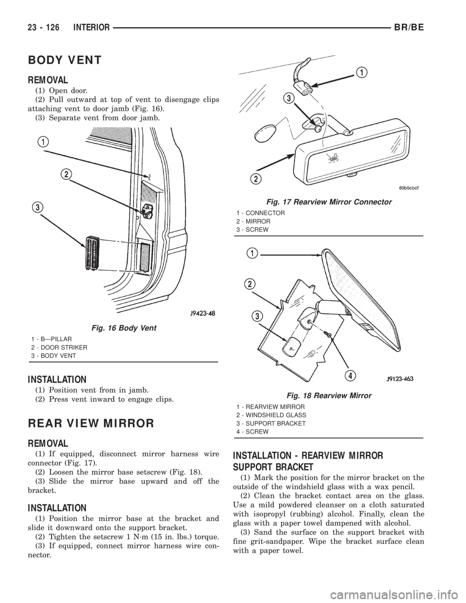
(2) Pull outward at top of vent to disengage clips
attaching vent to door jamb (Fig. 16).
(3) Separate vent from door jamb.
INSTALLATION
(1) Position vent from in jamb.
(2) Press vent inward to engage clips.
REAR VIEW MIRROR
REMOVAL
(1) If equipped, disconnect mirror harness wire
connector (Fig. 17).
(2) Loosen the mirror base setscrew (Fig. 18).
(3) Slide the mirror base upward and off the
bracket.
INSTALLATION
(1) Position the mirror base at the bracket and
slide it downward onto the support bracket.
(2) Tighten the setscrew 1 N´m (15 in. lbs.) torque.
(3) If equipped, connect mirror harness wire con-
nector.
INSTALLATION - REARVIEW MIRROR
SUPPORT BRACKET
(1) Mark the position for the mirror bracket on the
outside of the windshield glass with a wax pencil.
(2) Clean the bracket contact area on the glass.
Use a mild powdered cleanser on a cloth saturated
with isopropyl (rubbing) alcohol. Finally, clean the
glass with a paper towel dampened with alcohol.
(3) Sand the surface on the support bracket with
fine grit-sandpaper. Wipe the bracket surface clean
with a paper towel.
Fig. 16 Body Vent
1 - BÐPILLAR
2 - DOOR STRIKER
3 - BODY VENT
Fig. 17 Rearview Mirror Connector
1 - CONNECTOR
2 - MIRROR
3 - SCREW
Fig. 18 Rearview Mirror
1 - REARVIEW MIRROR
2 - WINDSHIELD GLASS
3 - SUPPORT BRACKET
4 - SCREW
23 - 126 INTERIORBR/BE
Page 2700 of 2889
(4) Apply accelerator to the surface on the bracket
according to the following instructions:
(a) Crush the vial to saturate the felt applicator.
(b) Remove the paper sleeve.
(c) Apply accelerator to the contact surface on
the bracket.
(d) Allow the accelerator to dry for five minutes.
(e) Do not touch the bracket contact surface
after the accelerator has been applied.
(5) Apply adhesive accelerator to the bracket con-
tact surface on the windshield glass. Allow the accel-
erator to dry for one minute. Do not touch the glass
contact surface after the accelerator has been
applied.
(6) Install the bracket according to the following
instructions:
(a) Apply one drop of adhesive at the center of
the bracket contact-surface on the windshield
glass.
(b) Apply an even coat of adhesive to the contact
surface on the bracket.
(c) Align the bracket with the marked position
on the windshield glass.
(d) Press and hold the bracket in place for at
least one minute.
NOTE: Verify that the mirror support bracket is cor-
rectly aligned, because the adhesive will cure rap-
idly.
(7) Allow the adhesive to cure for 8-10 minutes.
Remove any excess adhesive with an alcohol-damp-
ened cloth.
(8) Allow the adhesive to cure for an additional
8-10 minutes before installing the mirror.
SUN VISOR
REMOVAL
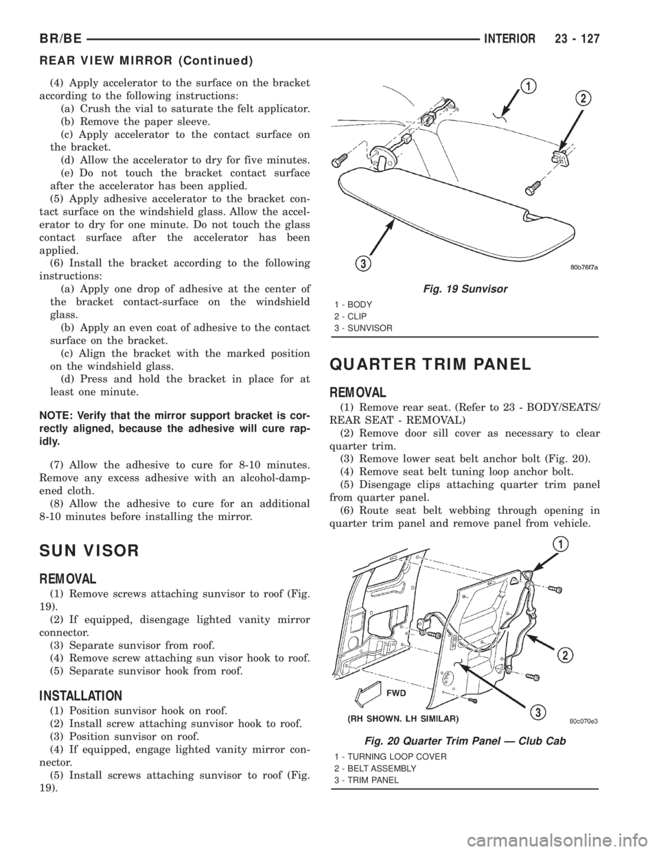
(1) Remove screws attaching sunvisor to roof (Fig.
19).
(2) If equipped, disengage lighted vanity mirror
connector.
(3) Separate sunvisor from roof.
(4) Remove screw attaching sun visor hook to roof.
(5) Separate sunvisor hook from roof.
INSTALLATION
(1) Position sunvisor hook on roof.
(2) Install screw attaching sunvisor hook to roof.
(3) Position sunvisor on roof.
(4) If equipped, engage lighted vanity mirror con-
nector.
(5) Install screws attaching sunvisor to roof (Fig.
19).
QUARTER TRIM PANEL
REMOVAL
(1) Remove rear seat. (Refer to 23 - BODY/SEATS/
REAR SEAT - REMOVAL)
(2) Remove door sill cover as necessary to clear
quarter trim.
(3) Remove lower seat belt anchor bolt (Fig. 20).
(4) Remove seat belt tuning loop anchor bolt.
(5) Disengage clips attaching quarter trim panel
from quarter panel.
(6) Route seat belt webbing through opening in
quarter trim panel and remove panel from vehicle.
Fig. 19 Sunvisor
1 - BODY
2 - CLIP
3 - SUNVISOR
Fig. 20 Quarter Trim Panel Ð Club Cab
1 - TURNING LOOP COVER
2 - BELT ASSEMBLY
3 - TRIM PANEL
BR/BEINTERIOR 23 - 127
REAR VIEW MIRROR (Continued)
Page 2701 of 2889
INSTALLATION
(1) Position trim panel in vehicle and route seat
belt webbing through opening in quarter trim panel.
(2) Open quarter vent window.
(3) Position trim panel on quarter panel and
engage clips on upper portion of panel.
(4) Engage clips attaching lower portion of quarter
trim panel to quarter panel.
(5) Install lower seat belt anchor bolt.
(6) Install door sill cover as necessary.
(7) Install rear seat. (Refer to 23 - BODY/SEATS/
REAR SEAT - INSTALLATION)
C-PILLAR TRIM
REMOVAL
(1) Remove rear floor stowage tray. (Refer to 23 -
BODY/INTERIOR/REAR FLOOR STOWAGE TRAY -
REMOVAL)
(2) Remove door sill cover as necessary to clear
C-pillar trim.
(3) Remove bolt attaching seat belt anchor to floor.
(4) Unsnap turning loop, push cover up and
remove bolt attaching turning loop to C-pillar.(5) Remove seat belt exit plug.
(6) Disengage clips attaching C-pillar trim to
upper C-pillar.
(7) Separate C-pillar trim from C-pillar.
(8) Route seat belt webbing through opening in
C-pillar trim.
INSTALLATION
(1) Route seat belt webbing through opening in
C-pillar trim.
(2) Position C-pillar trim at C-pillar.
(3) Starting at the top, engage clips attaching
C-pillar trim to upper C-pillar.
(4) Install seat belt exit plug.
(5) Install bolt attaching turning loop to C-pillar
and position turning loop cover. Snap turning loop
cover into place.
(6) Install bolt attaching seat belt anchor to floor.
(7) Install door sill cover.
(8) Install rear floor stowage tray. (Refer to 23 -
BODY/INTERIOR/REAR FLOOR STOWAGE TRAY -
INSTALLATION)
23 - 128 INTERIORBR/BE
QUARTER TRIM PANEL (Continued)
Page 2702 of 2889
PAINT
TABLE OF CONTENTS
page page
PAINT
SPECIFICATIONS........................129
BASE COAT/CLEAR COAT FINISH
DESCRIPTION..........................129
OPERATION............................129
PAINT CODE
DESCRIPTION..........................129PAINT TOUCH-UP
DESCRIPTION..........................129
WET SANDING/BUFFING & POLISHING
DESCRIPTION..........................130
PAINT
SPECIFICATIONS
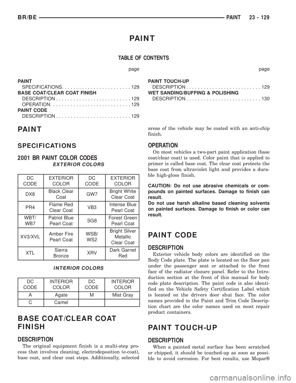
2001 BR PAINT COLOR CODES
EXTERIOR COLORS
DC
CODEEXTERIOR
COLORDC
CODEEXTERIOR
COLOR
DX8Black Clear
CoatGW7Bright White
Clear Coat
PR4Flame Red
Clear CoatVB3Intense Blue
Pearl Coat
WBT/
WB7Patriot Blue
Pearl CoatSG8Forest Green
Pearl Coat
XV3/XVLAmber Fire
Pearl CoatWSB/
WS2Bright Silver
Metallic
Clear Coat
XTLSierra
BronzeXRVDark Garnet
Red
INTERIOR COLORS
DC
CODEINTERIOR
COLORDC
CODEINTERIOR
COLOR
A Agate M Mist Gray
C Camel
BASE COAT/CLEAR COAT
FINISH
DESCRIPTION
The original equipment finish is a multi-step pro-
cess that involves cleaning, electrodeposition (e-coat),
base coat, and clear coat steps. Additionally, selectedareas of the vehicle may be coated with an anti-chip
finish.
OPERATION
On most vehicles a two-part paint application (base
coat/clear coat) is used. Color paint that is applied to
primer is called base coat. The clear coat protects the
base coat from ultraviolet light and provides a dura-
ble high-gloss finish.
CAUTION: Do not use abrasive chemicals or com-
pounds on painted surfaces. Damage to finish can
result.
Do not use harsh alkaline based cleaning solvents
on painted surfaces. Damage to finish or color can
result.
PAINT CODE
DESCRIPTION
Exterior vehicle body colors are identified on the
Body Code plate. The plate is located on the floor pan
under the passenger seat or attached to the front
face of the radiator closure panel. Refer to the Intro-
duction section at the front of this manual for body
code plate description. The paint code is also identi-
fied on the Vehicle Safety Certification Label which
is located on the drivers door shut face. The color
names provided in the Paint and Trim Code Descrip-
tion chart are the color names used on most repair
product containers.
PAINT TOUCH-UP
DESCRIPTION
When a painted metal surface has been scratched
or chipped, it should be touched-up as soon as possi-
ble to avoid corrosion. For best results, use Moparž
BR/BEPAINT 23 - 129
Page 2718 of 2889
STATIONARY GLASS
TABLE OF CONTENTS
page page
STATIONARY GLASS
DESCRIPTION..........................145
OPERATION............................145
BACKLITE
REMOVAL.............................145
INSTALLATION..........................145
BACKLITE LATCH AND KEEPER
REMOVAL.............................146
INSTALLATION..........................146
BACKLITE VENT GLASS
REMOVAL.............................147INSTALLATION..........................147
WINDSHIELD
DESCRIPTION..........................148
REMOVAL.............................148
INSTALLATION..........................148
QUARTER WINDOW
REMOVAL.............................151
INSTALLATION..........................151
STATIONARY GLASS
DESCRIPTION
Windshields are made of two pieces of glass with a
plastic inner layer. Windshields and selected station-
ary glass are structural members of the vehicle. The
windshield glass is bonded to the windshield frame
with urethane adhesive.
OPERATION
Windshields and other stationary glass protect the
occupants from the effects of the elements. Wind-
shields are also used to retain some airbags in posi-
tion during deployment. Urethane bonded glass is
difficult to salvage during removal. The urethane
bonding is difficult to cut or clean from any surface.
Before removing the glass, check the availability of
replacement components.
BACKLITE
REMOVAL
It is difficult to salvage the backlite during the
removal operation. The backlite is part of the struc-
tural support for the roof. The urethane bonding
used to secure the glass to the fence is difficult to cut
or clean from any surface. Since the molding is set in
urethane, it is unlikely it would be salvaged. Before
removing the backlite, check the availability from the
parts supplier.
The backlite is attached to the window frame with
urethane adhesive. The urethane adhesive is applied
cold and seals the surface area between the window
opening and the glass. The primer adheres the ure-
thane adhesive to the backlite.(1) Roll down door glass.
(2) Remove headliner. (Refer to 23 - BODY/INTE-
RIOR/HEADLINER - REMOVAL).
(3) Remove rear closer panel trim. (Refer to 23 -
BODY/INTERIOR/REAR CLOSURE PANEL TRIM -
REMOVAL).
(4) Bend backlite retaining tabs (Fig. 1) inward
against glass.
(5) Using a suitable pneumatic knife from inside
the vehicle, cut urethane holding backlite frame to
opening fence.
(6) Separate glass from vehicle.
INSTALLATION
(1) Clean urethane adhesive from around backlite
opening fence.
Fig. 1 Backlite Tabs
1 - BACKLITE
2-TAB
BR/BESTATIONARY GLASS 23 - 145