2001 DODGE RAM cummins
[x] Cancel search: cumminsPage 35 of 2889
99,000 Miles (156 000 km)
²Change engine oil.
²Replace engine oil filter.
²Lubricate tie rod ends every 3,000 miles (5 000
km).
²Inspect front wheel bearings (4x2).
102,000 Miles (163 000 km)
²Change engine oil.
²Replace engine oil filter.
²Lubricate tie rod ends every 3,000 miles (5 000
km).
²Inspect front wheel bearings (4x4).
105,000 Miles (168 000 km)
²Change engine oil.
²Replace engine oil filter.
²Lubricate tie rod ends every 3,000 miles (5 000
km).
108,000 Miles (173 000 km)
²Change engine oil.
²Replace engine oil filter.
²Inspect engine air cleaner element and air
pump filter, replace as necessary.
²Drain and refill automatic transmission fluid.
Replace filter and adjust bands.³
²Drain and refill transfer case fluid (4x4).
²Change rear axle fluid.
²Change front axle fluid (4x4).
²Inspect brake linings.
²Flush and replace engine coolant if it has been
30,000 miles (48 000 km) since last change.
²Lubricate tie rod ends every 3,000 miles (5 000
km).
²Inspect front wheel bearings (4x4).
²Inspect front wheel bearings (4x2).
*Requires Service Reminder Indicator Light. If so
equipped, these parts are to be replaced at the indi-
cated mileage or when the service reminder indicator
light remains on continuously with the key in the
ªONº position, whichever occurs first.
³Off-the-highway operation, trailer towing, snow
plowing, prolonged operation with heavy loading,
especially in hot weather require the more frequent
transmission service indicated witha³inSchedule
ªBº. Perform these services if you usually operate
your Ram Truck under these conditions.
Inspection and service should also be performed
anytime a malfunction is observed or suspected.
DESCRIPTION - MAINTENANCE SCHEDULES
Ð 24±VALVE CUMMINS TURBO DIESEL
There are two maintenance schedules that show
proper service for the vehicle.First is ScheduleªA.ºIt lists all the scheduled
maintenance to be performed under ªnormalº operat-
ing conditions.
Second is ScheduleªB.ºIt is a schedule for vehicles
that are operated under the conditions listed at the
beginning of that schedule.
Use the schedule that best describes the driving
conditions.
Where time and mileage are listed, follow the
interval that occurs first.
At Each Stop For Fuel
²Check engine oil level and add as required.
²Check windshield washer solvent and add if
required.
²Clean windshield and wiper blades as required.
²Drain water from fuel filter.
Once A Month
²Check tire pressure and look for unusual wear
or damage.
²Inspect battery and clean and tighten terminals
as required.
²Check fluid levels of coolant reservoir, brake
master cylinder, power steering, and transmission.
Add fluid as required.
²Check all lights and all other electrical items for
correct operation.
²Check Filter Mindery. Replace air cleaner
element if necessary.
²Inspect and clean wiper blades. Replace if
required.
At Each Oil Change
²Inspect exhaust system.
²Inspect brake hoses.
²Adjust rear brakes.
²Rotate the tires at each oil change interval
shown at 7, 5000 miles (12 000 km) on schedule ªAº
or every other interval shown at 7,500 miles (12 000
km) on schedule ªBº.
²Check engine coolant level, hoses, and clamps.
²Lubricate steering linkage.
²Drain crankcase breather canister (if equipped).
EMISSION CONTROL SYSTEM MAINTENANCE
The scheduled emission maintenance listed inbold
typeon the Maintenance Schedules, must be done at
the mileage specified to assure the continued proper
functioning of the emission control system. These,
and all other maintenance services included in this
manual, should be done to provide the best vehicle
performance and reliability. More frequent mainte-
nance may be needed for vehicles in severe operating
conditions such as dusty areas and very short trip
driving.
0 - 22 LUBRICATION & MAINTENANCEBR/BE
MAINTENANCE SCHEDULES (Continued)
Page 377 of 2889
COOLANT RECOVERY
CONTAINER - 8.0L
DESCRIPTION
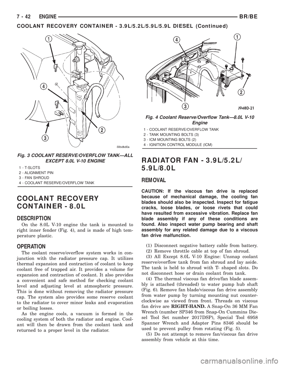
On the 8.0L V-10 engine the tank is mounted to
right inner fender (Fig. 4), and is made of high tem-
perature plastic.
OPERATION
The coolant reserve/overflow system works in con-
junction with the radiator pressure cap. It utilizes
thermal expansion and contraction of coolant to keep
coolant free of trapped air. It provides a volume for
expansion and contraction of coolant. It also provides
a convenient and safe method for checking coolant
level and adjusting level at atmospheric pressure.
This is done without removing the radiator pressure
cap. The system also provides some reserve coolant
to the radiator to cover minor leaks and evaporation
or boiling losses.
As the engine cools, a vacuum is formed in the
cooling system of both the radiator and engine. Cool-
ant will then be drawn from the coolant tank and
returned to a proper level in the radiator.
RADIATOR FAN - 3.9L/5.2L/
5.9L/8.0L
REMOVAL
CAUTION: If the viscous fan drive is replaced
because of mechanical damage, the cooling fan
blades should also be inspected. Inspect for fatigue
cracks, loose blades, or loose rivets that could
have resulted from excessive vibration. Replace fan
blade assembly if any of these conditions are
found. Also inspect water pump bearing and shaft
assembly for any related damage due to a viscous
fan drive malfunction.
(1) Disconnect negative battery cable from battery.
(2) Remove throttle cable at top of fan shroud.
(3) All Except 8.0L V-10 Engine: Unsnap coolant
reserve/overflow tank from fan shroud and lay aside.
The tank is held to shroud with T- shaped slots. Do
not disconnect hose or drain coolant from tank.
(4) The thermal viscous fan drive/fan blade assem-
bly is attached (threaded) to water pump hub shaft
(Fig. 6). Remove fan blade/viscous fan drive assembly
from water pump by turning mounting nut counter-
clockwise as viewed from front. Threads on viscous
fan drive areRIGHT-HAND.A Snap-On 36 MM Fan
Wrench (number SP346 from Snap-On Cummins Die-
sel Tool Set number 2017DSP), Special Tool 6958
Spanner Wrench and Adapter Pins 8346 should be
used to prevent pulley from rotating (Fig. 5).
(5) Do not attempt to remove fan/viscous fan drive
assembly from vehicle at this time.
Fig. 3 COOLANT RESERVE/OVERFLOW TANKÐALL
EXCEPT 8.0L V-10 ENGINE
1 - T-SLOTS
2 - ALIGNMENT PIN
3 - FAN SHROUD
4 - COOLANT RESERVE/OVERFLOW TANK
Fig. 4 Coolant Reserve/Overflow TankÐ8.0L V-10
Engine
1 - COOLANT RESERVE/OVERFLOW TANK
2 - TANK MOUNTING BOLTS (3)
3 - ICM MOUNTING BOLTS (2)
4 - IGNITION CONTROL MODULE (ICM)
7 - 42 ENGINEBR/BE
COOLANT RECOVERY CONTAINER - 3.9L/5.2L/5.9L/5.9L DIESEL (Continued)
Page 379 of 2889
(4) Install fan blade/viscous fan drive assembly to
water pump shaft (Fig. 6).
(5) Except 8.0L V-10 Engine: Install coolant
reserve/overflow tank to fan shroud. Snaps into posi-
tion.
(6) Install throttle cable to fan shroud.
(7) Connect negative battery cable.
NOTE: Viscous Fan Drive Fluid Pump Out Require-
ment: After installing a new viscous fan drive, bring
the engine speed up to approximately 2000 rpm and
hold for approximately two minutes. This will
ensure proper fluid distribution within the drive.
RADIATOR FAN - 5.9L DIESEL
REMOVAL
CAUTION: If the viscous fan drive is replaced
because of mechanical damage, the cooling fan
blades should also be inspected. Inspect for fatigue
cracks, loose blades, or loose rivets that could
have resulted from excessive vibration. Replace fan
blade assembly if any of these conditions are
found. Also inspect water pump bearing and shaft
assembly for any related damage due to a viscous
fan drive malfunction.
(1) Disconnect the battery negative cables.
(2) Remove the fan shroud mounting bolts. Posi-
tion fan shroud towards engine.
CAUTION: Do not remove the fan pulley bolts. This
pulley is under spring tension.
(3) The thermal viscous fan drive/fan blade assem-
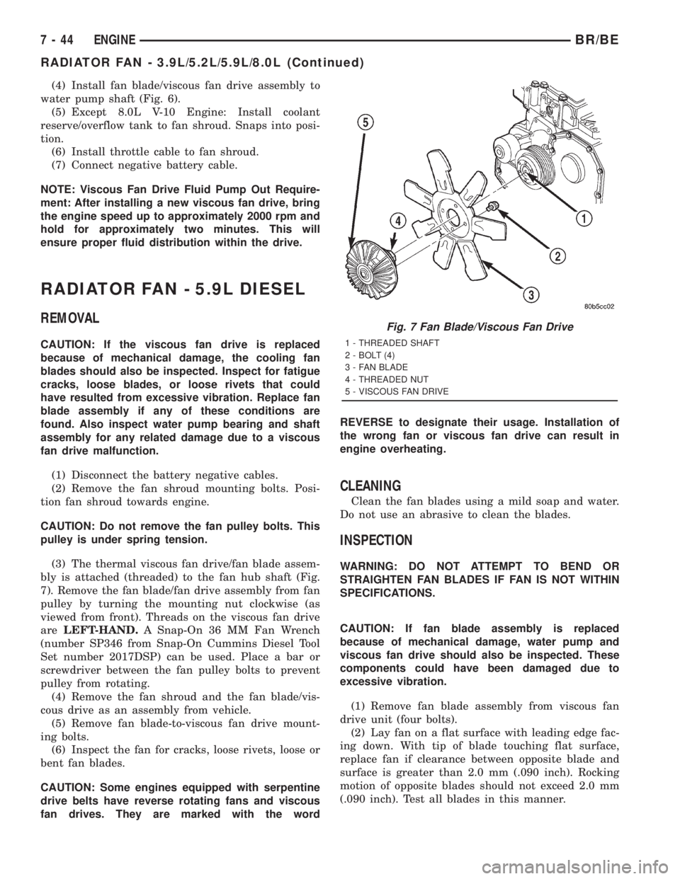
bly is attached (threaded) to the fan hub shaft (Fig.
7). Remove the fan blade/fan drive assembly from fan
pulley by turning the mounting nut clockwise (as
viewed from front). Threads on the viscous fan drive
areLEFT-HAND.A Snap-On 36 MM Fan Wrench
(number SP346 from Snap-On Cummins Diesel Tool
Set number 2017DSP) can be used. Place a bar or
screwdriver between the fan pulley bolts to prevent
pulley from rotating.
(4) Remove the fan shroud and the fan blade/vis-
cous drive as an assembly from vehicle.
(5) Remove fan blade-to-viscous fan drive mount-
ing bolts.
(6) Inspect the fan for cracks, loose rivets, loose or
bent fan blades.
CAUTION: Some engines equipped with serpentine
drive belts have reverse rotating fans and viscous
fan drives. They are marked with the wordREVERSE to designate their usage. Installation of
the wrong fan or viscous fan drive can result in
engine overheating.
CLEANING
Clean the fan blades using a mild soap and water.
Do not use an abrasive to clean the blades.
INSPECTION
WARNING: DO NOT ATTEMPT TO BEND OR
STRAIGHTEN FAN BLADES IF FAN IS NOT WITHIN
SPECIFICATIONS.
CAUTION: If fan blade assembly is replaced
because of mechanical damage, water pump and
viscous fan drive should also be inspected. These
components could have been damaged due to
excessive vibration.
(1) Remove fan blade assembly from viscous fan
drive unit (four bolts).
(2) Lay fan on a flat surface with leading edge fac-
ing down. With tip of blade touching flat surface,
replace fan if clearance between opposite blade and
surface is greater than 2.0 mm (.090 inch). Rocking
motion of opposite blades should not exceed 2.0 mm
(.090 inch). Test all blades in this manner.
Fig. 7 Fan Blade/Viscous Fan Drive
1 - THREADED SHAFT
2 - BOLT (4)
3 - FAN BLADE
4 - THREADED NUT
5 - VISCOUS FAN DRIVE
7 - 44 ENGINEBR/BE
RADIATOR FAN - 3.9L/5.2L/5.9L/8.0L (Continued)
Page 403 of 2889
(4) Disconnect the coolant reserve/overflow tank-
to-radiator hose at the tank.
(5) Remove the four fan shroud mounting bolts at
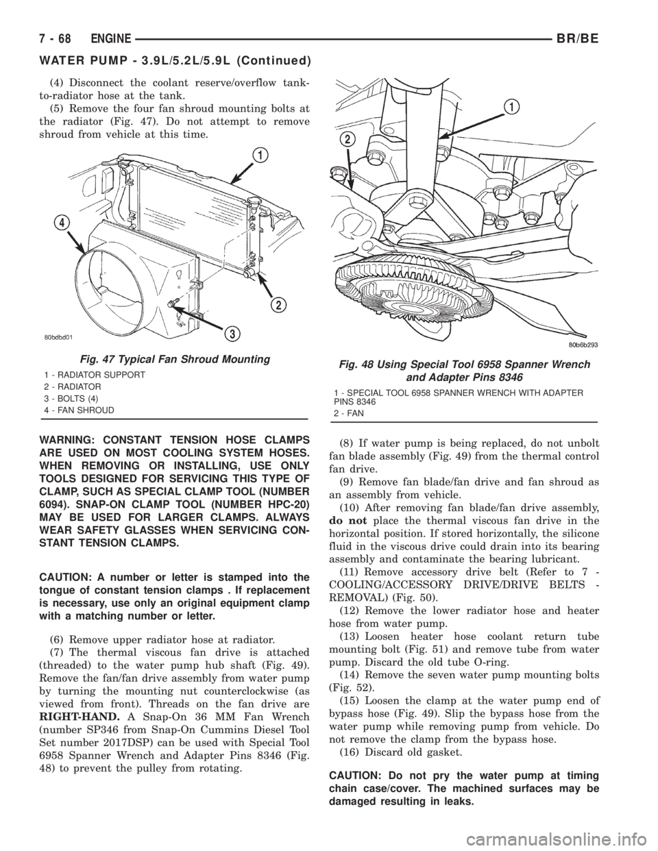
the radiator (Fig. 47). Do not attempt to remove
shroud from vehicle at this time.
WARNING: CONSTANT TENSION HOSE CLAMPS
ARE USED ON MOST COOLING SYSTEM HOSES.
WHEN REMOVING OR INSTALLING, USE ONLY
TOOLS DESIGNED FOR SERVICING THIS TYPE OF
CLAMP, SUCH AS SPECIAL CLAMP TOOL (NUMBER
6094). SNAP-ON CLAMP TOOL (NUMBER HPC-20)
MAY BE USED FOR LARGER CLAMPS. ALWAYS
WEAR SAFETY GLASSES WHEN SERVICING CON-
STANT TENSION CLAMPS.
CAUTION: A number or letter is stamped into the
tongue of constant tension clamps . If replacement
is necessary, use only an original equipment clamp
with a matching number or letter.
(6) Remove upper radiator hose at radiator.
(7) The thermal viscous fan drive is attached
(threaded) to the water pump hub shaft (Fig. 49).
Remove the fan/fan drive assembly from water pump
by turning the mounting nut counterclockwise (as
viewed from front). Threads on the fan drive are
RIGHT-HAND.A Snap-On 36 MM Fan Wrench
(number SP346 from Snap-On Cummins Diesel Tool
Set number 2017DSP) can be used with Special Tool
6958 Spanner Wrench and Adapter Pins 8346 (Fig.
48) to prevent the pulley from rotating.(8) If water pump is being replaced, do not unbolt
fan blade assembly (Fig. 49) from the thermal control
fan drive.
(9) Remove fan blade/fan drive and fan shroud as
an assembly from vehicle.
(10) After removing fan blade/fan drive assembly,
do notplace the thermal viscous fan drive in the
horizontal position. If stored horizontally, the silicone
fluid in the viscous drive could drain into its bearing
assembly and contaminate the bearing lubricant.
(11) Remove accessory drive belt (Refer to 7 -
COOLING/ACCESSORY DRIVE/DRIVE BELTS -
REMOVAL) (Fig. 50).
(12) Remove the lower radiator hose and heater
hose from water pump.
(13) Loosen heater hose coolant return tube
mounting bolt (Fig. 51) and remove tube from water
pump. Discard the old tube O-ring.
(14) Remove the seven water pump mounting bolts
(Fig. 52).
(15) Loosen the clamp at the water pump end of
bypass hose (Fig. 49). Slip the bypass hose from the
water pump while removing pump from vehicle. Do
not remove the clamp from the bypass hose.
(16) Discard old gasket.
CAUTION: Do not pry the water pump at timing
chain case/cover. The machined surfaces may be
damaged resulting in leaks.
Fig. 47 Typical Fan Shroud Mounting
1 - RADIATOR SUPPORT
2 - RADIATOR
3 - BOLTS (4)
4 - FAN SHROUDFig. 48 Using Special Tool 6958 Spanner Wrench
and Adapter Pins 8346
1 - SPECIAL TOOL 6958 SPANNER WRENCH WITH ADAPTER
PINS 8346
2-FAN
7 - 68 ENGINEBR/BE
WATER PUMP - 3.9L/5.2L/5.9L (Continued)
Page 406 of 2889
CAUTION: A number or letter is stamped into the
tongue of constant tension clamps. If replacement
is necessary, use only an original equipment clamp
with a matching number or letter.
(5) Remove radiator upper hose at radiator.
(6) The thermal viscous fan drive is attached
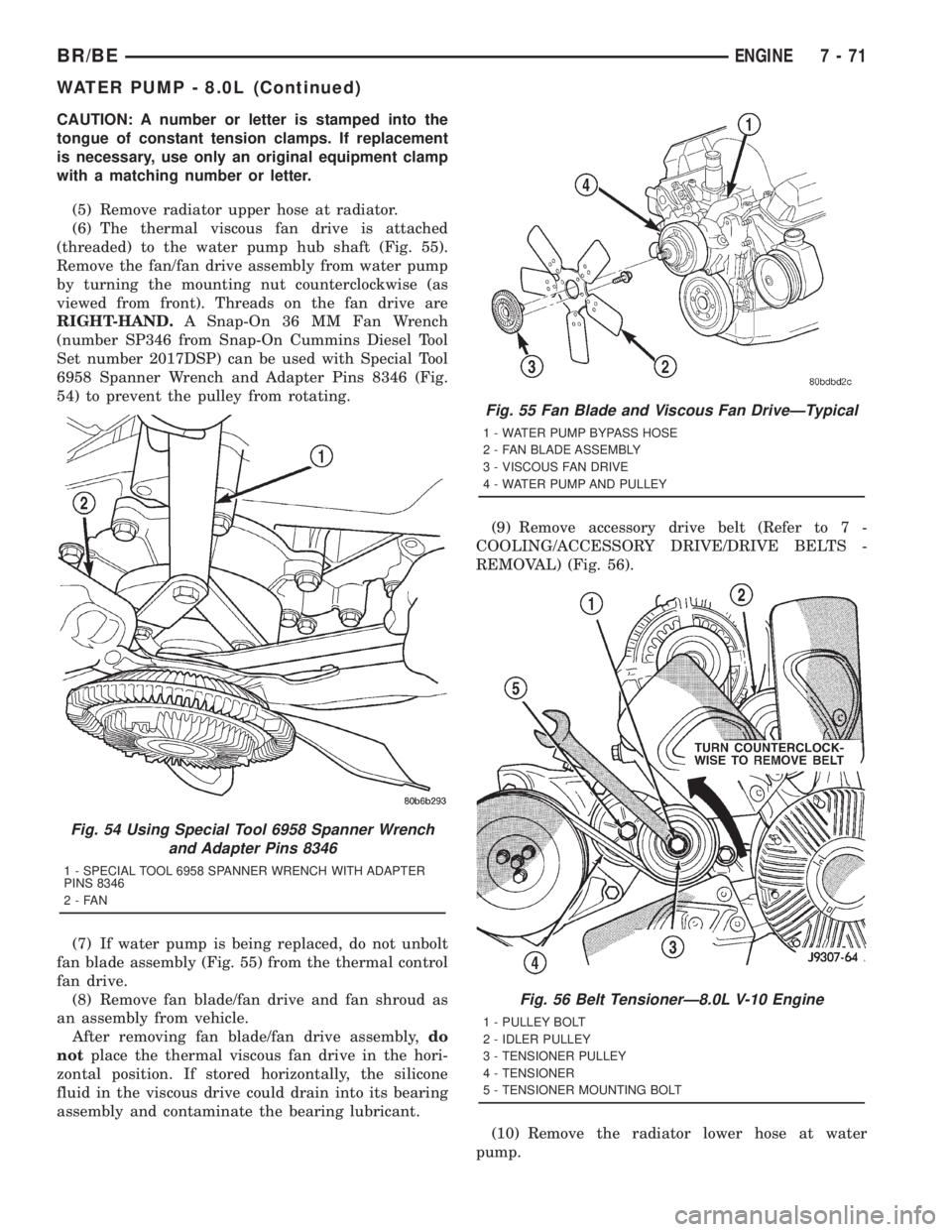
(threaded) to the water pump hub shaft (Fig. 55).
Remove the fan/fan drive assembly from water pump
by turning the mounting nut counterclockwise (as
viewed from front). Threads on the fan drive are
RIGHT-HAND.A Snap-On 36 MM Fan Wrench
(number SP346 from Snap-On Cummins Diesel Tool
Set number 2017DSP) can be used with Special Tool
6958 Spanner Wrench and Adapter Pins 8346 (Fig.
54) to prevent the pulley from rotating.
(7) If water pump is being replaced, do not unbolt
fan blade assembly (Fig. 55) from the thermal control
fan drive.
(8) Remove fan blade/fan drive and fan shroud as
an assembly from vehicle.
After removing fan blade/fan drive assembly,do
notplace the thermal viscous fan drive in the hori-
zontal position. If stored horizontally, the silicone
fluid in the viscous drive could drain into its bearing
assembly and contaminate the bearing lubricant.(9) Remove accessory drive belt (Refer to 7 -
COOLING/ACCESSORY DRIVE/DRIVE BELTS -
REMOVAL) (Fig. 56).
(10) Remove the radiator lower hose at water
pump.
Fig. 54 Using Special Tool 6958 Spanner Wrench
and Adapter Pins 8346
1 - SPECIAL TOOL 6958 SPANNER WRENCH WITH ADAPTER
PINS 8346
2-FAN
Fig. 55 Fan Blade and Viscous Fan DriveÐTypical
1 - WATER PUMP BYPASS HOSE
2 - FAN BLADE ASSEMBLY
3 - VISCOUS FAN DRIVE
4 - WATER PUMP AND PULLEY
Fig. 56 Belt TensionerÐ8.0L V-10 Engine
1 - PULLEY BOLT
2 - IDLER PULLEY
3 - TENSIONER PULLEY
4 - TENSIONER
5 - TENSIONER MOUNTING BOLT
BR/BEENGINE 7 - 71
WATER PUMP - 8.0L (Continued)
Page 756 of 2889

8W-02 COMPONENT INDEX
Component Page
4WD Switch.......................... 8W-31
A/C Compressor Clutch Relay............ 8W-42
A/C Compressor Clutch................. 8W-42
A/C-Heater Control.................... 8W-42
A/C Heater Temperature Select........... 8W-42
A/C High Pressure Switch............... 8W-42
A/C Low Pressure Switch................ 8W-42
Accelerator Pedal Position Sensor......... 8W-30
Aftermarket Center High Mounted
Stop Lamp......................... 8W-51
Aftermarket Trailer Tow Connector........ 8W-54
Airbag Control Module.................. 8W-43
Ambient Temperature Sensor............ 8W-49
Ash Receiver Lamp.................... 8W-44
Automatic Day/Night Mirror............. 8W-49
Automatic Shut Down Relay............. 8W-30
Auxiliary Battery...................... 8W-20
Back-Up Lamp Switch.................. 8W-51
Back-Up Lamps....................... 8W-51
Battery Temperature Sensor............. 8W-30
Battery............................. 8W-20
Blend Door Actuator................... 8W-42
Blower Motor Relay.................... 8W-42
Blower Motor Resistor Block............. 8W-42
Blower Motor......................... 8W-42
Brake Lamp Switch.................... 8W-51
Brake Pressure Switch............... 8W-34, 35
Bypass Jumper....................... 8W-21
Camshaft Position Sensor............... 8W-30
Capacitor......................... 8W-10, 30
Cargo Lamps......................... 8W-44
Center High Mounted Stop Lamps........ 8W-51
Center Identification Lamp.............. 8W-50
Central Timer Module.................. 8W-45
Cigar Lighter......................... 8W-41
Circuit Breakers...................... 8W-12
Clockspring.................. 8W-33, 41, 43, 47
Clutch Pedal Position Switch............. 8W-21
Combination Flasher................... 8W-52
Controller Antilock Brake............ 8W-34, 35
Crankshaft Position Sensor.............. 8W-30
Cummins Bus........................ 8W-18
Cup Holder Lamp..................... 8W-44
Cylinder Lock Switches................ 8W-39
Data Link Connector................... 8W-18
Daytime Running Lamp Module.......... 8W-50
Dome Lamp.......................... 8W-44
Door Ajar Switches.................... 8W-45
Door Lock Motors..................... 8W-61
Door Window/Lock Switches.......... 8W-60, 61
Driver Airbag......................... 8W-43
Duty Cycle EVAP/Purge Solenoid......... 8W-30Component Page
Electric Brake Provision................ 8W-54
Engine Control Module.............. 8W-30, 70
Engine Coolant Temperature Sensor....... 8W-30
Engine Oil Pressure Sensor.............. 8W-30
Engine Starter Motor Relay.............. 8W-21
Engine Starter Motor................... 8W-21
Fender Lamp......................... 8W-51
Fog Lamp Indicator.................... 8W-50
Fog Lamp Relay....................... 8W-50
Fog Lamp............................ 8W-50
Fuel Heater Relay..................... 8W-30
Fuel Heater.......................... 8W-30
Fuel Injection Pump................... 8W-30
Fuel Injectors......................... 8W-30
Fuel Transfer Pump.................... 8W-30
Fuses (JB)........................... 8W-12
Fuses (PDC).......................... 8W-10
Fusible Link....................... 8W-20, 30
Generator............................ 8W-20
Glove Box Lamp And Switch............. 8W-44
Grounds............................. 8W-15
Headlamp Beam Select Switch........... 8W-50
Headlamp Switch...................... 8W-50
Headlamp........................... 8W-50
Heated Mirror Relay................... 8W-62
Heated Mirror Switch.................. 8W-62
Heated Seat Cushions.................. 8W-63
Heated Seat Relay..................... 8W-12
Heated Seat Switches.................. 8W-63
High Beam Indicator................... 8W-40
High Note Horn....................... 8W-41
Horn Relay.......................... 8W-41
Horn Switch.......................... 8W-41
Idle Air Control Motor.................. 8W-30
Ignition Coil 4-Pack.................... 8W-30
Ignition Coil 6-Pack.................... 8W-30
Ignition Coil.......................... 8W-30
Ignition Switch....................... 8W-10
Instrument Cluster.................... 8W-40
Intake Air Heater Relays................ 8W-30
Intake Air Heater..................... 8W-30
Intake Air Temperature Sensor........... 8W-30
Intermittent Wiper Switch............... 8W-53
Joint Connectors . . 8W-10, 12, 15, 30, 31, 34, 35, 40,
44, 45, 51, 53, 70
Junction Block........................ 8W-12
Leak Detection Pump.................. 8W-30
License Lamp......................... 8W-51
Low Note Horn....................... 8W-41
Lumbar Motors....................... 8W-63
Manifold Absolute Pressure Sensor........ 8W-30
Manifold Air Pressure Sensor............ 8W-30
BR/BE8W-02 COMPONENT INDEX 8W - 02 - 1
Page 808 of 2889

8W-15 GROUND DISTRIBUTION
Component Page
A/C Compressor Clutch............... 8W-15-10, 8
A/C-Heater Control.................... 8W-15-14
A/C Heater Temperature Select........... 8W-15-12
Aftermarket Trailer Tow Connector......... 8W-15-6
Airbag Control Module.................. 8W-15-5
Ash Receiver Lamp.................... 8W-15-14
Automatic Day/Night Mirror............. 8W-15-13
Auxiliary Battery..................... 8W-15-11
Battery............................ 8W-15-11
Blend Door Actuator................... 8W-15-12
Blower Motor Relay.................... 8W-15-2
Brake Lamp Switch................... 8W-15-12
Brake Pressure Switch.................. 8W-15-3
Center High Mounted Stop Lamp No. 1..... 8W-15-17
Center High Mounted Stop Lamp No. 2..... 8W-15-17
Center Identification Lamp.............. 8W-15-18
Central Timer Module C1............... 8W-15-12
Central Timer Module C2............... 8W-15-13
Cigar Lighter........................ 8W-15-14
Clockspring.......................... 8W-15-4
Combination Flasher.................. 8W-15-13
Controller Antilock Brake................ 8W-15-5
Cummins Bus....................... 8W-15-10
Cup Holder Lamp..................... 8W-15-14
Data Link Connector.............. 8W-15-8, 10, 12
Daytime Running Lamp Module......... 8W-15-2, 3
Driver Cylinder Lock Switch............. 8W-15-16
Driver Door Ajar Switch................ 8W-15-16
Driver Door Window/Lock Switch....... 8W-15-16, 17
Driver Heated Seat Cushion............. 8W-15-15
Driver Heated Seat Switch.............. 8W-15-13
Driver Power Seat Switch............ 8W-15-15, 17
Electric Brake Provision................ 8W-15-14
Engine Control Module.................. 8W-15-9
Engine Starter Motor Relay............. 8W-15-8, 9
Fuel Heater Relay..................... 8W-15-2
Fuel Heater......................... 8W-15-10
Fuel Injection Pump.................... 8W-15-9
Fuel Pump Module..................... 8W-15-7
Fuel Pump Relay...................... 8W-15-2
Fuel Transfer Pump................... 8W-15-10
G100.......................... 8W-15-12, 5, 7
G101............................... 8W-15-5
G102............................... 8W-15-2
G105............................... 8W-15-8
G107.............................. 8W-15-10
G113 .............................. 8W-15-11
G114 .............................. 8W-15-11
G115 .............................. 8W-15-11
G116 .............................. 8W-15-11
G117 .............................. 8W-15-11
G118 .............................. 8W-15-11
G120.............................. 8W-15-11
G200......................... 8W-15-7, 12, 14
G201........................... 8W-15-12, 14
G300.............................. 8W-15-16
G301.............................. 8W-15-17
G302.............................. 8W-15-18
Glove Box Lamp And Switch............. 8W-15-14
Headlamp Beam Select Switch............ 8W-15-14
Headlamp Switch.................. 8W-15-13, 14
Heated Mirror Switch.................. 8W-15-13
High Note Horn....................... 8W-15-7
Ignition Switch....................... 8W-15-13
Instrument Cluster................. 8W-15-12, 14
Intake Air Heater Relay No. 1............. 8W-15-9Component Page
Intake Air Heater Relay No. 2............. 8W-15-9
Joint Connector No. 1................... 8W-15-2
Joint Connector No. 2................... 8W-15-9
Joint Connector No. 3................... 8W-15-7
Joint Connector No. 4................... 8W-15-3
Joint Connector No. 5.................. 8W-15-13
Joint Connector No. 6................... 8W-15-4
Joint Connector No. 8................ 8W-15-13, 5
Junction Block.................... 8W-15-12, 13
Left Back-Up Lamp.................... 8W-15-6
Left Front Door Speaker................. 8W-15-4
Left Front Fender Lamp................. 8W-15-6
Left License Lamp..................... 8W-15-6
Left Outboard Clearance Lamp........... 8W-15-18
Left Outboard Identification Lamp......... 8W-15-18
Left Park/Turn Signal Lamp.............. 8W-15-3
Left Power Mirror..................... 8W-15-16
Left Rear Fender Lamp................. 8W-15-6
Left Remote Radio Switch................ 8W-15-4
Left Tail/Stop/Turn Signal Lamp........... 8W-15-6
Left Visor/Vanity Lamp................. 8W-15-13
Low Note Horn....................... 8W-15-7
Overdrive Switch..................... 8W-15-12
Overhead Console..................... 8W-15-12
Oxygen Sensor 1/2 Left Bank Down......... 8W-15-8
Oxygen Sensor 1/2 Pre-Catalyst............ 8W-15-8
Oxygen Sensor 1/3 Post-Catalyst........... 8W-15-8
Oxygen Sensor 2/2 Right Bank Down........ 8W-15-8
Passenger Airbag On/Off Switch........... 8W-15-5
Passenger Cylinder Lock Switch.......... 8W-15-16
Passenger Door Ajar Switch.............. 8W-15-16
Passenger Door Window/Lock Switch....... 8W-15-16
Passenger Heated Seat Cushion........... 8W-15-15
Passenger Heated Seat Switch............ 8W-15-13
Passenger Power Seat Switch............ 8W-15-15
Power Distribution Center............... 8W-15-2
Power Mirror Switch................... 8W-15-16
Power Outlet........................ 8W-15-14
Powertrain Control Module............ 8W-15-8 , 10
Quad High Beam Relay................. 8W-15-2
Radio Choke Relay..................... 8W-15-4
Radio.............................. 8W-15-5
Right Back-Up Lamp................... 8W-15-6
Right Front Door Speaker................ 8W-15-4
Right Front Fender Lamp................ 8W-15-6
Right License Lamp.................... 8W-15-6
Right Outboard Clearance Lamp.......... 8W-15-18
Right Outboard Identification Lamp........ 8W-15-18
Right Park/Turn Signal Lamp............. 8W-15-7
Right Power Mirror................... 8W-15-16
Right Rear Fender Lamp................ 8W-15-6
Right Remote Radio Switch............... 8W-15-4
Right Tail/Stop/Turn Signal Lamp.......... 8W-15-6
Right Visor/Vanity Lamp................ 8W-15-13
Seat Belt Switch................... 8W-15-15, 17
Seat Heat Interface Module.............. 8W-15-15
Security Relay........................ 8W-15-2
Speed Control Servo.................... 8W-15-3
Tailgate Lamp........................ 8W-15-6
Trailer Tow Connector.................. 8W-15-6
Trailer Tow Relay...................... 8W-15-2
Underhood Lamp...................... 8W-15-3
Washer Fluid Level Switch............... 8W-15-3
Windshield Washer Pump................ 8W-15-7
Wiper Motor......................... 8W-15-7
BR/BE8W-15 GROUND DISTRIBUTION 8W - 15 - 1
Page 826 of 2889
8W-18 BUS COMMUNICATIONS
Component Page
Cummins Bus....................... 8W-18-4
Data Link Connector................ 8W-18-2, 3
Engine Control Module.............. 8W-18-3, 4
Fuse 12 (JB)...................... 8W-18-2, 3
G105.............................. 8W-18-2
G107.............................. 8W-18-4Component Page
G200............................ 8W-18-2, 3
Joint Connector No. 5............... 8W-18-2, 3
Joint Connector No. 7............... 8W-18-2, 3
Junction Block.................... 8W-18-2, 3
Powertrain Control Module........... 8W-18-2, 3
BR/BE8W-18 BUS COMMUNICATIONS 8W - 18 - 1