2001 DODGE RAM cummins
[x] Cancel search: cumminsPage 838 of 2889
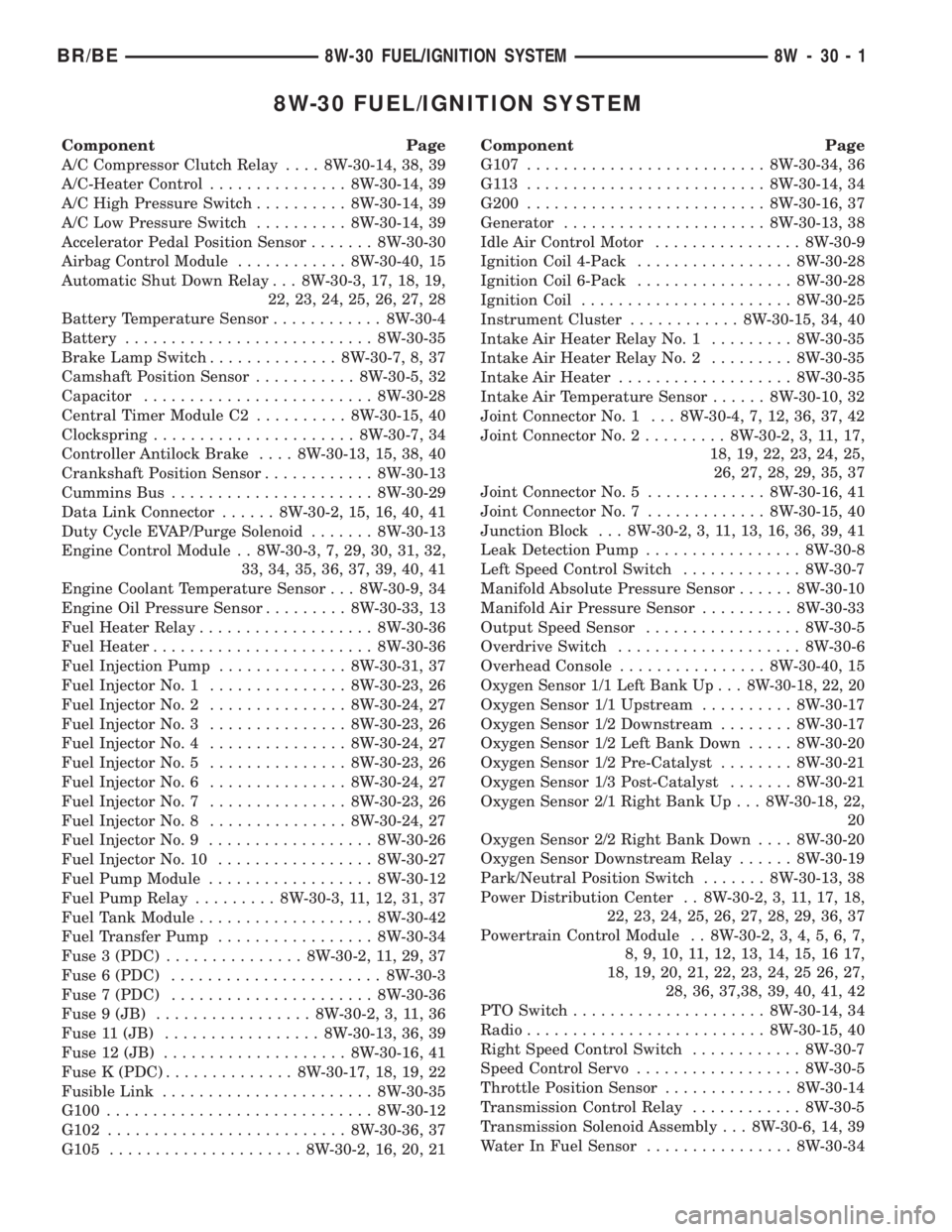
8W-30 FUEL/IGNITION SYSTEM
Component Page
A/C Compressor Clutch Relay.... 8W-30-14, 38, 39
A/C-Heater Control............... 8W-30-14, 39
A/C High Pressure Switch.......... 8W-30-14, 39
A/C Low Pressure Switch.......... 8W-30-14, 39
Accelerator Pedal Position Sensor....... 8W-30-30
Airbag Control Module............ 8W-30-40, 15
Automatic Shut Down Relay . . . 8W-30-3, 17, 18, 19,
22, 23, 24, 25, 26, 27, 28
Battery Temperature Sensor............ 8W-30-4
Battery........................... 8W-30-35
Brake Lamp Switch.............. 8W-30-7, 8, 37
Camshaft Position Sensor........... 8W-30-5, 32
Capacitor......................... 8W-30-28
Central Timer Module C2.......... 8W-30-15, 40
Clockspring...................... 8W-30-7, 34
Controller Antilock Brake.... 8W-30-13, 15, 38, 40
Crankshaft Position Sensor............ 8W-30-13
Cummins Bus...................... 8W-30-29
Data Link Connector...... 8W-30-2, 15, 16, 40, 41
Duty Cycle EVAP/Purge Solenoid....... 8W-30-13
Engine Control Module . . 8W-30-3, 7, 29, 30, 31, 32,
33, 34, 35, 36, 37, 39, 40, 41
Engine Coolant Temperature Sensor . . . 8W-30-9, 34
Engine Oil Pressure Sensor......... 8W-30-33, 13
Fuel Heater Relay................... 8W-30-36
Fuel Heater........................ 8W-30-36
Fuel Injection Pump.............. 8W-30-31, 37
Fuel Injector No. 1............... 8W-30-23, 26
Fuel Injector No. 2............... 8W-30-24, 27
Fuel Injector No. 3............... 8W-30-23, 26
Fuel Injector No. 4............... 8W-30-24, 27
Fuel Injector No. 5............... 8W-30-23, 26
Fuel Injector No. 6............... 8W-30-24, 27
Fuel Injector No. 7............... 8W-30-23, 26
Fuel Injector No. 8............... 8W-30-24, 27
Fuel Injector No. 9.................. 8W-30-26
Fuel Injector No. 10................. 8W-30-27
Fuel Pump Module.................. 8W-30-12
Fuel Pump Relay......... 8W-30-3, 11, 12, 31, 37
Fuel Tank Module................... 8W-30-42
Fuel Transfer Pump................. 8W-30-34
Fuse 3 (PDC)............... 8W-30-2, 11, 29, 37
Fuse 6 (PDC)....................... 8W-30-3
Fuse 7 (PDC)...................... 8W-30-36
Fuse 9 (JB)................. 8W-30-2, 3, 11, 36
Fuse 11 (JB)................. 8W-30-13, 36, 39
Fuse 12 (JB).................... 8W-30-16, 41
Fuse K (PDC).............. 8W-30-17, 18, 19, 22
Fusible Link....................... 8W-30-35
G100............................. 8W-30-12
G102.......................... 8W-30-36, 37
G105..................... 8W-30-2, 16, 20, 21Component Page
G107.......................... 8W-30-34, 36
G113 .......................... 8W-30-14, 34
G200.......................... 8W-30-16, 37
Generator...................... 8W-30-13, 38
Idle Air Control Motor................ 8W-30-9
Ignition Coil 4-Pack................. 8W-30-28
Ignition Coil 6-Pack................. 8W-30-28
Ignition Coil....................... 8W-30-25
Instrument Cluster............ 8W-30-15, 34, 40
Intake Air Heater Relay No. 1......... 8W-30-35
Intake Air Heater Relay No. 2......... 8W-30-35
Intake Air Heater................... 8W-30-35
Intake Air Temperature Sensor...... 8W-30-10, 32
Joint Connector No. 1 . . . 8W-30-4, 7, 12, 36, 37, 42
Joint Connector No. 2......... 8W-30-2, 3, 11, 17,
18, 19, 22, 23, 24, 25,
26, 27, 28, 29, 35, 37
Joint Connector No. 5............. 8W-30-16, 41
Joint Connector No. 7............. 8W-30-15, 40
Junction Block . . . 8W-30-2, 3, 11, 13, 16, 36, 39, 41
Leak Detection Pump................. 8W-30-8
Left Speed Control Switch............. 8W-30-7
Manifold Absolute Pressure Sensor...... 8W-30-10
Manifold Air Pressure Sensor.......... 8W-30-33
Output Speed Sensor................. 8W-30-5
Overdrive Switch.................... 8W-30-6
Overhead Console................ 8W-30-40, 15
Oxygen Sensor 1/1 Left Bank Up . . . 8W-30-18, 22, 20
Oxygen Sensor 1/1 Upstream.......... 8W-30-17
Oxygen Sensor 1/2 Downstream........ 8W-30-17
Oxygen Sensor 1/2 Left Bank Down..... 8W-30-20
Oxygen Sensor 1/2 Pre-Catalyst........ 8W-30-21
Oxygen Sensor 1/3 Post-Catalyst....... 8W-30-21
Oxygen Sensor 2/1 Right Bank Up . . . 8W-30-18, 22,
20
Oxygen Sensor 2/2 Right Bank Down.... 8W-30-20
Oxygen Sensor Downstream Relay...... 8W-30-19
Park/Neutral Position Switch....... 8W-30-13, 38
Power Distribution Center . . 8W-30-2, 3, 11, 17, 18,
22, 23, 24, 25, 26, 27, 28, 29, 36, 37
Powertrain Control Module . . 8W-30-2, 3, 4, 5, 6, 7,
8, 9, 10, 11, 12, 13, 14, 15, 16 17,
18, 19, 20, 21, 22, 23, 24, 25 26, 27,
28, 36, 37,38, 39, 40, 41, 42
PTO Switch..................... 8W-30-14, 34
Radio.......................... 8W-30-15, 40
Right Speed Control Switch............ 8W-30-7
Speed Control Servo.................. 8W-30-5
Throttle Position Sensor.............. 8W-30-14
Transmission Control Relay............ 8W-30-5
Transmission Solenoid Assembly . . . 8W-30-6, 14, 39
Water In Fuel Sensor................ 8W-30-34
BR/BE8W-30 FUEL/IGNITION SYSTEM 8W - 30 - 1
Page 1015 of 2889
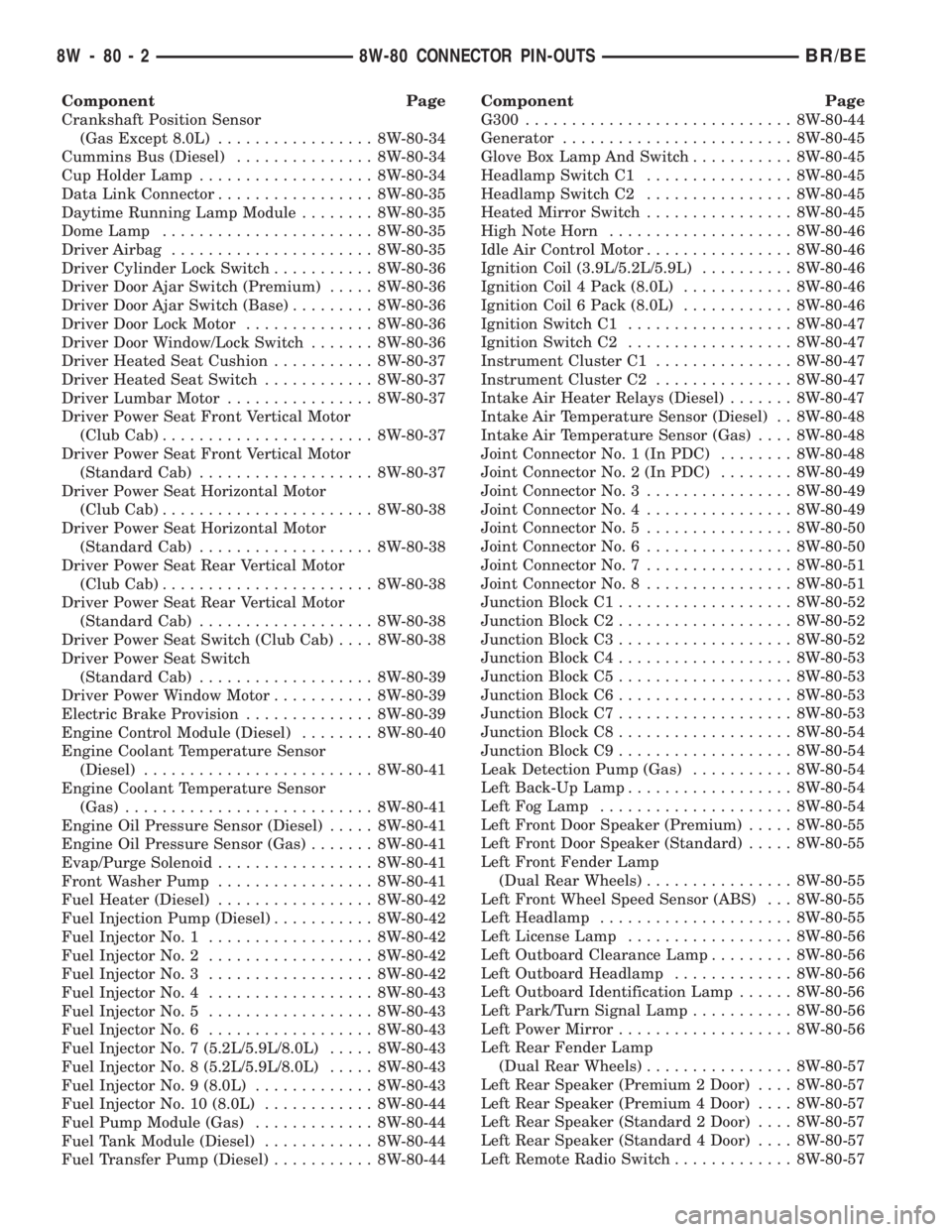
Component Page
Crankshaft Position Sensor
(Gas Except 8.0L)................. 8W-80-34
Cummins Bus (Diesel)............... 8W-80-34
Cup Holder Lamp................... 8W-80-34
Data Link Connector................. 8W-80-35
Daytime Running Lamp Module........ 8W-80-35
Dome Lamp....................... 8W-80-35
Driver Airbag...................... 8W-80-35
Driver Cylinder Lock Switch........... 8W-80-36
Driver Door Ajar Switch (Premium)..... 8W-80-36
Driver Door Ajar Switch (Base)......... 8W-80-36
Driver Door Lock Motor.............. 8W-80-36
Driver Door Window/Lock Switch....... 8W-80-36
Driver Heated Seat Cushion........... 8W-80-37
Driver Heated Seat Switch............ 8W-80-37
Driver Lumbar Motor................ 8W-80-37
Driver Power Seat Front Vertical Motor
(Club Cab)....................... 8W-80-37
Driver Power Seat Front Vertical Motor
(Standard Cab)................... 8W-80-37
Driver Power Seat Horizontal Motor
(Club Cab)....................... 8W-80-38
Driver Power Seat Horizontal Motor
(Standard Cab)................... 8W-80-38
Driver Power Seat Rear Vertical Motor
(Club Cab)....................... 8W-80-38
Driver Power Seat Rear Vertical Motor
(Standard Cab)................... 8W-80-38
Driver Power Seat Switch (Club Cab).... 8W-80-38
Driver Power Seat Switch
(Standard Cab)................... 8W-80-39
Driver Power Window Motor........... 8W-80-39
Electric Brake Provision.............. 8W-80-39
Engine Control Module (Diesel)........ 8W-80-40
Engine Coolant Temperature Sensor
(Diesel)......................... 8W-80-41
Engine Coolant Temperature Sensor
(Gas)........................... 8W-80-41
Engine Oil Pressure Sensor (Diesel)..... 8W-80-41
Engine Oil Pressure Sensor (Gas)....... 8W-80-41
Evap/Purge Solenoid................. 8W-80-41
Front Washer Pump................. 8W-80-41
Fuel Heater (Diesel)................. 8W-80-42
Fuel Injection Pump (Diesel)........... 8W-80-42
Fuel Injector No. 1.................. 8W-80-42
Fuel Injector No. 2.................. 8W-80-42
Fuel Injector No. 3.................. 8W-80-42
Fuel Injector No. 4.................. 8W-80-43
Fuel Injector No. 5.................. 8W-80-43
Fuel Injector No. 6.................. 8W-80-43
Fuel Injector No. 7 (5.2L/5.9L/8.0L)..... 8W-80-43
Fuel Injector No. 8 (5.2L/5.9L/8.0L)..... 8W-80-43
Fuel Injector No. 9 (8.0L)............. 8W-80-43
Fuel Injector No. 10 (8.0L)............ 8W-80-44
Fuel Pump Module (Gas)............. 8W-80-44
Fuel Tank Module (Diesel)............ 8W-80-44
Fuel Transfer Pump (Diesel)........... 8W-80-44Component Page
G300............................. 8W-80-44
Generator......................... 8W-80-45
Glove Box Lamp And Switch........... 8W-80-45
Headlamp Switch C1................ 8W-80-45
Headlamp Switch C2................ 8W-80-45
Heated Mirror Switch................ 8W-80-45
High Note Horn.................... 8W-80-46
Idle Air Control Motor................ 8W-80-46
Ignition Coil (3.9L/5.2L/5.9L).......... 8W-80-46
Ignition Coil 4 Pack (8.0L)............ 8W-80-46
Ignition Coil 6 Pack (8.0L)............ 8W-80-46
Ignition Switch C1.................. 8W-80-47
Ignition Switch C2.................. 8W-80-47
Instrument Cluster C1............... 8W-80-47
Instrument Cluster C2............... 8W-80-47
Intake Air Heater Relays (Diesel)....... 8W-80-47
Intake Air Temperature Sensor (Diesel) . . 8W-80-48
Intake Air Temperature Sensor (Gas).... 8W-80-48
Joint Connector No. 1 (In PDC)........ 8W-80-48
Joint Connector No. 2 (In PDC)........ 8W-80-49
Joint Connector No. 3................ 8W-80-49
Joint Connector No. 4................ 8W-80-49
Joint Connector No. 5................ 8W-80-50
Joint Connector No. 6................ 8W-80-50
Joint Connector No. 7................ 8W-80-51
Joint Connector No. 8................ 8W-80-51
Junction Block C1................... 8W-80-52
Junction Block C2................... 8W-80-52
Junction Block C3................... 8W-80-52
Junction Block C4................... 8W-80-53
Junction Block C5................... 8W-80-53
Junction Block C6................... 8W-80-53
Junction Block C7................... 8W-80-53
Junction Block C8................... 8W-80-54
Junction Block C9................... 8W-80-54
Leak Detection Pump (Gas)........... 8W-80-54
Left Back-Up Lamp.................. 8W-80-54
Left Fog Lamp..................... 8W-80-54
Left Front Door Speaker (Premium)..... 8W-80-55
Left Front Door Speaker (Standard)..... 8W-80-55
Left Front Fender Lamp
(Dual Rear Wheels)................ 8W-80-55
Left Front Wheel Speed Sensor (ABS) . . . 8W-80-55
Left Headlamp..................... 8W-80-55
Left License Lamp.................. 8W-80-56
Left Outboard Clearance Lamp......... 8W-80-56
Left Outboard Headlamp............. 8W-80-56
Left Outboard Identification Lamp...... 8W-80-56
Left Park/Turn Signal Lamp........... 8W-80-56
Left Power Mirror................... 8W-80-56
Left Rear Fender Lamp
(Dual Rear Wheels)................ 8W-80-57
Left Rear Speaker (Premium 2 Door).... 8W-80-57
Left Rear Speaker (Premium 4 Door).... 8W-80-57
Left Rear Speaker (Standard 2 Door).... 8W-80-57
Left Rear Speaker (Standard 4 Door).... 8W-80-57
Left Remote Radio Switch............. 8W-80-57
8W - 80 - 2 8W-80 CONNECTOR PIN-OUTSBR/BE
Page 1047 of 2889
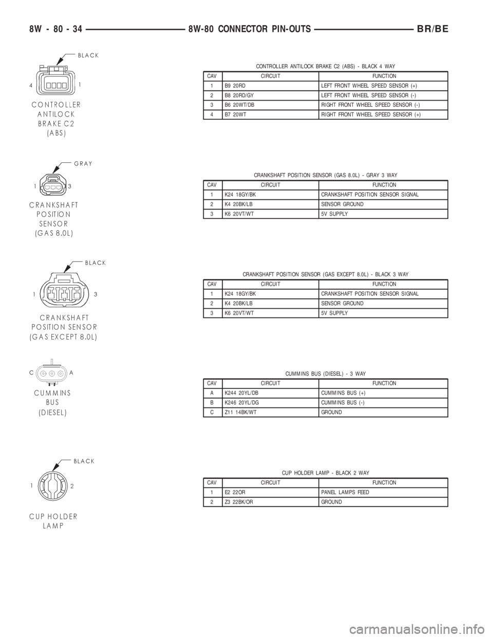
CONTROLLER ANTILOCK BRAKE C2 (ABS) - BLACK 4 WAY
CAV CIRCUIT FUNCTION
1 B9 20RD LEFT FRONT WHEEL SPEED SENSOR (+)
2 B8 20RD/GY LEFT FRONT WHEEL SPEED SENSOR (-)
3 B6 20WT/DB RIGHT FRONT WHEEL SPEED SENSOR (-)
4 B7 20WT RIGHT FRONT WHEEL SPEED SENSOR (+)
CRANKSHAFT POSITION SENSOR (GAS 8.0L) - GRAY 3 WAY
CAV CIRCUIT FUNCTION
1 K24 18GY/BK CRANKSHAFT POSITION SENSOR SIGNAL
2 K4 20BK/LB SENSOR GROUND
3 K6 20VT/WT 5V SUPPLY
CRANKSHAFT POSITION SENSOR (GAS EXCEPT 8.0L) - BLACK 3 WAY
CAV CIRCUIT FUNCTION
1 K24 18GY/BK CRANKSHAFT POSITION SENSOR SIGNAL
2 K4 20BK/LB SENSOR GROUND
3 K6 20VT/WT 5V SUPPLY
CUMMINS BUS (DIESEL)-3WAY
CAV CIRCUIT FUNCTION
A K244 20YL/DB CUMMINS BUS (+)
B K246 20YL/DG CUMMINS BUS (-)
C Z11 14BK/WT GROUND
CUP HOLDER LAMP - BLACK 2 WAY
CAV CIRCUIT FUNCTION
1 E2 22OR PANEL LAMPS FEED
2 Z3 22BK/OR GROUND
8W - 80 - 34 8W-80 CONNECTOR PIN-OUTSBR/BE
Page 1053 of 2889
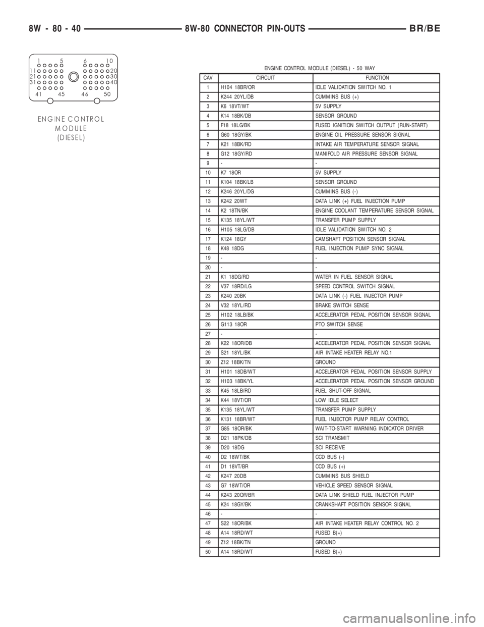
ENGINE CONTROL MODULE (DIESEL) - 50 WAY
CAV CIRCUIT FUNCTION
1 H104 18BR/OR IDLE VALIDATION SWITCH NO. 1
2 K244 20YL/DB CUMMINS BUS (+)
3 K6 18VT/WT 5V SUPPLY
4 K14 18BK/DB SENSOR GROUND
5 F18 18LG/BK FUSED IGNITION SWITCH OUTPUT (RUN-START)
6 G60 18GY/BK ENGINE OIL PRESSURE SENSOR SIGNAL
7 K21 18BK/RD INTAKE AIR TEMPERATURE SENSOR SIGNAL
8 G12 18GY/RD MANIFOLD AIR PRESSURE SENSOR SIGNAL
9- -
10 K7 18OR 5V SUPPLY
11 K104 18BK/LB SENSOR GROUND
12 K246 20YL/DG CUMMINS BUS (-)
13 K242 20WT DATA LINK (+) FUEL INJECTION PUMP
14 K2 18TN/BK ENGINE COOLANT TEMPERATURE SENSOR SIGNAL
15 K135 18YL/WT TRANSFER PUMP SUPPLY
16 H105 18LG/DB IDLE VALIDATION SWITCH NO. 2
17 K124 18GY CAMSHAFT POSITION SENSOR SIGNAL
18 K48 18DG FUEL INJECTION PUMP SYNC SIGNAL
19 - -
20 - -
21 K1 18DG/RD WATER IN FUEL SENSOR SIGNAL
22 V37 18RD/LG SPEED CONTROL SWITCH SIGNAL
23 K240 20BK DATA LINK (-) FUEL INJECTOR PUMP
24 V32 18YL/RD BRAKE SWITCH SENSE
25 H102 18LB/BK ACCELERATOR PEDAL POSITION SENSOR SIGNAL
26 G113 18OR PTO SWITCH SENSE
27 - -
28 K22 18OR/DB ACCELERATOR PEDAL POSITION SENSOR SIGNAL
29 S21 18YL/BK AIR INTAKE HEATER RELAY NO.1
30 Z12 18BK/TN GROUND
31 H101 18DB/WT ACCELERATOR PEDAL POSITION SENSOR SUPPLY
32 H103 18BK/YL ACCELERATOR PEDAL POSITION SENSOR GROUND
33 K45 18LB/RD FUEL SHUT-OFF SIGNAL
34 K44 18VT/OR LOW IDLE SELECT
35 K135 18YL/WT TRANSFER PUMP SUPPLY
36 K131 18BR/WT FUEL INJECTOR PUMP RELAY CONTROL
37 G85 18OR/BK WAIT-TO-START WARNING INDICATOR DRIVER
38 D21 18PK/DB SCI TRANSMIT
39 D20 18DG SCI RECEIVE
40 D2 18WT/BK CCD BUS (-)
41 D1 18VT/BR CCD BUS (+)
42 K247 20DB CUMMINS BUS SHIELD
43 G7 18WT/OR VEHICLE SPEED SENSOR SIGNAL
44 K243 20OR/BR DATA LINK SHIELD FUEL INJECTOR PUMP
45 K24 18GY/BK CRANKSHAFT POSITION SENSOR SIGNAL
46 - -
47 S22 18OR/BK AIR INTAKE HEATER RELAY CONTROL NO. 2
48 A14 18RD/WT FUSED B(+)
49 Z12 18BK/TN GROUND
50 A14 18RD/WT FUSED B(+)
8W - 80 - 40 8W-80 CONNECTOR PIN-OUTSBR/BE
Page 1094 of 2889
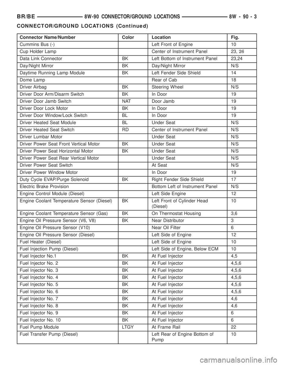
Connector Name/Number Color Location Fig.
Cummins Bus (-) Left Front of Engine 10
Cup Holder Lamp Center of Instrument Panel 23,26
Data Link Connector BK Left Bottom of Instrument Panel 23,24
Day/Night Mirror BK Day/Night Mirror N/S
Daytime Running Lamp Module BK Left Fender Side Shield 14
Dome Lamp Rear of Cab 18
Driver Airbag BK Steering Wheel N/S
Driver Door Arm/Disarm Switch BK In Door 19
Driver Door Jamb Switch NAT Door Jamb 19
Driver Door Lock Motor BK In Door 19
Driver Door Window/Lock Switch BL In Door 19
Driver Heated Seat Module BL Under Seat N/S
Driver Heated Seat Switch RD Center of Instrument Panel N/S
Driver Lumbar Motor Under Seat N/S
Driver Power Seat Front Vertical Motor BK Under Seat N/S
Driver Power Seat Horizontal Motor BK Under Seat N/S
Driver Power Seat Rear Vertical Motor Under Seat N/S
Driver Power Seat Switch At Seat N/S
Driver Power Window Motor In Door 19
Duty Cycle EVAP/Purge Solenoid BK Right Fender Side Shield 17
Electric Brake Provision Bottom Left of Instrument Panel N/S
Engine Control Module (Diesel) Left Side Engine 12
Engine Coolant Temperature Sensor (Diesel) BK Left Front of Cylinder Head
(Diesel)10
Engine Coolant Temperature Sensor (Gas) BK On Thermostat Housing 3,6
Engine Oil Pressure Sensor (V6, V8) BK Near Distributor 3
Engine Oil Pressure Sensor (V10) Near Oil Filter 6
Engine Oil Pressure Sensor (Diesel) Left Side of Engine 12
Fuel Heater (Diesel) Left Side of Engine 10
Fuel Injection Pump (Diesel) Left Side of Engine, Below ECM 10
Fuel Injector No.1 BK At Fuel Injector 4,5
Fuel Injector No. 2 BK At Fuel Injector 4,5,6
Fuel Injector No. 3 BK At Fuel Injector 4,5,6
Fuel Injector No. 4 BK At Fuel Injector 4,5,6
Fuel Injector No. 5 BK At Fuel Injector 4,5,6
Fuel Injector No. 6 BK At Fuel Injector 4,5,6
Fuel Injector No. 7 BK At Fuel Injector 4,6
Fuel Injector No. 8 BK At Fuel Injector 4,6
Fuel Injector No. 9 BK At Fuel Injector 6
Fuel Injector No. 10 BK At Fuel Injector 6
Fuel Pump Module LTGY At Frame Rail 22
Fuel Transfer Pump (Diesel) Left Rear of Engine Bottom of
Pump10
BR/BE8W-90 CONNECTOR/GROUND LOCATIONS 8W - 90 - 3
CONNECTOR/GROUND LOCATIONS (Continued)
Page 1378 of 2889
ENGINE 5.9L DIESEL
DESCRIPTION
The cylinder block is constructed of cast iron. The
casting is a skirted design which incorporates longi-
tudal ribs for superior strength and noise reduction.
The block incorporates metric straight thread o-ring
fittings at lubrication oil access points. The engine is
manufactured with the cylinders being a non-sleeved
type cylinder. However, one approved service method
is to bore out the cylinders and add cylinder sleeves
to the cylinder block.
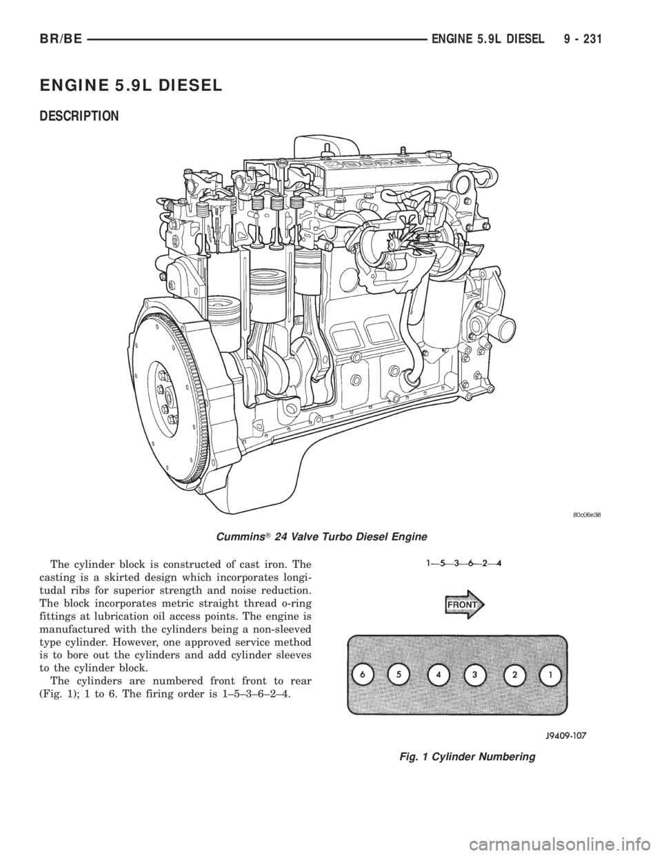
The cylinders are numbered front front to rear
(Fig. 1); 1 to 6. The firing order is 1±5±3±6±2±4.
CumminsT24 Valve Turbo Diesel Engine
Fig. 1 Cylinder Numbering
BR/BEENGINE 5.9L DIESEL 9 - 231
Page 1418 of 2889
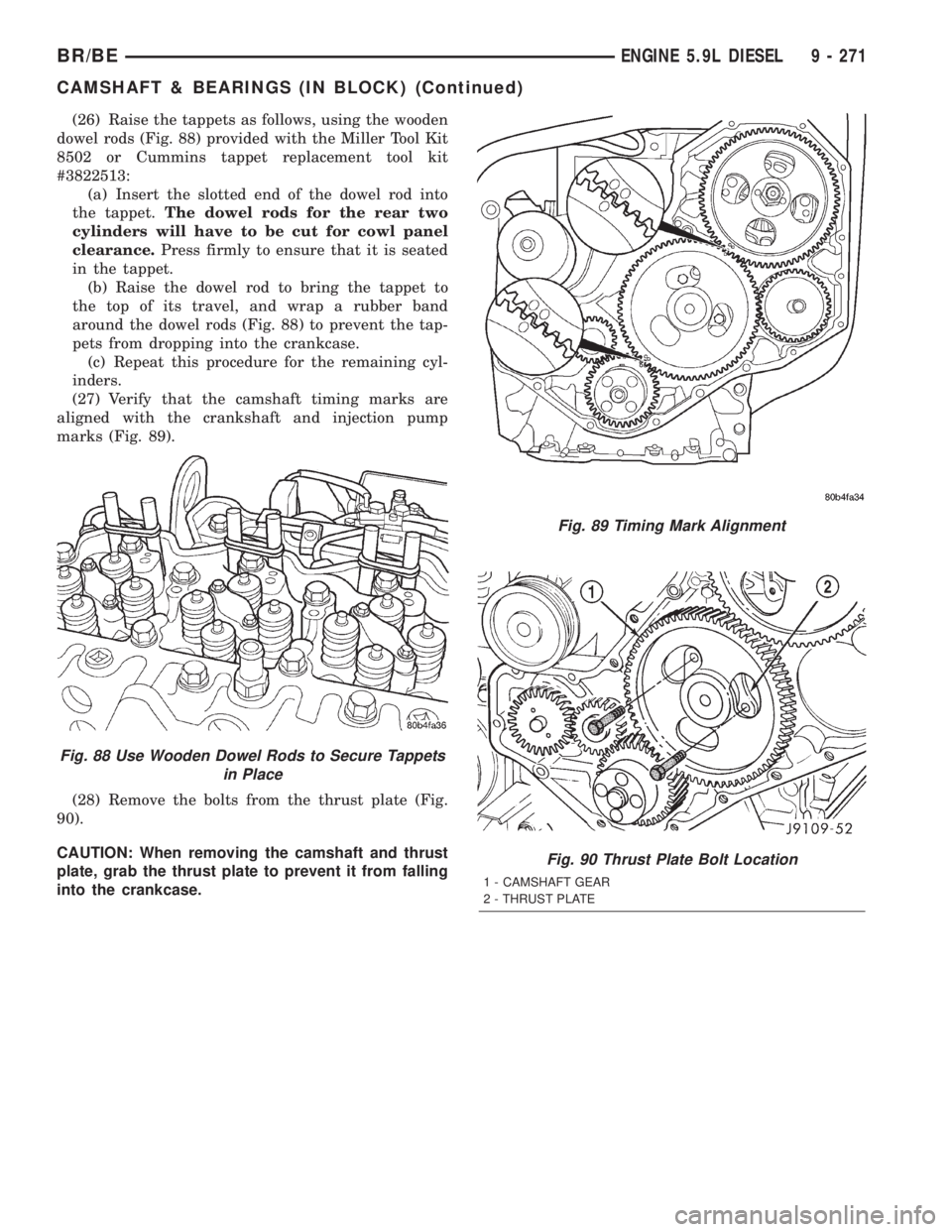
(26) Raise the tappets as follows, using the wooden
dowel rods (Fig. 88) provided with the Miller Tool Kit
8502 or Cummins tappet replacement tool kit
#3822513:
(a) Insert the slotted end of the dowel rod into
the tappet.The dowel rods for the rear two
cylinders will have to be cut for cowl panel
clearance.Press firmly to ensure that it is seated
in the tappet.
(b) Raise the dowel rod to bring the tappet to
the top of its travel, and wrap a rubber band
around the dowel rods (Fig. 88) to prevent the tap-
pets from dropping into the crankcase.
(c) Repeat this procedure for the remaining cyl-
inders.
(27) Verify that the camshaft timing marks are
aligned with the crankshaft and injection pump
marks (Fig. 89).
(28) Remove the bolts from the thrust plate (Fig.
90).
CAUTION: When removing the camshaft and thrust
plate, grab the thrust plate to prevent it from falling
into the crankcase.
Fig. 88 Use Wooden Dowel Rods to Secure Tappets
in Place
Fig. 89 Timing Mark Alignment
Fig. 90 Thrust Plate Bolt Location
1 - CAMSHAFT GEAR
2 - THRUST PLATE
BR/BEENGINE 5.9L DIESEL 9 - 271
CAMSHAFT & BEARINGS (IN BLOCK) (Continued)
Page 1427 of 2889
CAUTION: The seal lip and the sealing surface on
the crankshaft must be free from all oil residue to
prevent seal leaks. The crankshaft and seal sur-
faces must be completely dry when the seal is
installed. Use a soap and water solution on outside
diameter of seal to ease assembly.
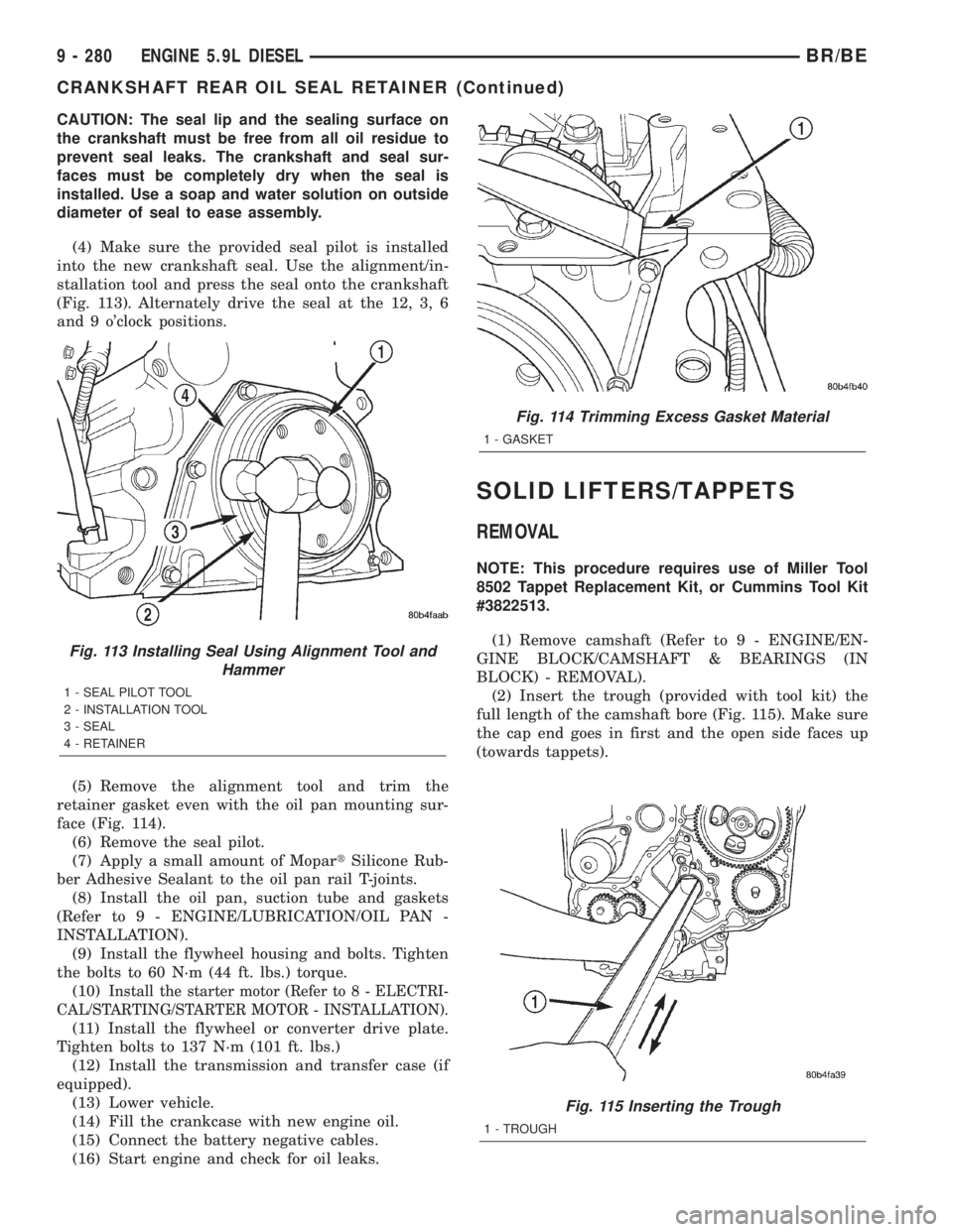
(4) Make sure the provided seal pilot is installed
into the new crankshaft seal. Use the alignment/in-
stallation tool and press the seal onto the crankshaft
(Fig. 113). Alternately drive the seal at the 12, 3, 6
and 9 o'clock positions.
(5) Remove the alignment tool and trim the
retainer gasket even with the oil pan mounting sur-
face (Fig. 114).
(6) Remove the seal pilot.
(7) Apply a small amount of MopartSilicone Rub-
ber Adhesive Sealant to the oil pan rail T-joints.
(8) Install the oil pan, suction tube and gaskets
(Refer to 9 - ENGINE/LUBRICATION/OIL PAN -
INSTALLATION).
(9) Install the flywheel housing and bolts. Tighten
the bolts to 60 N´m (44 ft. lbs.) torque.
(10)
Install the starter motor (Refer to 8 - ELECTRI-
CAL/STARTING/STARTER MOTOR - INSTALLATION).
(11) Install the flywheel or converter drive plate.
Tighten bolts to 137 N´m (101 ft. lbs.)
(12) Install the transmission and transfer case (if
equipped).
(13) Lower vehicle.
(14) Fill the crankcase with new engine oil.
(15) Connect the battery negative cables.
(16) Start engine and check for oil leaks.
SOLID LIFTERS/TAPPETS
REMOVAL
NOTE: This procedure requires use of Miller Tool
8502 Tappet Replacement Kit, or Cummins Tool Kit
#3822513.
(1) Remove camshaft (Refer to 9 - ENGINE/EN-
GINE BLOCK/CAMSHAFT & BEARINGS (IN
BLOCK) - REMOVAL).
(2) Insert the trough (provided with tool kit) the
full length of the camshaft bore (Fig. 115). Make sure
the cap end goes in first and the open side faces up
(towards tappets).
Fig. 115 Inserting the Trough
1 - TROUGH
Fig. 113 Installing Seal Using Alignment Tool and
Hammer
1 - SEAL PILOT TOOL
2 - INSTALLATION TOOL
3 - SEAL
4 - RETAINER
Fig. 114 Trimming Excess Gasket Material
1 - GASKET
9 - 280 ENGINE 5.9L DIESELBR/BE
CRANKSHAFT REAR OIL SEAL RETAINER (Continued)