2001 DODGE RAM interior
[x] Cancel search: interiorPage 2445 of 2889
CAUTION: Many of the valves and plugs, such as
the throttle valve, shuttle valve plug, 1-2 shift valve
and 1-2 governor plug, are made of coated alumi-
num. Aluminum components are identified by the
dark color of the special coating applied to the sur-
face (or by testing with a magnet). Do not sand alu-
minum valves or plugs under any circumstances.
This practice could damage the special coating
causing the valves/plugs to stick and bind.
Inspect the valves and plugs for scratches, burrs,
nicks, or scores. Minor surface scratches on steel
valves and plugs can be removed with crocus cloth
butdo not round off the edges of the valve or
plug lands.Maintaining sharpness of these edges is
vitally important. The edges prevent foreign matter
from lodging between the valves and plugs and the
bore.
Inspect all the valve and plug bores in the valve
body. Use a penlight to view the bore interiors.
Replace the valve body if any bores are distorted or
scored. Inspect all of the valve body springs. The
springs must be free of distortion, warpage or broken
coils.
Check the two separator plates for distortion or
damage of any kind. Inspect the upper housing,
lower housing, 3-4 accumulator housing, and transfer
plate carefully. Be sure all fluid passages are clean
and clear. Check condition of the upper housing andtransfer plate check balls as well. The check balls
and ball seats must not be worn or damaged.
Trial fit each valve and plug in its bore to check
freedom of operation. When clean and dry, the valves
and plugs should drop freely into the bores.
Valve body bores do not change dimensionally with
use. If the valve body functioned correctly when new,
it will continue to operate properly after cleaning and
inspection. It should not be necessary to replace a
valve body assembly unless it is damaged in han-
dling.
The only serviceable valve body components are
listed below. The remaining valve body components
are serviced only as part of a complete valve body
assembly. Serviceable parts are:
²dual solenoid and harness assembly
²solenoid gasket
²solenoid case connector O-rings and shoulder
bolt
²switch valve and spring
²pressure adjusting screw and bracket assembly
²throttle lever
²manual lever and shaft seal
²throttle lever shaft seal, washer, and E-clip
²fluid filter and screws
²detent ball and spring
²valve body screws
²governor pressure solenoid
²governor pressure sensor and retaining clip
²park lock rod and E-clip
ASSEMBLY
CAUTION: Do not force valves or plugs into place
during reassembly. If the valve body bores, valves
and plugs are free of distortion or burrs, the valve
body components should all slide into place easily.
In addition, do not overtighten the transfer plate
and valve body screws during reassembly. Over-
tightening can distort the housings resulting in
valve sticking, cross leakage and unsatisfactory
operation. Tighten valve body screws to recom-
mended torque only.
LOWER HOUSING
(1) Lubricate valves, springs, and the housing
valve and plug bores with clean transmission fluid
(Fig. 298).
(2) Install 3-4 timing valve spring and valve in
lower housing.
(3) Install 3-4 quick fill valve in lower housing.
(4) Install 3-4 quick fill valve spring and plug in
housing.
(5) Install timing valve end plate. Tighten end
plate screws to 4 N´m (35 in. lbs.) torque.
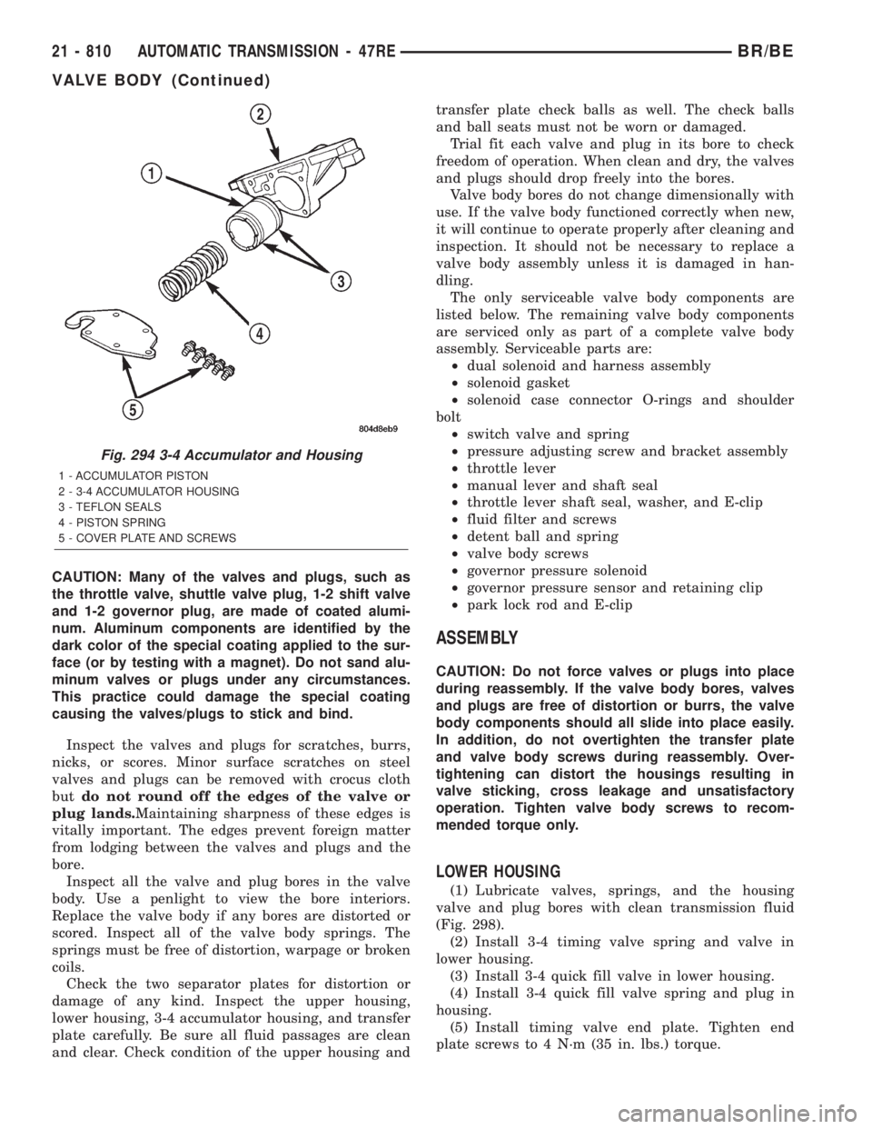
Fig. 294 3-4 Accumulator and Housing
1 - ACCUMULATOR PISTON
2 - 3-4 ACCUMULATOR HOUSING
3 - TEFLON SEALS
4 - PISTON SPRING
5 - COVER PLATE AND SCREWS
21 - 810 AUTOMATIC TRANSMISSION - 47REBR/BE
VALVE BODY (Continued)
Page 2467 of 2889
INSPECTION
MAINSHAFT/SPROCKET/HUB
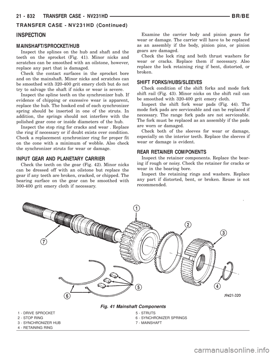
Inspect the splines on the hub and shaft and the
teeth on the sprocket (Fig. 41). Minor nicks and
scratches can be smoothed with an oilstone, however,
replace any part that is damaged.
Check the contact surfaces in the sprocket bore
and on the mainshaft. Minor nicks and scratches can
be smoothed with 320-400 grit emery cloth but do not
try to salvage the shaft if nicks or wear is severe.
Inspect the spline teeth on the synchronizer hub. If
evidence of chipping or excessive wear is apparent,
replace the hub. The hooked end of each synchronizer
spring should be inserted in one of the struts. In
addition, the springs should not interfere with the
polished gear cone or inside diameters of the hub.
Inspect the stop ring for cracks and wear . Replace
the ring if necessary or if doubt exists over condition.
Check a replacement synchronizer ring for proper fit
on the cone with a minimum of wobble. Also check
the synchronizer struts for wear or damage.
INPUT GEAR AND PLANETARY CARRIER
Check the teeth on the gear (Fig. 42). Minor nicks
can be dressed off with an oilstone but replace the
gear if any teeth are broken, cracked, or chipped. The
bearing surface on the gear can be smoothed with
300-400 grit emery cloth if necessary.Examine the carrier body and pinion gears for
wear or damage. The carrier will have to be replaced
as an assembly if the body, pinion pins, or pinion
gears are damaged.
Check the lock ring and both thrust washers for
wear or cracks. Replace them if necessary. Also
replace the lock retaining ring if bent, distorted, or
broken.
SHIFT FORKS/HUBS/SLEEVES
Check condition of the shift forks and mode fork
shift rail (Fig. 43). Minor nicks on the shift rail can
be smoothed with 320-400 grit emery cloth.
Inspect the shift fork wear pads (Fig. 44). The
mode fork pads are serviceable and can be replaced if
necessary. The range fork pads are not serviceable.
The fork must be replaced as an assembly if the pads
are worn or damaged.
Check both of the sleeves for wear or damage,
especially on the interior teeth. Replace the sleeves if
wear or damage is evident.
REAR RETAINER COMPONENTS
Inspect the retainer components. Replace the bear-
ing if rough or noisy. Check the retainer for cracks or
wear in the bearing bore.
Inspect the retaining rings and washers. Replace
any part if distorted, bent, or broken. Reuse is not
recommended.
Fig. 41 Mainshaft Components
1 - DRIVE SPROCKET 5 - STRUTS
2 - STOP RING 6 - SYNCHRONIZER SPRINGS
3 - SYNCHRONIZER HUB 7 - MAINSHAFT
4 - RETAINING RING
21 - 832 TRANSFER CASE - NV231HDBR/BE
TRANSFER CASE - NV231HD (Continued)
Page 2469 of 2889
LOW RANGE ANNULUS GEAR
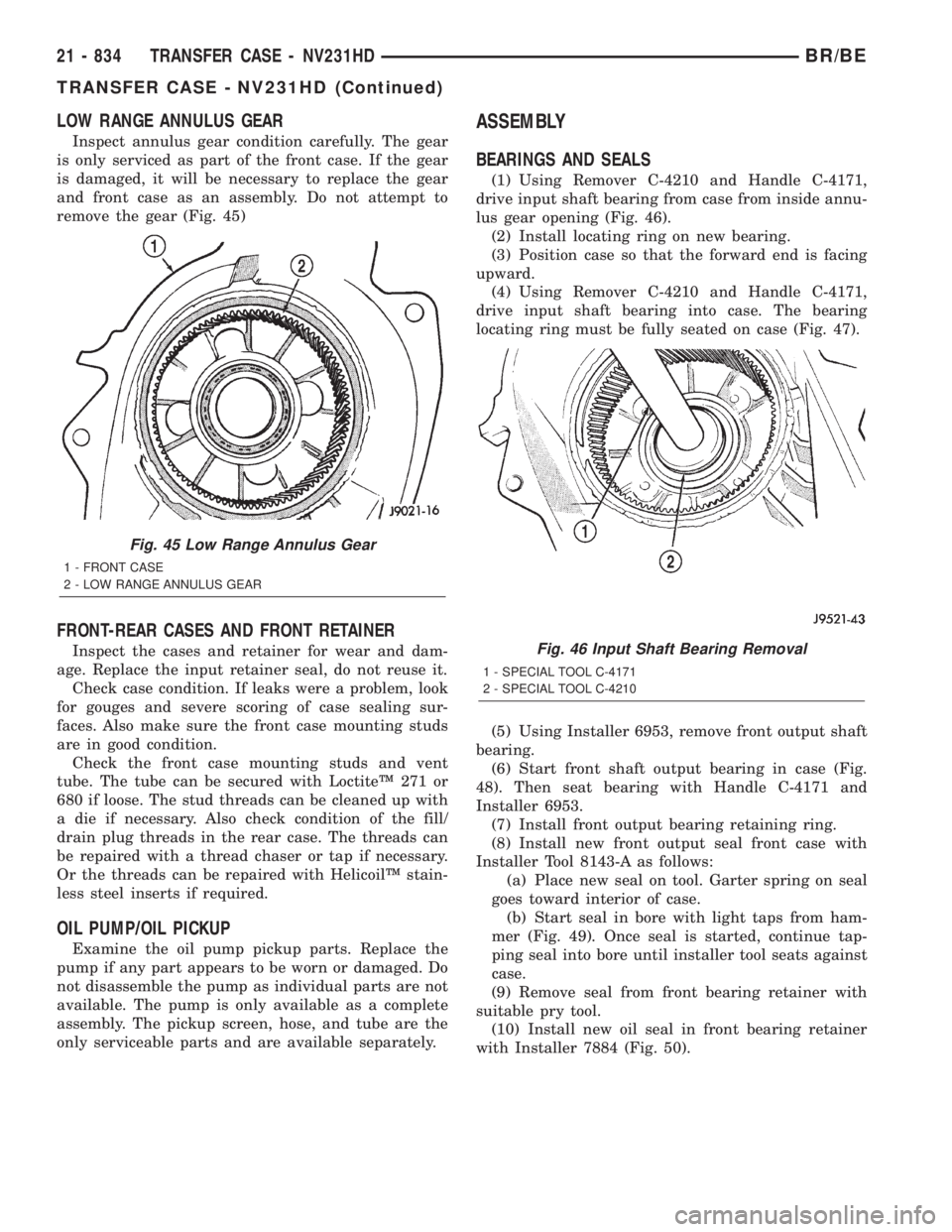
Inspect annulus gear condition carefully. The gear
is only serviced as part of the front case. If the gear
is damaged, it will be necessary to replace the gear
and front case as an assembly. Do not attempt to
remove the gear (Fig. 45)
FRONT-REAR CASES AND FRONT RETAINER
Inspect the cases and retainer for wear and dam-
age. Replace the input retainer seal, do not reuse it.
Check case condition. If leaks were a problem, look
for gouges and severe scoring of case sealing sur-
faces. Also make sure the front case mounting studs
are in good condition.
Check the front case mounting studs and vent
tube. The tube can be secured with LoctiteŸ 271 or
680 if loose. The stud threads can be cleaned up with
a die if necessary. Also check condition of the fill/
drain plug threads in the rear case. The threads can
be repaired with a thread chaser or tap if necessary.
Or the threads can be repaired with HelicoilŸ stain-
less steel inserts if required.
OIL PUMP/OIL PICKUP
Examine the oil pump pickup parts. Replace the
pump if any part appears to be worn or damaged. Do
not disassemble the pump as individual parts are not
available. The pump is only available as a complete
assembly. The pickup screen, hose, and tube are the
only serviceable parts and are available separately.
ASSEMBLY
BEARINGS AND SEALS
(1) Using Remover C-4210 and Handle C-4171,
drive input shaft bearing from case from inside annu-
lus gear opening (Fig. 46).
(2) Install locating ring on new bearing.
(3) Position case so that the forward end is facing
upward.
(4) Using Remover C-4210 and Handle C-4171,
drive input shaft bearing into case. The bearing
locating ring must be fully seated on case (Fig. 47).
(5) Using Installer 6953, remove front output shaft
bearing.
(6) Start front shaft output bearing in case (Fig.
48). Then seat bearing with Handle C-4171 and
Installer 6953.
(7) Install front output bearing retaining ring.
(8) Install new front output seal front case with
Installer Tool 8143-A as follows:
(a) Place new seal on tool. Garter spring on seal
goes toward interior of case.
(b) Start seal in bore with light taps from ham-
mer (Fig. 49). Once seal is started, continue tap-
ping seal into bore until installer tool seats against
case.
(9) Remove seal from front bearing retainer with
suitable pry tool.
(10) Install new oil seal in front bearing retainer
with Installer 7884 (Fig. 50).
Fig. 45 Low Range Annulus Gear
1 - FRONT CASE
2 - LOW RANGE ANNULUS GEAR
Fig. 46 Input Shaft Bearing Removal
1 - SPECIAL TOOL C-4171
2 - SPECIAL TOOL C-4210
21 - 834 TRANSFER CASE - NV231HDBR/BE
TRANSFER CASE - NV231HD (Continued)
Page 2479 of 2889
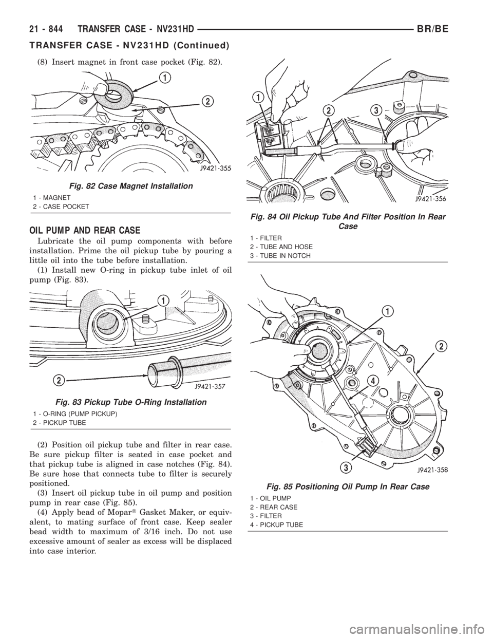
(8) Insert magnet in front case pocket (Fig. 82).
OIL PUMP AND REAR CASE
Lubricate the oil pump components with before
installation. Prime the oil pickup tube by pouring a
little oil into the tube before installation.
(1) Install new O-ring in pickup tube inlet of oil
pump (Fig. 83).
(2) Position oil pickup tube and filter in rear case.
Be sure pickup filter is seated in case pocket and
that pickup tube is aligned in case notches (Fig. 84).
Be sure hose that connects tube to filter is securely
positioned.
(3) Insert oil pickup tube in oil pump and position
pump in rear case (Fig. 85).
(4) Apply bead of MopartGasket Maker, or equiv-
alent, to mating surface of front case. Keep sealer
bead width to maximum of 3/16 inch. Do not use
excessive amount of sealer as excess will be displaced
into case interior.
Fig. 82 Case Magnet Installation
1 - MAGNET
2 - CASE POCKET
Fig. 83 Pickup Tube O-Ring Installation
1 - O-RING (PUMP PICKUP)
2 - PICKUP TUBE
Fig. 84 Oil Pickup Tube And Filter Position In Rear
Case
1 - FILTER
2 - TUBE AND HOSE
3 - TUBE IN NOTCH
Fig. 85 Positioning Oil Pump In Rear Case
1 - OIL PUMP
2 - REAR CASE
3 - FILTER
4 - PICKUP TUBE
21 - 844 TRANSFER CASE - NV231HDBR/BE
TRANSFER CASE - NV231HD (Continued)
Page 2487 of 2889
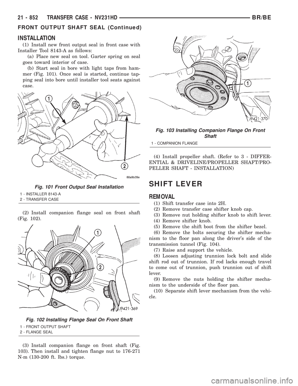
INSTALLATION
(1) Install new front output seal in front case with
Installer Tool 8143-A as follows:
(a) Place new seal on tool. Garter spring on seal
goes toward interior of case.
(b) Start seal in bore with light taps from ham-
mer (Fig. 101). Once seal is started, continue tap-
ping seal into bore until installer tool seats against
case.
(2) Install companion flange seal on front shaft
(Fig. 102).
(3) Install companion flange on front shaft (Fig.
103). Then install and tighten flange nut to 176-271
N´m (130-200 ft. lbs.) torque.(4) Install propeller shaft. (Refer to 3 - DIFFER-
ENTIAL & DRIVELINE/PROPELLER SHAFT/PRO-
PELLER SHAFT - INSTALLATION)
SHIFT LEVER
REMOVAL
(1) Shift transfer case into 2H.
(2) Remove transfer case shifter knob cap.
(3) Remove nut holding shifter knob to shift lever.
(4) Remove shifter knob.
(5) Remove the shift boot from the shifter bezel.
(6) Remove the bolts securing the shifter mecha-
nism to the floor pan along the driver's side of the
transmission tunnel (Fig. 104).
(7) Raise and support the vehicle.
(8) Loosen adjusting trunnion lock bolt and slide
shift rod out of trunnion. If rod lacks enough travel
to come out of trunnion, push trunnion out of shift
lever.
(9) Remove the nuts holding the shifter mecha-
nism to the underside of the floor pan.
(10) Separate shift lever mechanism from the vehi-
cle.
Fig. 101 Front Output Seal Installation
1 - INSTALLER 8143-A
2 - TRANSFER CASE
Fig. 102 Installing Flange Seal On Front Shaft
1 - FRONT OUTPUT SHAFT
2 - FLANGE SEAL
Fig. 103 Installing Companion Flange On Front
Shaft
1 - COMPANION FLANGE
21 - 852 TRANSFER CASE - NV231HDBR/BE
FRONT OUTPUT SHAFT SEAL (Continued)
Page 2503 of 2889
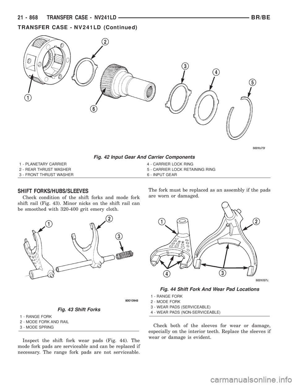
SHIFT FORKS/HUBS/SLEEVES
Check condition of the shift forks and mode fork
shift rail (Fig. 43). Minor nicks on the shift rail can
be smoothed with 320-400 grit emery cloth.
Inspect the shift fork wear pads (Fig. 44). The
mode fork pads are serviceable and can be replaced if
necessary. The range fork pads are not serviceable.The fork must be replaced as an assembly if the pads
are worn or damaged.
Check both of the sleeves for wear or damage,
especially on the interior teeth. Replace the sleeves if
wear or damage is evident.
Fig. 42 Input Gear And Carrier Components
1 - PLANETARY CARRIER 4 - CARRIER LOCK RING
2 - REAR THRUST WASHER 5 - CARRIER LOCK RETAINING RING
3 - FRONT THRUST WASHER 6 - INPUT GEAR
Fig. 43 Shift Forks
1 - RANGE FORK
2 - MODE FORK AND RAIL
3 - MODE SPRING
Fig. 44 Shift Fork And Wear Pad Locations
1 - RANGE FORK
2 - MODE FORK
3 - WEAR PADS (SERVICEABLE)
4 - WEAR PADS (NON-SERVICEABLE)
21 - 868 TRANSFER CASE - NV241LDBR/BE
TRANSFER CASE - NV241LD (Continued)
Page 2504 of 2889
REAR RETAINER COMPONENTS
Inspect the retainer components. Replace the bear-
ing if rough or noisy. Check the retainer for cracks or
wear in the bearing bore.
Inspect the retaining rings and washers. Replace
any part if distorted, bent, or broken. Reuse is not
recommended.
Inspect rear extension bushing. Replace if worn or
scored.
DRIVE CHAIN
Examine the drive chain and shaft bearings.
replace the chain if stretched, distorted, or if any of
the links bind. Replace the bearings if rough, or
noisy.
LOW RANGE ANNULUS GEAR
Inspect annulus gear condition carefully. The gear
is only serviced as part of the front case. If the gear
is damaged, it will be necessary to replace the gear
and front case as an assembly. Do not attempt to
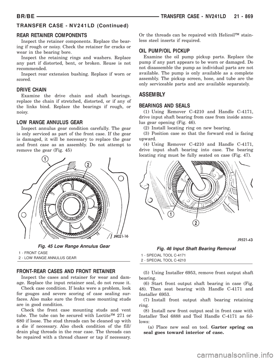
remove the gear (Fig. 45)
FRONT-REAR CASES AND FRONT RETAINER
Inspect the cases and retainer for wear and dam-
age. Replace the input retainer seal, do not reuse it.
Check case condition. If leaks were a problem, look
for gouges and severe scoring of case sealing sur-
faces. Also make sure the front case mounting studs
are in good condition.
Check the front case mounting studs and vent
tube. The tube can be secured with LoctiteŸ 271 or
680 if loose. The stud threads can be cleaned up with
a die if necessary. Also check condition of the fill/
drain plug threads in the rear case. The threads can
be repaired with a thread chaser or tap if necessary.Or the threads can be repaired with HelicoilŸ stain-
less steel inserts if required.
OIL PUMP/OIL PICKUP
Examine the oil pump pickup parts. Replace the
pump if any part appears to be worn or damaged. Do
not disassemble the pump as individual parts are not
available. The pump is only available as a complete
assembly. The pickup screen, hose, and tube are the
only serviceable parts and are available separately.
ASSEMBLY
BEARINGS AND SEALS
(1) Using Remover C-4210 and Handle C-4171,
drive input shaft bearing from case from inside annu-
lus gear opening (Fig. 46).
(2) Install locating ring on new bearing.
(3) Position case so that the forward end is facing
upward.
(4) Using Remover C-4210 and Handle C-4171,
drive input shaft bearing into case. The bearing
locating ring must be fully seated on case (Fig. 47).
(5) Using Installer 6953, remove front output shaft
bearing.
(6) Start front output shaft bearing in case (Fig.
48). Then seat bearing with Handle C-4171 and
Installer 6953.
(7) Install front output shaft bearing retaining
ring.
(8) Install new front output seal in front case with
Installer Tool 6888 and Tool Handle C-4171 as fol-
lows:
(a) Place new seal on tool.Garter spring on
seal goes toward interior of case.
Fig. 45 Low Range Annulus Gear
1 - FRONT CASE
2 - LOW RANGE ANNULUS GEARFig. 46 Input Shaft Bearing Removal
1 - SPECIAL TOOL C-4171
2 - SPECIAL TOOL C-4210
BR/BETRANSFER CASE - NV241LD 21 - 869
TRANSFER CASE - NV241LD (Continued)
Page 2515 of 2889
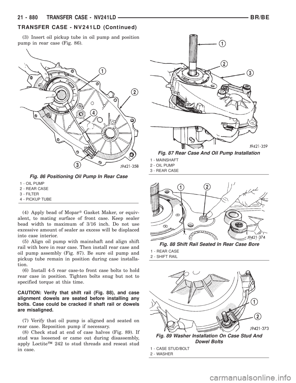
(3) Insert oil pickup tube in oil pump and position
pump in rear case (Fig. 86).
(4) Apply bead of MopartGasket Maker, or equiv-
alent, to mating surface of front case. Keep sealer
bead width to maximum of 3/16 inch. Do not use
excessive amount of sealer as excess will be displaced
into case interior.
(5) Align oil pump with mainshaft and align shift
rail with bore in rear case. Then install rear case and
oil pump assembly (Fig. 87). Be sure oil pump and
pickup tube remain in position during case installa-
tion.
(6) Install 4-5 rear case-to front case bolts to hold
rear case in position. Tighten bolts snug but not to
specified torque at this time.
CAUTION: Verify that shift rail (Fig. 88), and case
alignment dowels are seated before installing any
bolts. Case could be cracked if shaft rail or dowels
are misaligned.
(7) Verify that oil pump is aligned and seated on
rear case. Reposition pump if necessary.
(8) Check stud at end of case halves (Fig. 89). If
stud was loosened or came out during disassembly,
apply LoctiteŸ 242 to stud threads and reseat stud
in case.
Fig. 87 Rear Case And Oil Pump Installation
1 - MAINSHAFT
2 - OIL PUMP
3 - REAR CASE
Fig. 88 Shift Rail Seated In Rear Case Bore
1 - REAR CASE
2 - SHIFT RAIL
Fig. 89 Washer Installation On Case Stud And
Dowel Bolts
1 - CASE STUD/BOLT
2 - WASHER
Fig. 86 Positioning Oil Pump In Rear Case
1 - OIL PUMP
2 - REAR CASE
3 - FILTER
4 - PICKUP TUBE
21 - 880 TRANSFER CASE - NV241LDBR/BE
TRANSFER CASE - NV241LD (Continued)