2001 DODGE RAM interior
[x] Cancel search: interiorPage 633 of 2889
(5) Install the glove box onto the instrument panel.
(Refer to 23 - BODY/INSTRUMENT PANEL/GLOVE
BOX - INSTALLATION) for the procedures.
(6) Close the glove box.
(7) Reconnect the battery negative cable.
READING LAMP
DESCRIPTION
The overhead console in this vehicle is equipped
with two individual reading and courtesy lamps. The
lamp lenses are the only visible components of these
lamps. The reading and courtesy lamp lenses are
mounted in the overhead console housing between
the garage door opener storage bin and the sun-
glasses storage bin. Each lamp has its own switch,
bulb, reflector and lens; but both lamps share a com-
mon lamp housing within the overhead console.
The overhead console reading and courtesy lamps
operate on battery current that is provided at all
times, regardless of the ignition switch position. The
ground feed for the lamps is switched through the
integral reading and courtesy lamp switches or
through the door jamb switches. Each lamp is
designed and aimed to provide illumination that will
be directed only to that side of the vehicle on which
the lamp is located.
The reading and courtesy lamp lenses, bulbs and
the lamp housing and reflector unit are available for
service replacement. The reading and courtesy lamp
switches, bulb holders and wiring are only available
as part of the overhead console wire harness. If
either of the lamp switches or bulb holders is faulty
or damaged, the entire overhead console wire har-
ness assembly must be replaced.
For service of the reading and courtesy lamp bulbs,
refer to the appropriate wiring information. The wir-
ing information includes wiring diagrams, proper
wire and connector repair procedures, details of wire
harness routing and retention, connector pin-out
information and location views for the various wire
harness connectors, splices and grounds.
OPERATION
All reading and courtesy lamps located in the over-
head console are activated by the door jamb switches.
When all of the doors are closed, these lamps can be
individually activated by depressing the correspond-
ing lens. When any door is open, depressing the lamp
lenses to activate the lamp switches will not turn the
lamps off.
See the owner's manual in the vehicle glove box for
more information on the use and operation of the
overhead console reading and courtesy lamps.
REMOVAL
(1) Disconnect and isolate the battery negative
cable.
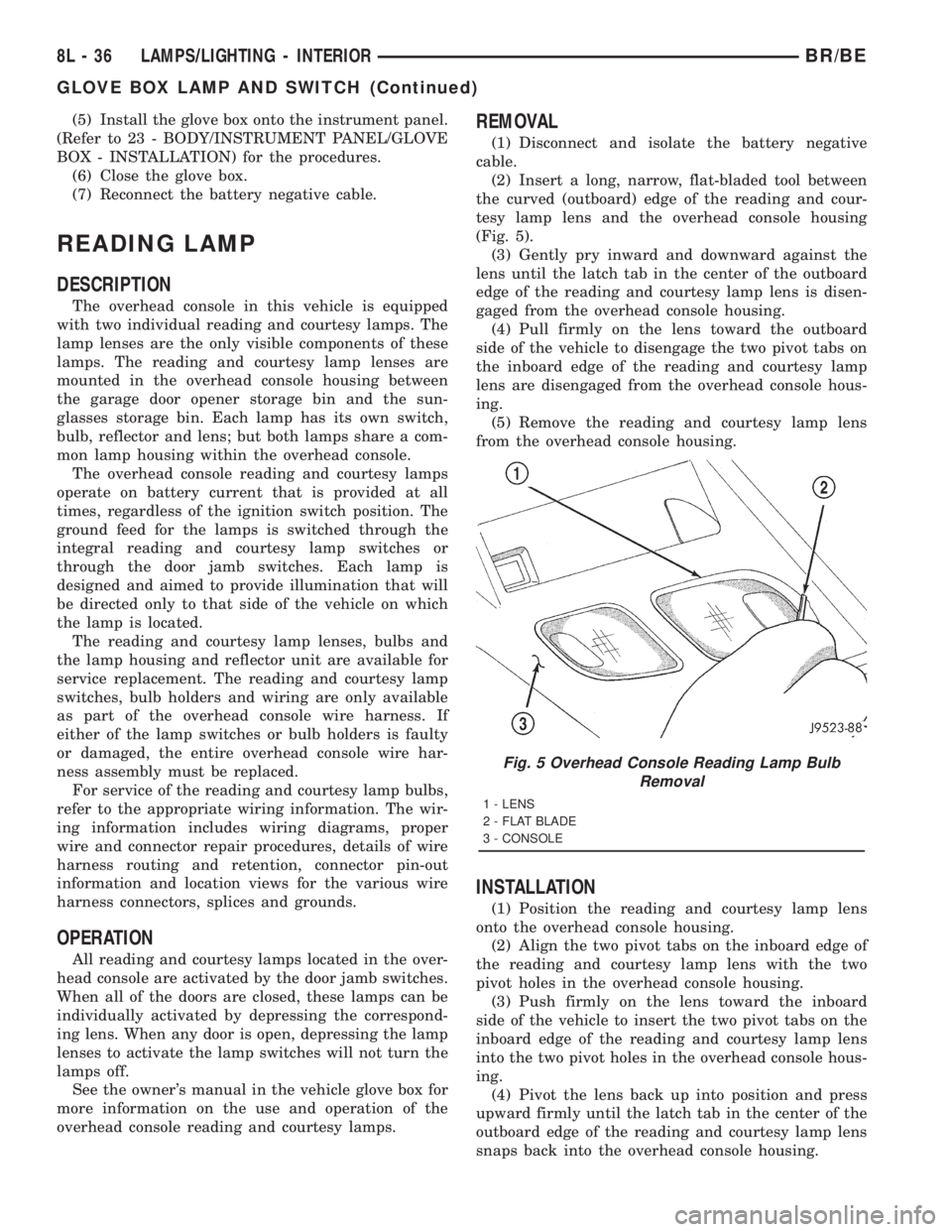
(2) Insert a long, narrow, flat-bladed tool between
the curved (outboard) edge of the reading and cour-
tesy lamp lens and the overhead console housing
(Fig. 5).
(3) Gently pry inward and downward against the
lens until the latch tab in the center of the outboard
edge of the reading and courtesy lamp lens is disen-
gaged from the overhead console housing.
(4) Pull firmly on the lens toward the outboard
side of the vehicle to disengage the two pivot tabs on
the inboard edge of the reading and courtesy lamp
lens are disengaged from the overhead console hous-
ing.
(5) Remove the reading and courtesy lamp lens
from the overhead console housing.
INSTALLATION
(1) Position the reading and courtesy lamp lens
onto the overhead console housing.
(2) Align the two pivot tabs on the inboard edge of
the reading and courtesy lamp lens with the two
pivot holes in the overhead console housing.
(3) Push firmly on the lens toward the inboard
side of the vehicle to insert the two pivot tabs on the
inboard edge of the reading and courtesy lamp lens
into the two pivot holes in the overhead console hous-
ing.
(4) Pivot the lens back up into position and press
upward firmly until the latch tab in the center of the
outboard edge of the reading and courtesy lamp lens
snaps back into the overhead console housing.
Fig. 5 Overhead Console Reading Lamp Bulb
Removal
1 - LENS
2 - FLAT BLADE
3 - CONSOLE
8L - 36 LAMPS/LIGHTING - INTERIORBR/BE
GLOVE BOX LAMP AND SWITCH (Continued)
Page 634 of 2889

(5) Reconnect the battery negative cable.
VANITY LAMP
REMOVAL
(1) Insert a flat blade into the slot at front of lens.
(2) Rotate blade until lens pops out of lamp.
(3) Remove lens from housing.(4) Remove bulb from lamp terminals.
INSTALLATION
(1) Install bulb into lamp terminals.
(2) Place one side of lens into housing.
(3) Insure dim control is in place, and snap lens
into housing.
BR/BELAMPS/LIGHTING - INTERIOR 8L - 37
READING LAMP (Continued)
Page 638 of 2889

With the transmitter mounted in the storage bin,
adapter pegs located on the garage door opener push
button unit are selected and mounted on one of two
posts on the back side of the push button. The com-
bination of the adapter peg length and the push but-
ton post location must be suitable to depress the
button of the transmitter when the push button in
the center of the garage door opener storage bin door
is depressed. When the proper combination has been
selected, the push button is reinstalled in the com-
partment and the compartment door is closed.
SUNGLASS STORAGE BIN
A sunglasses storage bin is included in the over-
head console. The storage bin is located near the rear
of the overhead console and is held in the closed posi-
tion by a latch that is integral to the storage bin
door. The interior of the bin is lined with a foam rub-
ber padding material to protect the sunglasses from
being scratched. Dampening springs that are located
on the back of the overhead console reading and
courtesy lamp housing contact the hinges of the sun-
glasses storage bin for a smooth opening action.
The sunglasses storage bin and door unit is avail-
able for service replacement. The hinge dampening
springs are serviced as a unit with the overhead con-
sole reading and courtesy lamp housing.
The sunglasses storage bin is opened by pressing
the latch on the rear edge of the door towards the
front of the vehicle, then pulling the bin downward to
the open position. The integral latch on the sun-
glasses bin door will automatically engage when the
bin is closed. See the owner's manual in the vehicle
glove box for more information on the use and oper-
ation of the sunglasses storage bin.
COMPASS
While in the compass/temperature mode, the com-
pass will display the direction in which the vehicle is
pointed using the eight major compass headings
(Examples: north is N, northeast is NE), along with
the outside ambient temperature. When the compass
unit is placed in the compass/compass in degreesmode, the compass will display the direction the
vehicle is heading using the eight major compass
headings and in degrees (0 to 359 degrees). North is
0 degrees, East is 90 degrees, South is 180 degrees
and West is 270 degrees. It will not display the head-
ings in minutes or seconds.
The self-calibrating compass unit requires no
adjusting in normal use. The compass unit will com-
pensate for magnetism the body of the vehicle may
acquire during normal use. However, avoid placing
anything magnetic directly on the roof of the vehicle.
Magnetic mounts for an antenna, a repair order hat,
or a funeral procession flag can exceed the compen
sating ability of the compass unit if placed on the
roof panel. If the vehicle roof should become magne-
tized, the demagnetizing and calibration procedures
found in this group may be required to restore proper
compass operation.
THERMOMETER
The thermometer displays the outside ambient
temperature in whole degrees. The temperature dis-
play can be changed from Fahrenheit to Celsius
using the U.S./Metric push button. The displayed
temperature is not an instant reading of conditions,
but an average temperature. It may take the ther-
mometer display several minutes to respond to a
major temperature change, such as driving out of a
heated garage into winter temperatures.
When the ignition switch is turned to the Off posi-
tion, the last displayed temperature reading stays in
the thermometer unit memory. When the ignition
switch is turned to the On position again, the ther-
mometer will display the memory temperature if the
engine coolant temperature is above about 43É C
(109É F). If the engine coolant temperature is below
about 43É C (109É F), the thermometer will display
the actual temperature sensed by the ambient tem-
perature sensor. The thermometer temperature dis-
play update interval varies with the vehicle speed;
therefore, if the temperature reading seems inaccu-
rate, drive the vehicle for at least three minutes
1 - SUNGLASSES STORAGE BIN
2 - GARAGE DOOR OPENER STORAGE BIN DOOR
3 - COMPUTER LENS OR COVER PLUG
4 - HOOK AND LOOP FASTENER
5 - SECURITY INDICATOR LAMP
6 - COMPASS MINI-TRIP COMPUTER MODULE
7 - SCREW (3)
8 - SCREW (4)
9 - BULB HOLDERS
10 - SWITCHES11 - WIRE HARNESS
12 - SPRINGS (2)
13 - READING AND COURTESY LAMP HOUSING
14 - REFLECTORS
15 - OVERHEAD CONSOLE HOUSING
16 - LENSES
17 - BUMPER
18 - GARAGE DOOR OPENER PUSH BUTTON
BR/BEMESSAGE SYSTEMS 8M - 3
OVERHEAD CONSOLE (Continued)
Page 680 of 2889
WARNING: IF YOU EXPERIENCE SKIN IRRITATION
DURING CLEANUP, RUN COOL WATER OVER THE
AFFECTED AREA. ALSO, IF YOU EXPERIENCE
IRRITATION OF THE NOSE OR THROAT, EXIT THE
VEHICLE FOR FRESH AIR UNTIL THE IRRITATION
CEASES. IF IRRITATION CONTINUES, SEE A PHYSI-
CIAN.
Begin the cleanup by removing both airbags from
the vehicle. Refer to the appropriate service removal
procedures. Place the deployed airbags in your vehic-
ular scrap pile.
Next, use a vacuum cleaner to remove any residual
powder from the vehicle interior. Clean from outside
the vehicle and work your way inside, so that you
avoid kneeling or sitting on a non-cleaned area. Be
certain to vacuum the heater and air conditioning
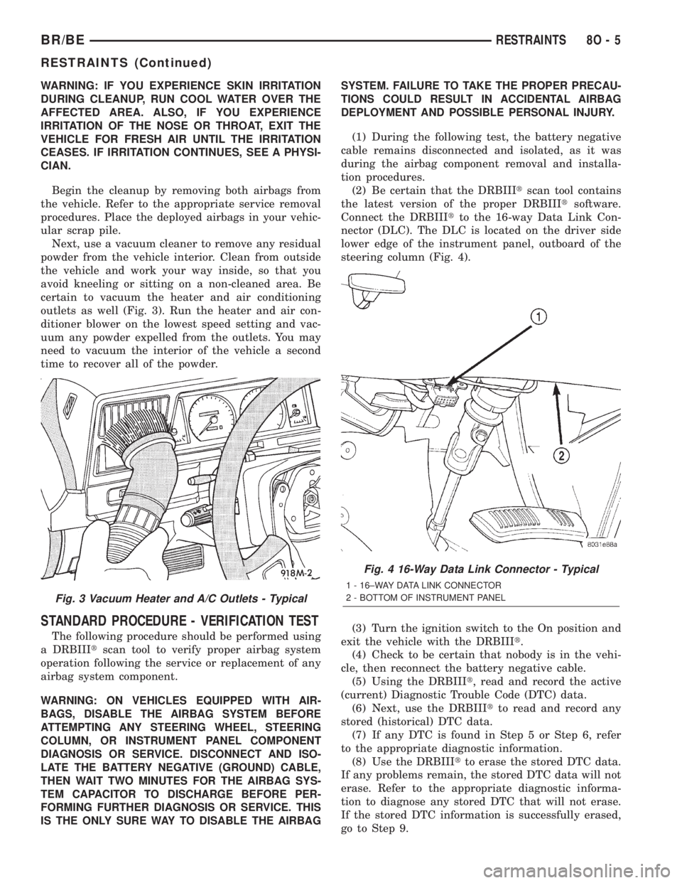
outlets as well (Fig. 3). Run the heater and air con-
ditioner blower on the lowest speed setting and vac-
uum any powder expelled from the outlets. You may
need to vacuum the interior of the vehicle a second
time to recover all of the powder.
STANDARD PROCEDURE - VERIFICATION TEST
The following procedure should be performed using
a DRBIIItscan tool to verify proper airbag system
operation following the service or replacement of any
airbag system component.
WARNING: ON VEHICLES EQUIPPED WITH AIR-
BAGS, DISABLE THE AIRBAG SYSTEM BEFORE
ATTEMPTING ANY STEERING WHEEL, STEERING
COLUMN, OR INSTRUMENT PANEL COMPONENT
DIAGNOSIS OR SERVICE. DISCONNECT AND ISO-
LATE THE BATTERY NEGATIVE (GROUND) CABLE,
THEN WAIT TWO MINUTES FOR THE AIRBAG SYS-
TEM CAPACITOR TO DISCHARGE BEFORE PER-
FORMING FURTHER DIAGNOSIS OR SERVICE. THIS
IS THE ONLY SURE WAY TO DISABLE THE AIRBAGSYSTEM. FAILURE TO TAKE THE PROPER PRECAU-
TIONS COULD RESULT IN ACCIDENTAL AIRBAG
DEPLOYMENT AND POSSIBLE PERSONAL INJURY.
(1) During the following test, the battery negative
cable remains disconnected and isolated, as it was
during the airbag component removal and installa-
tion procedures.
(2) Be certain that the DRBIIItscan tool contains
the latest version of the proper DRBIIItsoftware.
Connect the DRBIIItto the 16-way Data Link Con-
nector (DLC). The DLC is located on the driver side
lower edge of the instrument panel, outboard of the
steering column (Fig. 4).
(3) Turn the ignition switch to the On position and
exit the vehicle with the DRBIIIt.
(4) Check to be certain that nobody is in the vehi-
cle, then reconnect the battery negative cable.
(5) Using the DRBIIIt, read and record the active
(current) Diagnostic Trouble Code (DTC) data.
(6) Next, use the DRBIIItto read and record any
stored (historical) DTC data.
(7) If any DTC is found in Step 5 or Step 6, refer
to the appropriate diagnostic information.
(8) Use the DRBIIItto erase the stored DTC data.
If any problems remain, the stored DTC data will not
erase. Refer to the appropriate diagnostic informa-
tion to diagnose any stored DTC that will not erase.
If the stored DTC information is successfully erased,
go to Step 9.
Fig. 3 Vacuum Heater and A/C Outlets - Typical
Fig. 4 16-Way Data Link Connector - Typical
1 - 16±WAY DATA LINK CONNECTOR
2 - BOTTOM OF INSTRUMENT PANEL
BR/BERESTRAINTS 8O - 5
RESTRAINTS (Continued)
Page 682 of 2889

the need for an airbag deployment by detecting
impact energy of a lesser magnitude than that of the
electronic impact sensor, and must be closed in order
for the airbags to deploy. The impact sensor and saf-
ing sensor are calibrated for the specific vehicle, and
are only serviced as a unit with the ACM.
REMOVAL
WARNING: DISABLE THE AIRBAG SYSTEM
BEFORE ATTEMPTING ANY STEERING WHEEL,
STEERING COLUMN, OR INSTRUMENT PANEL
COMPONENT DIAGNOSIS OR SERVICE. DISCON-
NECT AND ISOLATE THE BATTERY NEGATIVE
(GROUND) CABLE, THEN WAIT TWO MINUTES FOR
THE AIRBAG SYSTEM CAPACITOR TO DISCHARGE
BEFORE PERFORMING FURTHER DIAGNOSIS OR
SERVICE. THIS IS THE ONLY SURE WAY TO DIS-
ABLE THE AIRBAG SYSTEM. FAILURE TO TAKE
THE PROPER PRECAUTIONS COULD RESULT IN
ACCIDENTAL AIRBAG DEPLOYMENT AND POSSI-
BLE PERSONAL INJURY.
WARNING: THE AIRBAG CONTROL MODULE CON-
TAINS THE IMPACT SENSOR, WHICH ENABLES
THE SYSTEM TO DEPLOY THE AIRBAGS. NEVER
STRIKE OR KICK THE AIRBAG CONTROL MODULE,
AS IT CAN DAMAGE THE IMPACT SENSOR OR
AFFECT ITS CALIBRATION. IF AN AIRBAG CON-
TROL MODULE IS ACCIDENTALLY DROPPED DUR-
ING SERVICE, THE MODULE MUST BE SCRAPPED
AND REPLACED WITH A NEW UNIT. FAILURE TO
OBSERVE THIS WARNING COULD RESULT IN ACCI-
DENTAL, INCOMPLETE, OR IMPROPER AIRBAG
DEPLOYMENT AND POSSIBLE OCCUPANT INJU-
RIES.
(1) Disconnect and isolate the battery negative
cable. If either of the airbags has not been deployed,
wait two minutes for the system capacitor to dis-
charge before further service.
(2) If the vehicle is equipped with a manual trans-
mission, remove the center floor console from the
floor panel transmission tunnel. (Refer to 23 - BODY/
INTERIOR/CENTER CONSOLE - REMOVAL).
(3) If the vehicle is equipped with an automatic
transmission, remove the two screws that secure the
trim cover to the Airbag Control Module (ACM)
mounting bracket on the floor panel transmission
tunnel and remove the trim cover (Fig. 5).
(4) Loosen the screw that secures each side of the
instrument panel center support bracket to the ACM
mounting bracket (Fig. 6). Do not remove these
screws.
(5) Remove the two nuts that secure the instru-
ment panel center support bracket to the studs on
the lower instrument panel structural support.
Fig. 5 Airbag Control Module Trim Cover Remove/
Install
1 - INSTRUMENT PANEL CENTER SUPPORT BRACKET
2 - ACM MOUNTING BRACKET
3 - TRIM COVER
4 - SCREW (2)
Fig. 6 Airbag Control Module Remove/Install
1 - INSTRUMENT PANEL
2 - CENTER SUPPORT BRACKET
3 - SCREW (2)
4 - FLOOR PANEL
5 - SCREW (4)
6 - ACM MOUNTING BRACKET
7 - CONNECTOR
8 - AIRBAG CONTROL MODULE
9 - RETAINER
10 - NUT (2)
BR/BERESTRAINTS 8O - 7
AIRBAG CONTROL MODULE (Continued)
Page 683 of 2889

(6) Disengage the retainer on the instrument
panel wire harness take out to the ACM from the
retainer hole in the left side of the instrument panel
center support bracket.
(7) Pull the top of the instrument panel center
support bracket rearward and down from the instru-
ment panel studs. Fold it down over the top of the
ACM until it is laying flat on the floor panel trans-
mission tunnel.
(8) Disconnect the instrument panel wire harness
connector for the ACM from the ACM connector
receptacle. To disconnect this connector:
(a) Slide the red Connector Position Assurance
(CPA) lock on the top of the connector toward the
side of the vehicle.
(b) Depress the connector latch tab and pull the
connector straight away from the ACM connector
receptacle.
NOTE: Always remove and replace the ACM and its
mounting bracket as a unit. Replacement modules
include a replacement mounting bracket. Do not
transfer the ACM to another mounting bracket.
(9) Remove the four screws that secure the ACM
mounting bracket to the floor panel transmission
tunnel.
(10) Remove the ACM, the mounting bracket, and
the instrument panel center support bracket from the
floor panel transmission tunnel as a unit.
INSTALLATION
WARNING: DISABLE THE AIRBAG SYSTEM
BEFORE ATTEMPTING ANY STEERING WHEEL,
STEERING COLUMN, OR INSTRUMENT PANEL
COMPONENT DIAGNOSIS OR SERVICE. DISCON-
NECT AND ISOLATE THE BATTERY NEGATIVE
(GROUND) CABLE, THEN WAIT TWO MINUTES FOR
THE AIRBAG SYSTEM CAPACITOR TO DISCHARGE
BEFORE PERFORMING FURTHER DIAGNOSIS OR
SERVICE. THIS IS THE ONLY SURE WAY TO DIS-
ABLE THE AIRBAG SYSTEM. FAILURE TO TAKE
THE PROPER PRECAUTIONS COULD RESULT IN
ACCIDENTAL AIRBAG DEPLOYMENT AND POSSI-
BLE PERSONAL INJURY.
WARNING: THE AIRBAG CONTROL MODULE CON-
TAINS THE IMPACT SENSOR, WHICH ENABLES
THE SYSTEM TO DEPLOY THE AIRBAGS. NEVER
STRIKE OR KICK THE AIRBAG CONTROL MODULE,
AS IT CAN DAMAGE THE IMPACT SENSOR OR
AFFECT ITS CALIBRATION. IF AN AIRBAG CON-
TROL MODULE IS ACCIDENTALLY DROPPED DUR-
ING SERVICE, THE MODULE MUST BE SCRAPPED
AND REPLACED WITH A NEW UNIT. FAILURE TOOBSERVE THIS WARNING COULD RESULT IN ACCI-
DENTAL, INCOMPLETE, OR IMPROPER AIRBAG
DEPLOYMENT AND POSSIBLE OCCUPANT INJU-
RIES.
(1) Carefully position the Airbag Control Module
(ACM), the mounting bracket, and the instrument
panel center support bracket onto the floor panel
transmission tunnel as a unit (Fig. 6). When the
ACM is correctly positioned, the arrow on the ACM
label will be pointed forward in the vehicle.
(2) Install and tighten the four screws that secure
the ACM mounting bracket to the floor panel trans-
mission tunnel. Tighten the screws to 14 N´m (125
in. lbs.).
(3) With the instrument panel center support
bracket still folded down flat on the floor panel trans-
mission tunnel, reconnect the instrument panel wire
harness connector for the ACM to the ACM connector
receptacle. Be certain that the connector latch and
the red Connector Position Assurance (CPA) lock are
fully engaged.
(4) Fold the top of the instrument panel center
support bracket up over the top of the ACM and for-
ward over the studs on the lower instrument panel
structural support.
(5) Install and tighten the nuts that secure the
instrument panel center support bracket to the studs
on the lower instrument panel structural support.
Tighten the nuts to 14 N´m (125 in. lbs.).
(6) Engage the retainer on the instrument panel
wire harness take out for the ACM in the retainer
hole on the left side of the instrument panel center
support bracket.
(7) Tighten the screws that secure each side of the
instrument panel center support bracket to the ACM
mounting bracket. Tighten the screws 14 N´m (125
in. lbs.).
(8) If the vehicle is equipped with an automatic
transmission, position the ACM trim cover to the
ACM mounting bracket on the floor panel transmis-
sion tunnel (Fig. 5).
(9) If the vehicle is equipped with an automatic
transmission, install and tighten the two screws that
secure the ACM trim cover to the ACM mounting
bracket. Tighten the screws to 2.2 N´m (20 in. lbs.).
(10) If the vehicle is equipped with a manual
transmission, reinstall the center floor console onto
the floor panel transmission tunnel. (Refer to 23 -
BODY/INTERIOR/CENTER CONSOLE - INSTALLA-
TION).
(11) Do not reconnect the battery negative cable at
this time. The airbag system verification test proce-
dure should be performed following service of any
airbag system component. (Refer to 8 - ELECTRI-
CAL/RESTRAINTS - STANDARD PROCEDURE -
VERIFICATION TEST).
8O - 8 RESTRAINTSBR/BE
AIRBAG CONTROL MODULE (Continued)
Page 684 of 2889
CHILD TETHER
REMOVAL
Standard cab models have two child tether anchors
secured near the top of the cab back panel. Club cab
and quad cab models have three child tethers
secured near the top of the cab back panel.
WARNING: DURING AND FOLLOWING ANY SEAT
BELT SERVICE, CAREFULLY INSPECT ALL SEAT
BELTS, BUCKLES, MOUNTING HARDWARE, AND
RETRACTORS FOR PROPER INSTALLATION,
OPERATION, OR DAMAGE. REPLACE ANY BELT
THAT IS CUT, FRAYED, OR TORN. STRAIGHTEN
ANY BELT THAT IS TWISTED. TIGHTEN ANY
LOOSE FASTENERS. REPLACE ANY BELT THAT
HAS A DAMAGED OR INOPERATIVE BUCKLE OR
RETRACTOR. REPLACE ANY BELT THAT HAS A
BENT OR DAMAGED LATCH PLATE OR ANCHOR
PLATE. NEVER ATTEMPT TO REPAIR A SEAT BELT
COMPONENT. ALWAYS REPLACE DAMAGED OR
FAULTY SEAT BELT COMPONENTS WITH THE COR-
RECT, NEW AND UNUSED REPLACEMENT PARTS
LISTED IN THE MOPAR PARTS CATALOG.
(1) Remove the trim from the inside of the cab
back panel. (Refer to 23 - BODY/INTERIOR/REAR
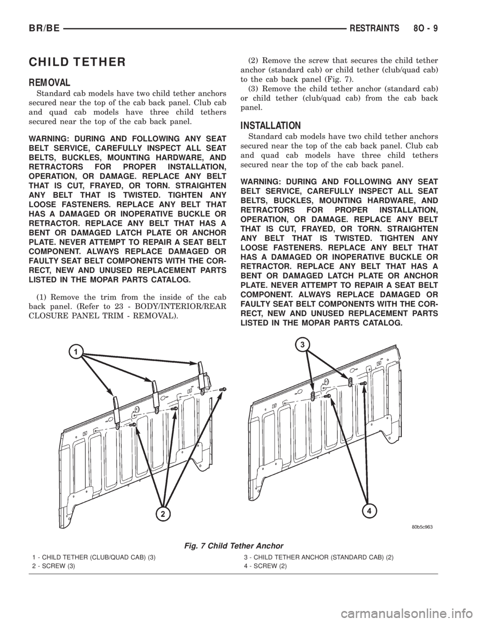
CLOSURE PANEL TRIM - REMOVAL).(2) Remove the screw that secures the child tether
anchor (standard cab) or child tether (club/quad cab)
to the cab back panel (Fig. 7).
(3) Remove the child tether anchor (standard cab)
or child tether (club/quad cab) from the cab back
panel.
INSTALLATION
Standard cab models have two child tether anchors
secured near the top of the cab back panel. Club cab
and quad cab models have three child tethers
secured near the top of the cab back panel.
WARNING: DURING AND FOLLOWING ANY SEAT
BELT SERVICE, CAREFULLY INSPECT ALL SEAT
BELTS, BUCKLES, MOUNTING HARDWARE, AND
RETRACTORS FOR PROPER INSTALLATION,
OPERATION, OR DAMAGE. REPLACE ANY BELT
THAT IS CUT, FRAYED, OR TORN. STRAIGHTEN
ANY BELT THAT IS TWISTED. TIGHTEN ANY
LOOSE FASTENERS. REPLACE ANY BELT THAT
HAS A DAMAGED OR INOPERATIVE BUCKLE OR
RETRACTOR. REPLACE ANY BELT THAT HAS A
BENT OR DAMAGED LATCH PLATE OR ANCHOR
PLATE. NEVER ATTEMPT TO REPAIR A SEAT BELT
COMPONENT. ALWAYS REPLACE DAMAGED OR
FAULTY SEAT BELT COMPONENTS WITH THE COR-
RECT, NEW AND UNUSED REPLACEMENT PARTS
LISTED IN THE MOPAR PARTS CATALOG.
Fig. 7 Child Tether Anchor
1 - CHILD TETHER (CLUB/QUAD CAB) (3)
2 - SCREW (3)3 - CHILD TETHER ANCHOR (STANDARD CAB) (2)
4 - SCREW (2)
BR/BERESTRAINTS 8O - 9
Page 685 of 2889

(1) Position the child tether anchor (standard cab)
or child tether (club/quad cab) onto the cab back
panel (Fig. 7).
(2) Install and tighten the screw that secures the
child tether anchor (standard cab) or child tether
(club/quad cab) onto the cab back panel. Tighten the
screw to 13.5 N´m (120 in. lbs.).
(3) Reinstall the trim onto the inside of the cab
back panel. (Refer to 23 - BODY/INTERIOR/REAR
CLOSURE PANEL TRIM - INSTALLATION).
CLOCKSPRING
DESCRIPTION
The clockspring assembly is secured with two inte-
gral plastic latches onto the steering column lock
housing near the top of the steering column, behind
the steering wheel. The clockspring consists of a flat,
round molded plastic case with a stubby tail that
hangs below the steering column and contains a con-
nector receptacle and a long pigtail wire with connec-
tor that face toward the instrument panel. Within
the plastic housing is a spool-like molded plastic
rotor with a large exposed hub. The upper surface of
the rotor hub has a large center hole, two large flats,
two auto-locking tabs, and three short pigtail wires
with connectors that face toward the steering wheel.
The lower surface of the rotor hub has two integral
turn signal cancelling cam lobes. Within the plastic
case and wound around the rotor spool is a long rib-
bon-like tape that consists of several thin copper wire
leads sandwiched between two thin plastic mem-
branes. The outer end of the tape terminates at the
connector receptacle and pigtail wire that face the
instrument panel, while the inner end of the tape
terminates at the pigtail wires on the hub of the
clockspring rotor that face the steering wheel.
Service replacement clocksprings are shipped pre-
centered and with a piece of tape covering the
engaged auto-locking tabs. The auto-locking tabs
secure the centered clockspring rotor to the clock-
spring case during shipment, but these tabs are auto-
matically disengaged once the clockspring is installed
on the steering column. (Refer to 8 - ELECTRICAL/
RESTRAINTS/CLOCKSPRING - STANDARD PRO-
CEDURE - CLOCKSPRING CENTERING).
The clockspring cannot be repaired. If the clock-
spring is faulty, damaged, or if the driver airbag has
been deployed, the clockspring must be replaced.
OPERATION
The clockspring is a mechanical electrical circuit
component that is used to provide continuous electri-
cal continuity between the fixed instrument panel
wire harness and the electrical components mountedon or in the rotating steering wheel. On this model
the rotating electrical components include the driver
airbag, the horn switch, the speed control switches,
and the remote radio switches if the vehicle is so
equipped. The clockspring case is positioned and
secured to the upper steering column lock housing by
two integral plastic latches. The connector receptacle
on the tail of the fixed clockspring housing connect
the clockspring to the vehicle electrical system
through a take out with connector from the instru-
ment panel wire harness. The lower clockspring pig-
tail on the tail of the clockspring housing connect the
clockspring driver airbag circuits to a separate take
out and connector of the instrument panel wire har-
ness located near the lower instrument panel rein-
forcement, below the steering column. The
clockspring rotor is movable and is keyed to the hub
of the steering wheel by two large flats that are
molded into the rotor hub. The two lobes on the
lower surface of the clockspring rotor hub contact a
turn signal cancel actuator of the multi-function
switch to provide automatic turn signal cancellation.
The pigtail wires on the upper surface of the clock-
spring connect the clockspring to the horn switch, the
two speed control switches, and the remote radio
switches on vehicles that are so equipped.
Like the clockspring in a timepiece, the clockspring
tape has travel limits and can be damaged by being
wound too tightly during full stop-to-stop steering
wheel rotation. To prevent this from occurring, the
clockspring must be centered when it is installed on
the steering column. Centering the clockspring
indexes the clockspring spool to the movable steering
components so that the tape can operate within its
designed travel limits. However, if the clockspring is
removed from the steering column or if the steering
shaft is disconnected from the steering gear, the
clockspring spool can change position relative to the
movable steering components and must be re-cen-
tered following completion of the service or the tape
may be damaged. Service replacement clocksprings
are shipped pre-centered and with the auto-locking
tabs engaged. A piece of tape covers the auto-locking
tabs to discourage tampering. These auto-locking
tabs should not be disengaged until the clockspring
has been installed on the steering column. If this
shipping tape is removed or damaged, or if the auto-
locking tabs are disengaged before the clockspring is
installed on a steering column, the clockspring cen-
tering procedure must be performed. (Refer to 8 -
ELECTRICAL/RESTRAINTS/CLOCKSPRING -
STANDARD PROCEDURE - CLOCKSPRING CEN-
TERING).
8O - 10 RESTRAINTSBR/BE
CHILD TETHER (Continued)