2001 DODGE RAM cylinder head bolt tightening sequence
[x] Cancel search: cylinder head bolt tightening sequencePage 1170 of 2889
COOLING SYSTEM TESTER METHOD
WARNING: WITH COOLING SYSTEM TESTER IN
PLACE, PRESSURE WILL BUILD UP FAST. EXCES-
SIVE PRESSURE BUILT UP, BY CONTINUOUS
ENGINE OPERATION, MUST BE RELEASED TO A
SAFE PRESSURE POINT. NEVER PERMIT PRES-
SURE TO EXCEED 138 kPa (20 psi).
Install Cooling System Tester 7700 or equivalent to
pressure cap neck. Start the engine and observe the
tester's pressure gauge. If gauge pulsates with every
power stroke of a cylinder a combustion pressure
leak is evident.
CHEMICAL TEST METHOD
Combustion leaks into the cooling system can also
be checked by using Bloc-Chek Kit C-3685-A or
equivalent. Perform test following the procedures
supplied with the tool kit.
REMOVAL
The alloy cast iron cylinder heads (Fig. 7) are held
in place by eight bolts. The spark plugs are located
at the peak of the wedge between the valves.
(1) Disconnect the battery negative cable from the
battery.
(2) Drain cooling system. (Refer to 7 - COOLING -
STANDARD PROCEDURE).
(3) Remove the intake manifold-to-generator
bracket support rod. Remove the generator.
(4) Remove closed crankcase ventilation system.
(5) Disconnect the evaporation control system.
(6) Remove the air cleaner, air in-let hose and res-
onator.
(7) Perform fuel system pressure release procedure
(Refer to 14 - FUEL SYSTEM/FUEL DELIVERY -
STANDARD PROCEDURE).
(8) Disconnect the fuel supply line from the fuel
rail (Refer to 14 - FUEL SYSTEM/FUEL DELIVERY/
QUICK CONNECT FITTING - STANDARD PROCE-
DURE).
(9) Disconnect accelerator linkage and if so
equipped, the speed control and transmission kick-
down cables.
(10) Remove distributor cap and wires.
(11) Disconnect the coil wires.
(12) Disconnect coolant temperature sending unit
wire.
(13) Disconnect heater hoses and bypass hose.
(14) Disconnect the vacuum supply hoses from the
intake manifold.
(15) Disconnect the fuel injector harness and
secure out of the way.
(16) Remove cylinder head covers and gaskets
(Refer to 9 - ENGINE/CYLINDER HEAD/CYLIN-
DER HEAD COVER(S) - REMOVAL).(17) Remove intake manifold and throttle body as
an assembly. Discard the flange side gaskets and the
front and rear cross-over gaskets.
(18) Remove exhaust manifolds (Refer to 9 -
ENGINE/MANIFOLDS/EXHAUST MANIFOLD -
REMOVAL).
(19) Remove rocker arm assemblies and push rods.
Identify to ensure installation in original locations.
(20) Remove the head bolts from each cylinder
head and remove cylinder heads. Discard the cylin-
der head gasket.
(21) Remove spark plugs.
CLEANING
Clean all surfaces of cylinder block and cylinder
heads.
Clean cylinder block front and rear gasket surfaces
using a suitable solvent.
INSPECTION
Inspect all surfaces with a straightedge if there is
any reason to suspect leakage. If out-of-flatness
exceeds 0.00075mm (0.0001in.) times the span length
in any direction, either replace head or lightly
machine the head surface.
FOR EXAMPLE:ÐA 305 mm (12 in.) span is
0.102 mm (0.004 in.) out-of-flat. The allowable out-of-
flat is 305 x 0.00075 (12 x 0.00075) equals 0.23 mm
(0.009 in.). This amount of out-of-flat is acceptable.
The cylinder head surface finish should be
1.78-3.00 microns (70-125 microinches).
Inspect push rods. Replace worn or bent rods.
INSTALLATION
The alloy cast iron cylinder heads (Fig. 7) are held
in place by eight bolts. The spark plugs are located
at the peak of the wedge between the valves.
(1) Position the new cylinder head gaskets onto
the cylinder block.
(2) Position the cylinder heads onto head gaskets
and cylinder block.
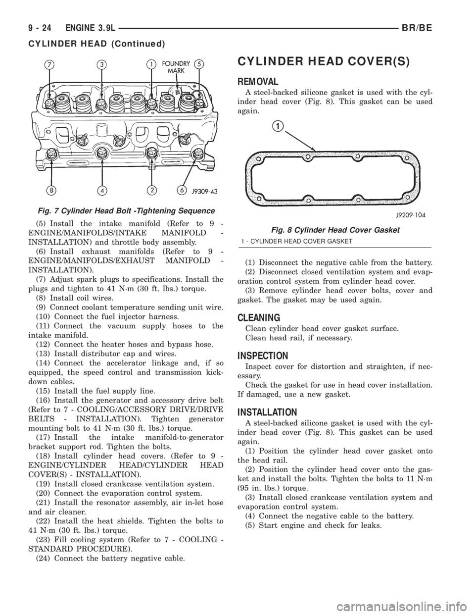
(3) Starting at top center, tighten all cylinder head
bolts, in sequence, to 68 N´m (50 ft. lbs.) torque (Fig.
7). Repeat procedure, tighten all cylinder head bolts
to 143 N´m (105 ft. lbs.) torque. Repeat procedure to
confirm that all bolts are at 143 N´m (105 ft. lbs.)
torque.
CAUTION: When tightening the rocker arm bolts, be
sure the piston in that cylinder is NOT at TDC. Con-
tact between the valves and piston could occur.
(4) Install push rods and rocker arm assemblies in
their original positions. Tighten the bolts to 28 N´m
(21 ft. lbs.) torque.
BR/BEENGINE 3.9L 9 - 23
CYLINDER HEAD (Continued)
Page 1171 of 2889
(5) Install the intake manifold (Refer to 9 -
ENGINE/MANIFOLDS/INTAKE MANIFOLD -
INSTALLATION) and throttle body assembly.
(6) Install exhaust manifolds (Refer to 9 -
ENGINE/MANIFOLDS/EXHAUST MANIFOLD -
INSTALLATION).
(7) Adjust spark plugs to specifications. Install the
plugs and tighten to 41 N´m (30 ft. lbs.) torque.
(8) Install coil wires.
(9) Connect coolant temperature sending unit wire.
(10) Connect the fuel injector harness.
(11) Connect the vacuum supply hoses to the
intake manifold.
(12) Connect the heater hoses and bypass hose.
(13) Install distributor cap and wires.
(14) Connect the accelerator linkage and, if so
equipped, the speed control and transmission kick-
down cables.
(15) Install the fuel supply line.
(16) Install the generator and accessory drive belt
(Refer to 7 - COOLING/ACCESSORY DRIVE/DRIVE
BELTS - INSTALLATION). Tighten generator
mounting bolt to 41 N´m (30 ft. lbs.) torque.
(17) Install the intake manifold-to-generator
bracket support rod. Tighten the bolts.
(18) Install cylinder head covers. (Refer to 9 -
ENGINE/CYLINDER HEAD/CYLINDER HEAD
COVER(S) - INSTALLATION).
(19) Install closed crankcase ventilation system.
(20) Connect the evaporation control system.
(21) Install the resonator assembly, air in-let hose
and air cleaner.
(22) Install the heat shields. Tighten the bolts to
41 N´m (30 ft. lbs.) torque.
(23) Fill cooling system (Refer to 7 - COOLING -
STANDARD PROCEDURE).
(24) Connect the battery negative cable.
CYLINDER HEAD COVER(S)
REMOVAL
A steel-backed silicone gasket is used with the cyl-
inder head cover (Fig. 8). This gasket can be used
again.
(1) Disconnect the negative cable from the battery.
(2) Disconnect closed ventilation system and evap-
oration control system from cylinder head cover.
(3) Remove cylinder head cover bolts, cover and
gasket. The gasket may be used again.
CLEANING
Clean cylinder head cover gasket surface.
Clean head rail, if necessary.
INSPECTION
Inspect cover for distortion and straighten, if nec-
essary.
Check the gasket for use in head cover installation.
If damaged, use a new gasket.
INSTALLATION
A steel-backed silicone gasket is used with the cyl-
inder head cover (Fig. 8). This gasket can be used
again.
(1) Position the cylinder head cover gasket onto
the head rail.
(2) Position the cylinder head cover onto the gas-
ket and install the bolts. Tighten the bolts to 11 N´m
(95 in. lbs.) torque.
(3) Install closed crankcase ventilation system and
evaporation control system.
(4) Connect the negative cable to the battery.
(5) Start engine and check for leaks.
Fig. 7 Cylinder Head Bolt -Tightening Sequence
Fig. 8 Cylinder Head Cover Gasket
1 - CYLINDER HEAD COVER GASKET
9 - 24 ENGINE 3.9LBR/BE
CYLINDER HEAD (Continued)
Page 1200 of 2889
DIAGNOSIS AND TESTINGÐINTAKE
MANIFOLD LEAKAGE
An intake manifold air leak is characterized by
lower than normal manifold vacuum. Also, one or
more cylinders may not be functioning.
WARNING: USE EXTREME CAUTION WHEN THE
ENGINE IS OPERATING. DO NOT STAND IN A
DIRECT LINE WITH THE FAN. DO NOT PUT YOUR
HANDS NEAR THE PULLEYS, BELTS, OR THE FAN.
DO NOT WEAR LOOSE CLOTHING.
(1) Start the engine.
(2) Spray a small stream of water at the suspected
leak area.
(3) If a change in RPMs, the area of the suspected
leak has been found.
(4) Repair as required.
REMOVAL
(1) Disconnect the negative cable from the battery.
(2) Drain the cooling system (Refer to 7 - COOL-
ING - STANDARD PROCEDURE).
(3) Remove the A/C compressor (Refer to 24 -
HEATING & AIR CONDITIONING/PLUMBING/A/C
COMPRESSOR - REMOVAL).
(4) Remove the generator (Refer to 8 - ELECTRI-
CAL/CHARGING/GENERATOR - REMOVAL).
(5) Remove the accessory drive bracket.
(6) Remove the air cleaner.
(7) Perform the Fuel System Pressure release pro-
cedure (Refer to 14 - FUEL SYSTEM/FUEL DELIV-
ERY - STANDARD PROCEDURE). Disconnect the
fuel lines (Refer to 14 - FUEL SYSTEM/FUEL
DELIVERY/QUICK CONNECT FITTING - STAN-
DARD PROCEDURE).
(8) Disconnect the accelerator linkage (Refer to 14
- FUEL SYSTEM/FUEL INJECTION/THROTTLE
CONTROL CABLE - REMOVAL) and if so equipped,
the speed control and transmission kickdown cables.
(9) Remove the return spring.
(10) Remove the distributor cap and wires.
(11) Disconnect the coil wires.
(12) Disconnect the heat indicator sending unit
wire.
(13) Disconnect the heater hoses and bypass hose.
(14) Remove the closed crankcase ventilation and
evaporation control systems.
(15) Remove intake manifold bolts.
(16) Lift the intake manifold and throttle body out
of the engine compartment as an assembly.
(17) Remove and discard the flange side gaskets
and the front and rear cross-over gaskets.(18) Remove the throttle body (Refer to 14 - FUEL
SYSTEM/FUEL INJECTION/THROTTLE BODY -
REMOVAL).
(19) If required, remove the plenum pan and gas-
ket. Discard gasket.
CLEANING
Clean manifold in solvent and blow dry with com-
pressed air.
Clean cylinder block front and rear gasket surfaces
using a suitable solvent.
The plenum pan rail must be clean and dry (free of
all foreign material).
INSPECTION
Inspect manifold for cracks.
Inspect mating surfaces of manifold for flatness
with a straightedge.
INSTALLATION
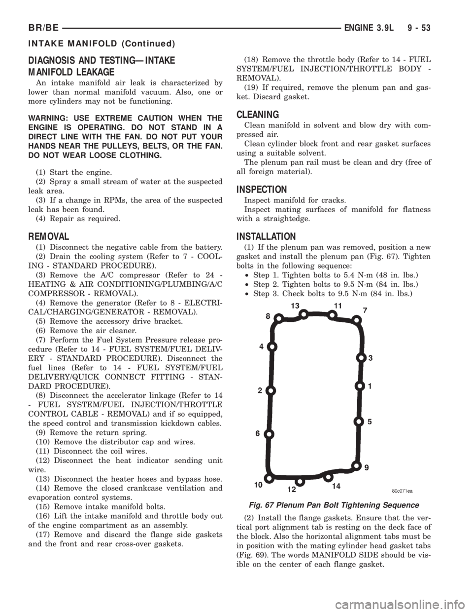
(1) If the plenum pan was removed, position a new
gasket and install the plenum pan (Fig. 67). Tighten
bolts in the following sequence:
²Step 1. Tighten bolts to 5.4 N´m (48 in. lbs.)
²Step 2. Tighten bolts to 9.5 N´m (84 in. lbs.)
²Step 3. Check bolts to 9.5 N´m (84 in. lbs.)
(2) Install the flange gaskets. Ensure that the ver-
tical port alignment tab is resting on the deck face of
the block. Also the horizontal alignment tabs must be
in position with the mating cylinder head gasket tabs
(Fig. 69). The words MANIFOLD SIDE should be vis-
ible on the center of each flange gasket.
Fig. 67 Plenum Pan Bolt Tightening Sequence
BR/BEENGINE 3.9L 9 - 53
INTAKE MANIFOLD (Continued)
Page 1201 of 2889
(3) Apply MopartGEN II Silicone Rubber Adhe-
sive Sealant, or equivalent, to the four corner joints.
An excessive amount of sealant is not required to
ensure a leak proof seal. However, an excessive
amount of sealant may reduce the effectiveness of
the flange gasket and crossÐover gaskets (Fig. 68).
The sealant should be approximately 5 mm (0.2 in)
in diameter.
(4) Install the front and rear cross-over gaskets.
(5) Using a new gasket, install the throttle body
onto the intake manifold (Refer to 14 - FUEL SYS-
TEM/FUEL INJECTION/THROTTLE BODY -
INSTALLATION).
(6) Carefully lower intake manifold into position
on the cylinder block and cylinder heads. After intake
manifold is in place, inspect to make sure seals are
in place.
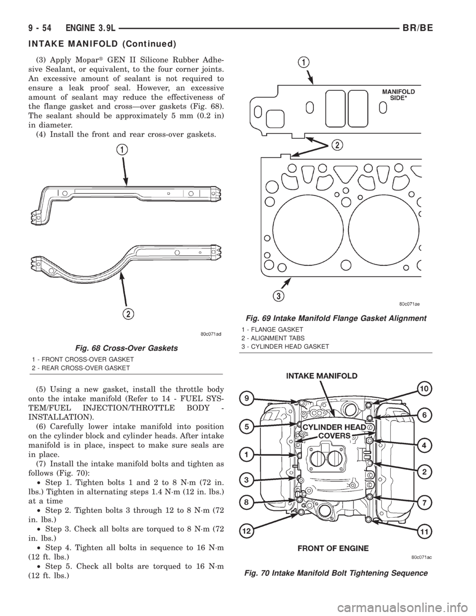
(7) Install the intake manifold bolts and tighten as
follows (Fig. 70):
²Step 1. Tighten bolts 1 and 2 to 8 N´m (72 in.
lbs.) Tighten in alternating steps 1.4 N´m (12 in. lbs.)
at a time
²Step 2. Tighten bolts 3 through 12 to 8 N´m (72
in. lbs.)
²Step 3. Check all bolts are torqued to 8 N´m (72
in. lbs.)
²Step 4. Tighten all bolts in sequence to 16 N´m
(12 ft. lbs.)
²Step 5. Check all bolts are torqued to 16 N´m
(12 ft. lbs.)
Fig. 68 Cross-Over Gaskets
1 - FRONT CROSS-OVER GASKET
2 - REAR CROSS-OVER GASKET
Fig. 69 Intake Manifold Flange Gasket Alignment
1 - FLANGE GASKET
2 - ALIGNMENT TABS
3 - CYLINDER HEAD GASKET
Fig. 70 Intake Manifold Bolt Tightening Sequence
9 - 54 ENGINE 3.9LBR/BE
INTAKE MANIFOLD (Continued)
Page 1227 of 2889
COOLING SYSTEM TESTER METHOD
WARNING: WITH COOLING SYSTEM TESTER IN
PLACE, PRESSURE WILL BUILD UP FAST. EXCES-
SIVE PRESSURE BUILT UP, BY CONTINUOUS
ENGINE OPERATION, MUST BE RELEASED TO A
SAFE PRESSURE POINT. NEVER PERMIT PRES-
SURE TO EXCEED 138 kPa (20 psi).
Install Cooling System Tester 7700 or equivalent to
pressure cap neck. Start the engine and observe the
tester's pressure gauge. If gauge pulsates with every
power stroke of a cylinder a combustion pressure
leak is evident.
CHEMICAL TEST METHOD
Combustion leaks into the cooling system can also
be checked by using Bloc-Chek Kit C-3685-A or
equivalent. Perform test following the procedures
supplied with the tool kit.
REMOVAL
(1) Disconnect the battery negative cable.
(2) Drain cooling system (Refer to 7 - COOLING -
STANDARD PROCEDURE).
(3) Remove the air cleaner resonator and duct
work.
(4) Remove the intake manifold-to-generator
bracket support rod. Remove the generator.
(5) Remove closed crankcase ventilation system.
(6) Disconnect the evaporation control system.
(7) Perform the Fuel System Pressure Release pro-
cedure (Refer to 14 - FUEL SYSTEM/FUEL DELIV-
ERY - STANDARD PROCEDURE). Disconnect the
fuel supply line (Refer to 14 - FUEL SYSTEM/FUEL
DELIVERY/QUICK CONNECT FITTING - STAN-
DARD PROCEDURE).
(8) Disconnect accelerator linkage and if so
equipped, the speed control and transmission kick-
down cables.
(9) Remove distributor cap and wires.
(10) Disconnect the coil wires.
(11) Disconnect heat indicator sending unit wire.
(12) Disconnect heater hoses and bypass hose.
(13) Remove cylinder head covers and gaskets
(Refer to 9 - ENGINE/CYLINDER HEAD/CYLIN-
DER HEAD COVER(S) - REMOVAL).
(14) Remove intake manifold (Refer to 9 -
ENGINE/MANIFOLDS/INTAKE MANIFOLD -
REMOVAL) and throttle body as an assembly. Dis-
card the flange side gaskets and the front and rear
cross-over gaskets.
(15) Remove exhaust manifolds (Refer to 9 -
ENGINE/MANIFOLDS/EXHAUST MANIFOLD -
REMOVAL).
(16) Remove rocker arm assemblies and push rods.
Identify to ensure installation in original locations.(17) Remove the head bolts from each cylinder
head and remove cylinder heads. Discard the cylin-
der head gasket.
(18) Remove spark plugs.
CLEANING
Clean all surfaces of cylinder block and cylinder
heads.
Clean cylinder block front and rear gasket surfaces
using a suitable solvent.
INSPECTION
Inspect all surfaces with a straightedge if there is
any reason to suspect leakage. If out-of-flatness
exceeds 0.00075mm (0.0001in.) times the span length
in any direction, either replace head or lightly
machine the head surface.
FOR EXAMPLE:ÐA 305 mm (12 in.) span is
0.102 mm (0.004 in.) out-of-flat. The allowable out-of-
flat is 305 x 0.00075 (12 x 0.00075) equals 0.23 mm
(0.009 in.). This amount of out-of-flat is acceptable.
The cylinder head surface finish should be
1.78-3.00 microns (70-125 microinches).
Inspect push rods. Replace worn or bent rods.
INSTALLATION
(1) Clean all surfaces of cylinder block and cylin-
der heads.
(2) Clean cylinder block front and rear gasket sur-
faces using a suitable solvent.
(3) Position new cylinder head gaskets onto the
cylinder block.
(4) Position cylinder heads onto head gaskets and
cylinder block.
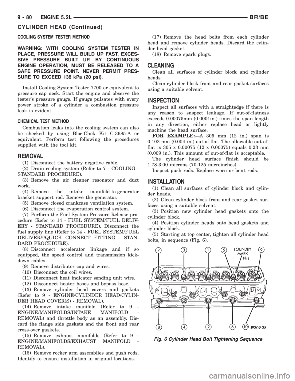
(5) Starting at top center, tighten all cylinder head
bolts, in sequence (Fig. 6).
Fig. 6 Cylinder Head Bolt Tightening Sequence
9 - 80 ENGINE 5.2LBR/BE
CYLINDER HEAD (Continued)
Page 1258 of 2889
INSTALLATION
(1) If removed, position new plenum gasket and
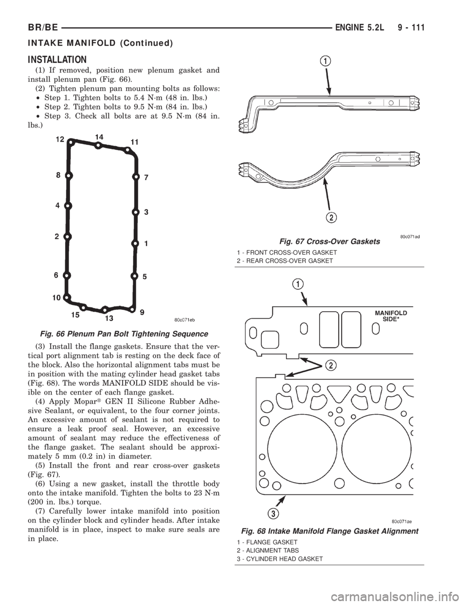
install plenum pan (Fig. 66).
(2) Tighten plenum pan mounting bolts as follows:
²Step 1. Tighten bolts to 5.4 N´m (48 in. lbs.)
²Step 2. Tighten bolts to 9.5 N´m (84 in. lbs.)
²Step 3. Check all bolts are at 9.5 N´m (84 in.
lbs.)
(3) Install the flange gaskets. Ensure that the ver-
tical port alignment tab is resting on the deck face of
the block. Also the horizontal alignment tabs must be
in position with the mating cylinder head gasket tabs
(Fig. 68). The words MANIFOLD SIDE should be vis-
ible on the center of each flange gasket.
(4) Apply MopartGEN II Silicone Rubber Adhe-
sive Sealant, or equivalent, to the four corner joints.
An excessive amount of sealant is not required to
ensure a leak proof seal. However, an excessive
amount of sealant may reduce the effectiveness of
the flange gasket. The sealant should be approxi-
mately 5 mm (0.2 in) in diameter.
(5) Install the front and rear cross-over gaskets
(Fig. 67).
(6) Using a new gasket, install the throttle body
onto the intake manifold. Tighten the bolts to 23 N´m
(200 in. lbs.) torque.
(7) Carefully lower intake manifold into position
on the cylinder block and cylinder heads. After intake
manifold is in place, inspect to make sure seals are
in place.
Fig. 66 Plenum Pan Bolt Tightening Sequence
Fig. 67 Cross-Over Gaskets
1 - FRONT CROSS-OVER GASKET
2 - REAR CROSS-OVER GASKET
Fig. 68 Intake Manifold Flange Gasket Alignment
1 - FLANGE GASKET
2 - ALIGNMENT TABS
3 - CYLINDER HEAD GASKET
BR/BEENGINE 5.2L 9 - 111
INTAKE MANIFOLD (Continued)
Page 1259 of 2889
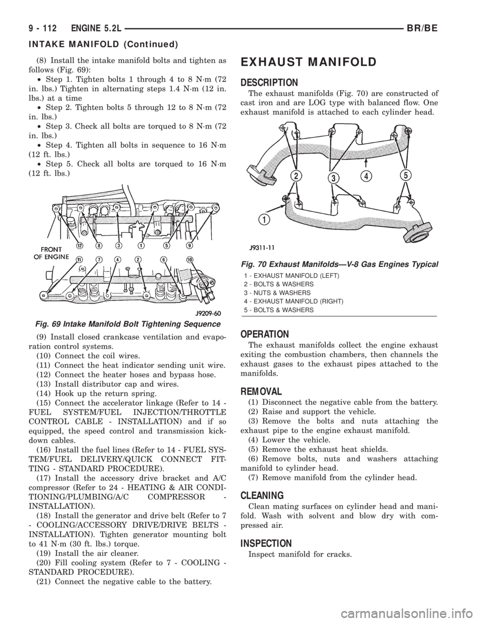
(8) Install the intake manifold bolts and tighten as
follows (Fig. 69):
²Step 1. Tighten bolts 1 through 4 to 8 N´m (72
in. lbs.) Tighten in alternating steps 1.4 N´m (12 in.
lbs.) at a time
²Step 2. Tighten bolts 5 through 12 to 8 N´m (72
in. lbs.)
²Step 3. Check all bolts are torqued to 8 N´m (72
in. lbs.)
²Step 4. Tighten all bolts in sequence to 16 N´m
(12 ft. lbs.)
²Step 5. Check all bolts are torqued to 16 N´m
(12 ft. lbs.)
(9) Install closed crankcase ventilation and evapo-
ration control systems.
(10) Connect the coil wires.
(11) Connect the heat indicator sending unit wire.
(12) Connect the heater hoses and bypass hose.
(13) Install distributor cap and wires.
(14) Hook up the return spring.
(15) Connect the accelerator linkage (Refer to 14 -
FUEL SYSTEM/FUEL INJECTION/THROTTLE
CONTROL CABLE - INSTALLATION) and if so
equipped, the speed control and transmission kick-
down cables.
(16) Install the fuel lines (Refer to 14 - FUEL SYS-
TEM/FUEL DELIVERY/QUICK CONNECT FIT-
TING - STANDARD PROCEDURE).
(17) Install the accessory drive bracket and A/C
compressor (Refer to 24 - HEATING & AIR CONDI-
TIONING/PLUMBING/A/C COMPRESSOR -
INSTALLATION).
(18) Install the generator and drive belt (Refer to 7
- COOLING/ACCESSORY DRIVE/DRIVE BELTS -
INSTALLATION). Tighten generator mounting bolt
to 41 N´m (30 ft. lbs.) torque.
(19) Install the air cleaner.
(20) Fill cooling system (Refer to 7 - COOLING -
STANDARD PROCEDURE).
(21) Connect the negative cable to the battery.EXHAUST MANIFOLD
DESCRIPTION
The exhaust manifolds (Fig. 70) are constructed of
cast iron and are LOG type with balanced flow. One
exhaust manifold is attached to each cylinder head.
OPERATION
The exhaust manifolds collect the engine exhaust
exiting the combustion chambers, then channels the
exhaust gases to the exhaust pipes attached to the
manifolds.
REMOVAL
(1) Disconnect the negative cable from the battery.
(2) Raise and support the vehicle.
(3) Remove the bolts and nuts attaching the
exhaust pipe to the engine exhaust manifold.
(4) Lower the vehicle.
(5) Remove the exhaust heat shields.
(6) Remove bolts, nuts and washers attaching
manifold to cylinder head.
(7) Remove manifold from the cylinder head.
CLEANING
Clean mating surfaces on cylinder head and mani-
fold. Wash with solvent and blow dry with com-
pressed air.
INSPECTION
Inspect manifold for cracks.
Fig. 69 Intake Manifold Bolt Tightening Sequence
Fig. 70 Exhaust ManifoldsÐV-8 Gas Engines Typical
1 - EXHAUST MANIFOLD (LEFT)
2 - BOLTS & WASHERS
3 - NUTS & WASHERS
4 - EXHAUST MANIFOLD (RIGHT)
5 - BOLTS & WASHERS
9 - 112 ENGINE 5.2LBR/BE
INTAKE MANIFOLD (Continued)
Page 1284 of 2889
Install Cooling System Tester 7700 or equivalent to
pressure cap neck. Start the engine and observe the
tester's pressure gauge. If gauge pulsates with every
power stroke of a cylinder a combustion pressure
leak is evident.
CHEMICAL TEST METHOD
Combustion leaks into the cooling system can also
be checked by using Bloc-Chek Kit C-3685-A or
equivalent. Perform test following the procedures
supplied with the tool kit.
REMOVAL
(1) Disconnect the battery negative cable.
(2) Drain cooling system (Refer to 7 - COOLING -
STANDARD PROCEDURE).
(3)
Remove the air cleaner resonator and duct work.
(4) Remove the intake manifold-to-generator
bracket support rod. Remove the generator.
(5) Remove closed crankcase ventilation system.
(6) Disconnect the evaporation control system.
(7) Perform the Fuel System Pressure Release pro-
cedure (Refer to 14 - FUEL SYSTEM/FUEL DELIV-
ERY - STANDARD PROCEDURE). Disconnect the
fuel supply line (Refer to 14 - FUEL SYSTEM/FUEL
DELIVERY/QUICK CONNECT FITTING - STAN-
DARD PROCEDURE).
(8) Disconnect accelerator linkage and if so
equipped, the speed control and transmission kick-
down cables.
(9) Remove distributor cap and wires.
(10) Disconnect the coil wires.
(11) Disconnect heat indicator sending unit wire.
(12) Disconnect heater hoses and bypass hose.
(13) Remove cylinder head covers and gaskets
(Refer to 9 - ENGINE/CYLINDER HEAD/CYLIN-
DER HEAD COVER(S) - REMOVAL).
(14)
Remove intake manifold (Refer to 9 - ENGINE/
MANIFOLDS/INTAKE MANIFOLD - REMOVAL) and
throttle body as an assembly. Discard the flange side
gaskets and the front and rear cross-over gaskets.
(15) Remove exhaust manifolds (Refer to 9 -
ENGINE/MANIFOLDS/EXHAUST MANIFOLD -
REMOVAL).
(16) Remove rocker arm assemblies and push rods.
Identify to ensure installation in original locations.
(17) Remove the head bolts from each cylinder
head and remove cylinder heads. Discard the cylin-
der head gasket.
(18) Remove spark plugs.
CLEANING
Clean all surfaces of cylinder block and cylinder
heads.
Clean cylinder block front and rear gasket surfaces
using a suitable solvent.
INSPECTION
Inspect all surfaces with a straightedge if there is
any reason to suspect leakage. If out-of-flatness
exceeds 0.00075mm/mm (0.0001in./in.) times the
span length in any direction, either replace head or
lightly machine the head surface.
FOR EXAMPLE:ÐA 305 mm (12 in.) span is
0.102 mm (0.004 in.) out-of-flat. The allowable out-of-
flat is 305 x 0.00075 (12 x 0.00075) equals 0.23 mm
(0.009 in.). This amount of out-of-flat is acceptable.
The cylinder head surface finish should be
1.78-3.00 microns (70-125 microinches).
Inspect push rods. Replace worn or bent rods.
INSTALLATION
(1) Clean all surfaces of cylinder block and cylin-
der heads.
(2) Clean cylinder block front and rear gasket sur-
faces using a suitable solvent.
(3) Position new cylinder head gaskets onto the
cylinder block.
(4) Position cylinder heads onto head gaskets and
cylinder block.
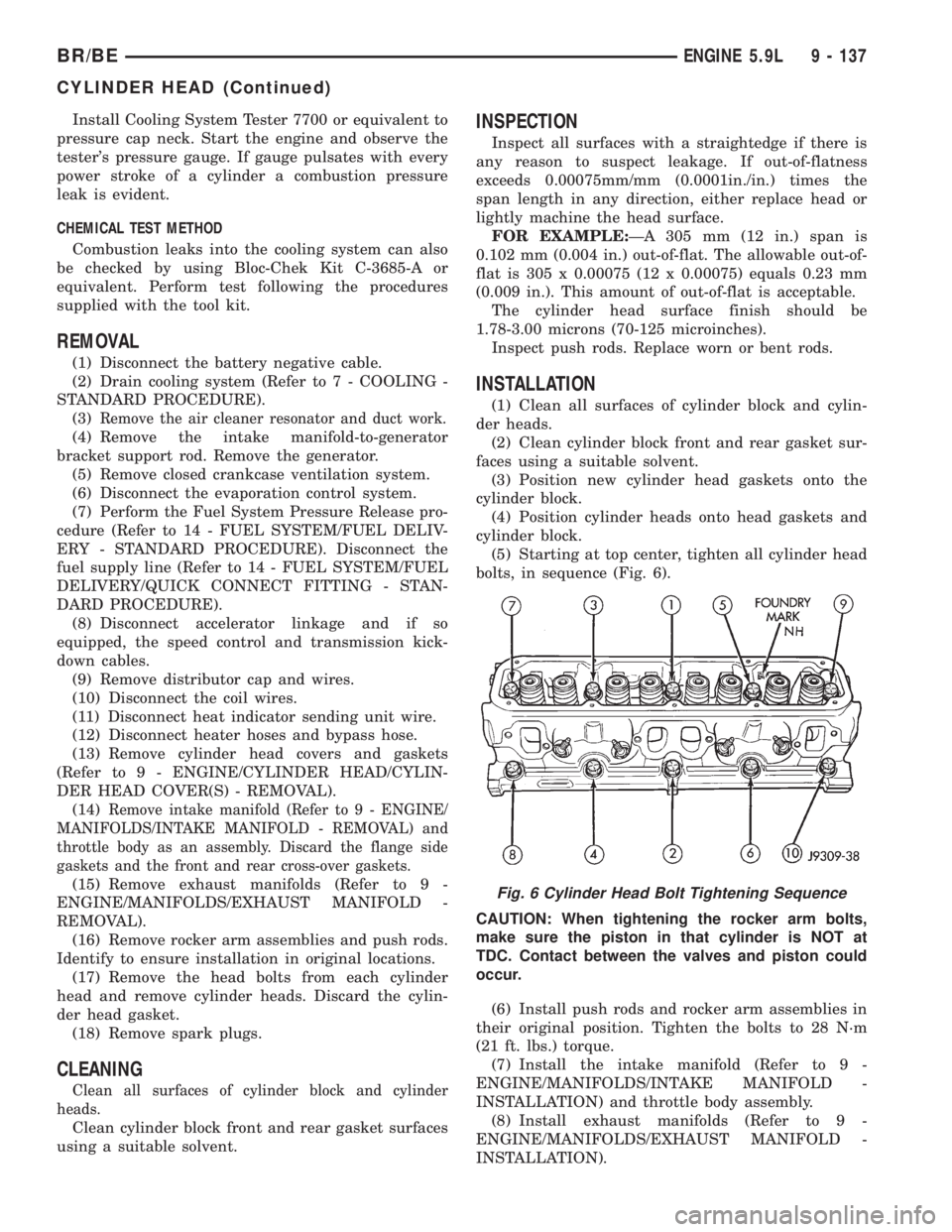
(5) Starting at top center, tighten all cylinder head
bolts, in sequence (Fig. 6).
CAUTION: When tightening the rocker arm bolts,
make sure the piston in that cylinder is NOT at
TDC. Contact between the valves and piston could
occur.
(6) Install push rods and rocker arm assemblies in
their original position. Tighten the bolts to 28 N´m
(21 ft. lbs.) torque.
(7) Install the intake manifold (Refer to 9 -
ENGINE/MANIFOLDS/INTAKE MANIFOLD -
INSTALLATION) and throttle body assembly.
(8) Install exhaust manifolds (Refer to 9 -
ENGINE/MANIFOLDS/EXHAUST MANIFOLD -
INSTALLATION).
Fig. 6 Cylinder Head Bolt Tightening Sequence
BR/BEENGINE 5.9L 9 - 137
CYLINDER HEAD (Continued)