2001 DODGE RAM vacuum hose
[x] Cancel search: vacuum hosePage 11 of 2889
VECI LABEL
DESCRIPTION
Vehicles equipped with 3.9L V-6 or 5.2L/5.9L V-8
LDC-gas powered engines have a VECI label.
The label combines both emission control informa-
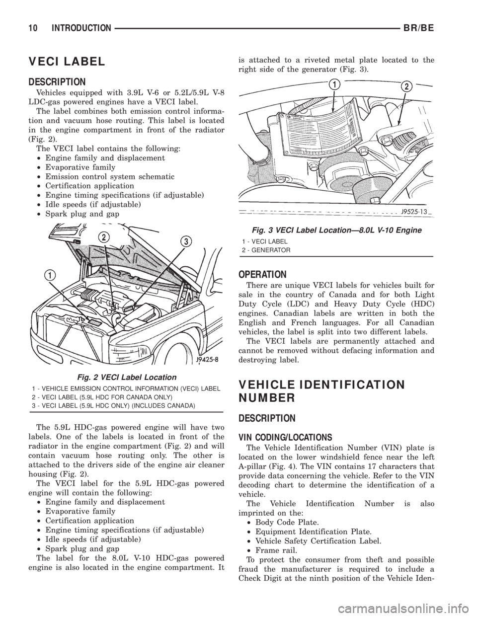
tion and vacuum hose routing. This label is located
in the engine compartment in front of the radiator
(Fig. 2).
The VECI label contains the following:
²Engine family and displacement
²Evaporative family
²Emission control system schematic
²Certification application
²Engine timing specifications (if adjustable)
²Idle speeds (if adjustable)
²Spark plug and gap
The 5.9L HDC-gas powered engine will have two
labels. One of the labels is located in front of the
radiator in the engine compartment (Fig. 2) and will
contain vacuum hose routing only. The other is
attached to the drivers side of the engine air cleaner
housing (Fig. 2).
The VECI label for the 5.9L HDC-gas powered
engine will contain the following:
²Engine family and displacement
²Evaporative family
²Certification application
²Engine timing specifications (if adjustable)
²Idle speeds (if adjustable)
²Spark plug and gap
The label for the 8.0L V-10 HDC-gas powered
engine is also located in the engine compartment. Itis attached to a riveted metal plate located to the
right side of the generator (Fig. 3).
OPERATION
There are unique VECI labels for vehicles built for
sale in the country of Canada and for both Light
Duty Cycle (LDC) and Heavy Duty Cycle (HDC)
engines. Canadian labels are written in both the
English and French languages. For all Canadian
vehicles, the label is split into two different labels.
The VECI labels are permanently attached and
cannot be removed without defacing information and
destroying label.
VEHICLE IDENTIFICATION
NUMBER
DESCRIPTION
VIN CODING/LOCATIONS
The Vehicle Identification Number (VIN) plate is
located on the lower windshield fence near the left
A-pillar (Fig. 4). The VIN contains 17 characters that
provide data concerning the vehicle. Refer to the VIN
decoding chart to determine the identification of a
vehicle.
The Vehicle Identification Number is also
imprinted on the:
²Body Code Plate.
²Equipment Identification Plate.
²Vehicle Safety Certification Label.
²Frame rail.
To protect the consumer from theft and possible
fraud the manufacturer is required to include a
Check Digit at the ninth position of the Vehicle Iden-
Fig. 2 VECI Label Location
1 - VEHICLE EMISSION CONTROL INFORMATION (VECI) LABEL
2 - VECI LABEL (5.9L HDC FOR CANADA ONLY)
3 - VECI LABEL (5.9L HDC ONLY) (INCLUDES CANADA)
Fig. 3 VECI Label LocationÐ8.0L V-10 Engine
1 - VECI LABEL
2 - GENERATOR
10 INTRODUCTIONBR/BE
Page 89 of 2889
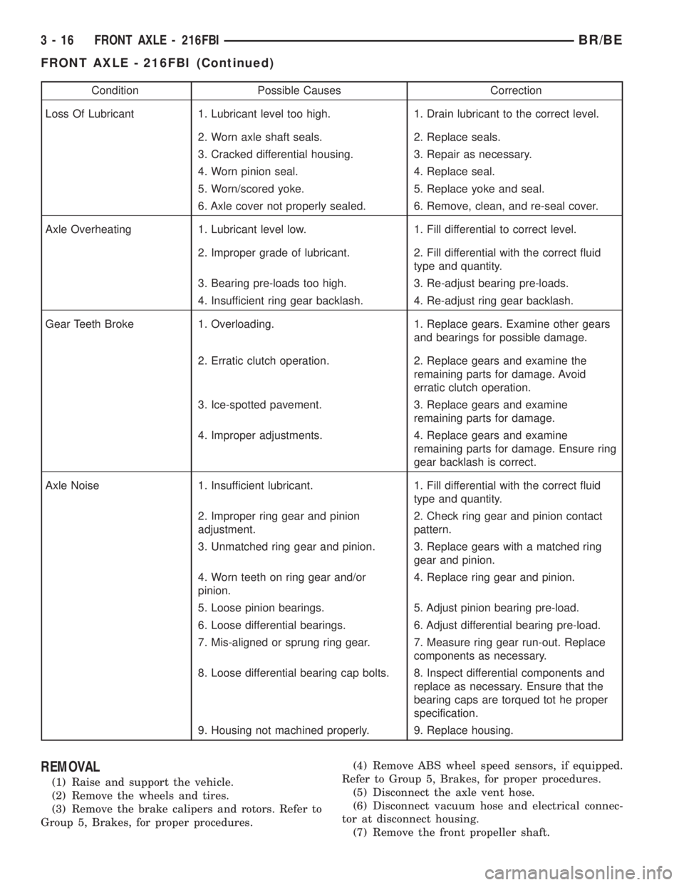
Condition Possible Causes Correction
Loss Of Lubricant 1. Lubricant level too high. 1. Drain lubricant to the correct level.
2. Worn axle shaft seals. 2. Replace seals.
3. Cracked differential housing. 3. Repair as necessary.
4. Worn pinion seal. 4. Replace seal.
5. Worn/scored yoke. 5. Replace yoke and seal.
6. Axle cover not properly sealed. 6. Remove, clean, and re-seal cover.
Axle Overheating 1. Lubricant level low. 1. Fill differential to correct level.
2. Improper grade of lubricant. 2. Fill differential with the correct fluid
type and quantity.
3. Bearing pre-loads too high. 3. Re-adjust bearing pre-loads.
4. Insufficient ring gear backlash. 4. Re-adjust ring gear backlash.
Gear Teeth Broke 1. Overloading. 1. Replace gears. Examine other gears
and bearings for possible damage.
2. Erratic clutch operation. 2. Replace gears and examine the
remaining parts for damage. Avoid
erratic clutch operation.
3. Ice-spotted pavement. 3. Replace gears and examine
remaining parts for damage.
4. Improper adjustments. 4. Replace gears and examine
remaining parts for damage. Ensure ring
gear backlash is correct.
Axle Noise 1. Insufficient lubricant. 1. Fill differential with the correct fluid
type and quantity.
2. Improper ring gear and pinion
adjustment.2. Check ring gear and pinion contact
pattern.
3. Unmatched ring gear and pinion. 3. Replace gears with a matched ring
gear and pinion.
4. Worn teeth on ring gear and/or
pinion.4. Replace ring gear and pinion.
5. Loose pinion bearings. 5. Adjust pinion bearing pre-load.
6. Loose differential bearings. 6. Adjust differential bearing pre-load.
7. Mis-aligned or sprung ring gear. 7. Measure ring gear run-out. Replace
components as necessary.
8. Loose differential bearing cap bolts. 8. Inspect differential components and
replace as necessary. Ensure that the
bearing caps are torqued tot he proper
specification.
9. Housing not machined properly. 9. Replace housing.
REMOVAL
(1) Raise and support the vehicle.
(2) Remove the wheels and tires.
(3) Remove the brake calipers and rotors. Refer to
Group 5, Brakes, for proper procedures.(4) Remove ABS wheel speed sensors, if equipped.
Refer to Group 5, Brakes, for proper procedures.
(5) Disconnect the axle vent hose.
(6) Disconnect vacuum hose and electrical connec-
tor at disconnect housing.
(7) Remove the front propeller shaft.
3 - 16 FRONT AXLE - 216FBIBR/BE
FRONT AXLE - 216FBI (Continued)
Page 90 of 2889
(8) Disconnect the stabilizer bar links at the axle
brackets.
(9) Disconnect the shock absorbers from axle
brackets.
(10) Disconnect the track bar from the axle
bracket.
(11) Disconnect the tie rod and drag link from the
steering knuckles.
(12) Position the axle with a suitable lifting device
under the axle assembly.
(13) Secure axle to lifting device.
(14) Mark suspension alignment cams for installa-
tion reference.
(15) Disconnect the upper and lower suspension
arms from the axle bracket.
(16) Lower the axle. The coil springs will drop
with the axle.
(17) Remove the coil springs from the axle bracket.
INSTALLATION
CAUTION: Suspension components with rubber
bushings should be tightened with the weight of the
vehicle on the suspension, at normal height. If
springs are not at their normal ride position, vehicle
ride comfort could be affected and premature bush-
ing wear may occur. Rubber bushings must never
be lubricated.
(1) Support the axle on a suitable lifting device.
(2) Secure axle to lifting device.
(3) Position the axle under the vehicle.
(4) Install the springs, retainer clip and bolts.
(5) Raise the axle and align it with the spring
pads.
(6) Position the upper and lower suspension arms
in the axle brackets. Install bolts, nuts and align the
suspension alignment cams to the reference marks.
Do not tighten at this time.
(7) Connect the track bar to the axle bracket and
install the bolt. Do not tighten at this time.
(8) Install the shock absorber and tighten bolts to
121 N´m (89 ft. lbs.) torque.
(9) Install the stabilizer bar link to the axle
bracket. Tighten the nut to 37 N´m (27 ft. lbs.)
torque.
(10) Install the drag link and tie rod to the steer-
ing knuckles and tighten the nuts to 88 N´m (65 ft.
lbs.) torque.
(11) Install the ABS wheel speed sensors, if
equipped. Refer to group 5, Brakes, for proper proce-
dures.
(12) Install the brake calipers and rotors. Refer to
Group 5, Brakes, for proper procedures.
(13) Connect the vent hose to the tube fitting.
(14) Connect vacuum hose and electrical connector
to disconnect housing.(15) Install front propeller shaft.
(16) Check and add differential lubricant, if neces-
sary. Refer to Lubricant Specifications in this section
for lubricant requirements.
(17) Install the wheel and tire assemblies.
(18) Remove the supports and lower the vehicle.
(19) Tighten the upper suspension arm nuts at
axle to 121 N´m (89 ft. lbs.) torque. Tighten the
upper suspension arm nuts at frame to 84 N´m (62 ft.
lbs.) torque.
(20) Tighten the lower suspension arm nuts at
axle to 84 N´m (62 ft. lbs.) torque. Tighten the lower
suspension arm nuts at frame to 119 N´m (88 ft. lbs.)
torque.
(21) Tighten the track bar bolt at the axle bracket
to 176 N´m (130 ft. lbs.) torque.
(22) Check the front wheel alignment.
ADJUSTMENTS
Ring and pinion gears are supplied as matched
sets only. The identifying numbers for the ring and
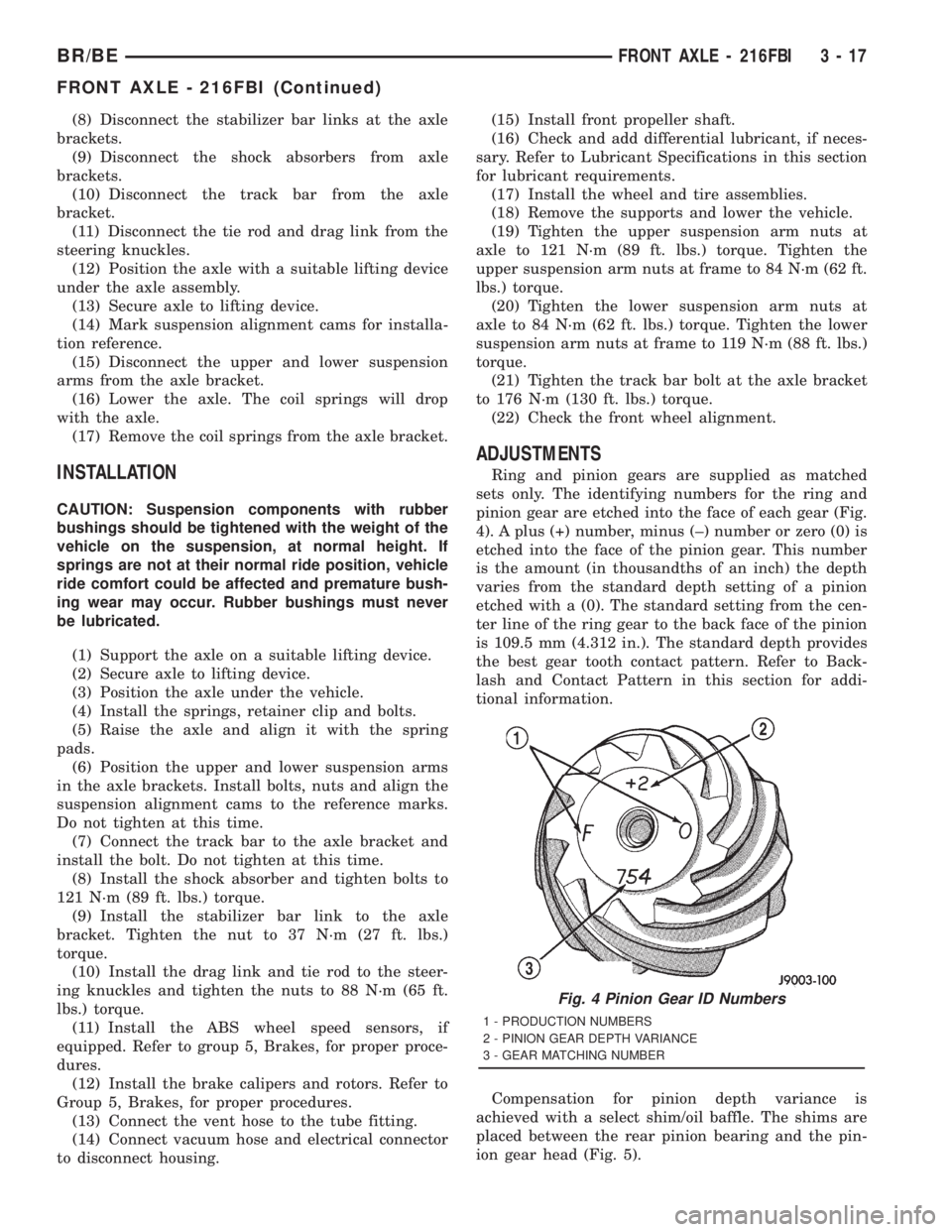
pinion gear are etched into the face of each gear (Fig.
4). A plus (+) number, minus (±) number or zero (0) is
etched into the face of the pinion gear. This number
is the amount (in thousandths of an inch) the depth
varies from the standard depth setting of a pinion
etched with a (0). The standard setting from the cen-
ter line of the ring gear to the back face of the pinion
is 109.5 mm (4.312 in.). The standard depth provides
the best gear tooth contact pattern. Refer to Back-
lash and Contact Pattern in this section for addi-
tional information.
Compensation for pinion depth variance is
achieved with a select shim/oil baffle. The shims are
placed between the rear pinion bearing and the pin-
ion gear head (Fig. 5).
Fig. 4 Pinion Gear ID Numbers
1 - PRODUCTION NUMBERS
2 - PINION GEAR DEPTH VARIANCE
3 - GEAR MATCHING NUMBER
BR/BEFRONT AXLE - 216FBI 3 - 17
FRONT AXLE - 216FBI (Continued)
Page 123 of 2889

REMOVAL
(1) Raise and support the vehicle.
(2) Remove the wheels and tires.
(3) Remove the brake calipers and rotors. Refer to
Group 5, Brakes, for proper procedures.
(4) Remove ABS wheel speed sensors, if equipped.
Refer to Group 5, Brakes, for proper procedures.
(5) Disconnect the axle vent hose.
(6) Disconnect vacuum hose and electrical connec-
tor at disconnect housing.
(7) Remove the front propeller shaft.
(8) Disconnect the stabilizer bar links at the axle
brackets.
(9) Disconnect the shock absorbers from axle
brackets.
(10) Disconnect the track bar from the axle
bracket.
(11) Disconnect the tie rod and drag link from the
steering knuckles.
(12) Position the axle with a suitable lifting device
under the axle assembly.
(13) Secure axle to lifting device.
(14) Mark suspension alignment cams for installa-
tion reference.
(15) Disconnect the upper and lower suspension
arms from the axle bracket.
(16) Lower the axle. The coil springs will drop
with the axle.
(17) Remove the coil springs from the axle bracket.
INSTALLATION
CAUTION: Suspension components with rubber
bushings should be tightened with the weight of the
vehicle on the suspension, at normal height. If
springs are not at their normal ride position, vehicle
ride comfort could be affected and premature bush-
ing wear may occur. Rubber bushings must never
be lubricated.
(1) Support the axle on a suitable lifting device.
(2) Secure axle to lifting device.
(3) Position the axle under the vehicle.
(4) Install the springs, retainer clip and bolts.
(5) Raise the axle and align it with the spring
pads.
(6) Position the upper and lower suspension arms
in the axle brackets. Install bolts, nuts and align the
suspension alignment cams to the reference marks.
Do not tighten at this time.
(7) Connect the track bar to the axle bracket and
install the bolt. Do not tighten at this time.
(8) Install the shock absorber and tighten bolts to
121 N´m (89 ft. lbs.) torque.(9) Install the stabilizer bar link to the axle
bracket. Tighten the nut to 37 N´m (27 ft. lbs.)
torque.
(10) Install the drag link and tie rod to the steer-
ing knuckles and tighten the nuts to 88 N´m (65 ft.
lbs.) torque.
(11) Install the ABS wheel speed sensors, if
equipped. Refer to group 5, Brakes, for proper proce-
dures.
(12) Install the brake calipers and rotors. Refer to
Group 5, Brakes, for proper procedures.
(13) Connect the vent hose to the tube fitting.
(14) Connect vacuum hose and electrical connector
to disconnect housing.
(15) Install front propeller shaft.
(16) Check and add differential lubricant, if neces-
sary. Refer to Lubricant Specifications in this section
for lubricant requirements.
(17) Install the wheel and tire assemblies.
(18) Remove the supports and lower the vehicle.
(19) Tighten the upper suspension arm nuts at
axle to 121 N´m (89 ft. lbs.) torque. Tighten the
upper suspension arm nuts at frame to 84 N´m (62 ft.
lbs.) torque.
(20) Tighten the lower suspension arm nuts at
axle to 84 N´m (62 ft. lbs.) torque. Tighten the lower
suspension arm nuts at frame to 119 N´m (88 ft. lbs.)
torque.
(21) Tighten the track bar bolt at the axle bracket
to 176 N´m (130 ft. lbs.) torque.
(22) Check the front wheel alignment.ADJUSTMENTS
Ring and pinion gears are supplied as matched
sets only. The identifying numbers for the ring and
pinion gear are etched into the face of each gear (Fig.
4). A plus (+) number, minus (±) number or zero (0) is
etched into the face of the pinion gear. This number
is the amount (in thousandths of an inch) the depth
varies from the standard depth setting of a pinion
etched with a (0). The standard setting from the cen-
ter line of the ring gear to the back face of the pinion
is 127 mm (5.00 in.). The standard depth provides
the best gear tooth contact pattern. Refer to Back-
lash and Contact Pattern in this section for addi-
tional information.
Compensation for pinion depth variance is
achieved with a select shim/oil baffle. The shims are
placed between the rear pinion bearing and the pin-
ion gear head (Fig. 5).
If a new gear set is being installed, note the depth
variance etched into both the original and replace-
ment pinion. Add or subtract this number from the
thickness of the original depth shim/oil slinger to
compensate for the difference in the depth variances.
Refer to the Depth Variance chart.
3 - 50 FRONT AXLE - 248FBIBR/BE
FRONT AXLE - 248FBI (Continued)
Page 276 of 2889
WARNING
WARNING: DUST AND DIRT ACCUMULATING ON
BRAKE PARTS DURING NORMAL USE MAY CON-
TAIN ASBESTOS FIBERS FROM PRODUCTION OR
AFTERMARKET LININGS. BREATHING EXCESSIVE
CONCENTRATIONS OF ASBESTOS FIBERS CAN
CAUSE SERIOUS BODILY HARM. EXERCISE CARE
WHEN SERVICING BRAKE PARTS. DO NOT CLEAN
BRAKE PARTS WITH COMPRESSED AIR OR BY
DRY BRUSHING. USE A VACUUM CLEANER SPE-
CIFICALLY DESIGNED FOR THE REMOVAL OF
ASBESTOS FIBERS FROM BRAKE COMPONENTS.
IF A SUITABLE VACUUM CLEANER IS NOT AVAIL-
ABLE, CLEANING SHOULD BE DONE WITH A
WATER DAMPENED CLOTH. DO NOT SAND, OR
GRIND BRAKE LINING UNLESS EQUIPMENT USED
IS DESIGNED TO CONTAIN THE DUST RESIDUE.
DISPOSE OF ALL RESIDUE CONTAINING ASBES-
TOS FIBERS IN SEALED BAGS OR CONTAINERS
TO MINIMIZE EXPOSURE TO YOURSELF AND OTH-
ERS. FOLLOW PRACTICES PRESCRIBED BY THE
OCCUPATIONAL SAFETY AND HEALTH ADMINIS-
TRATION AND THE ENVIRONMENTAL PROTECTION
AGENCY FOR THE HANDLING, PROCESSING, AND
DISPOSITION OF DUST OR DEBRIS THAT MAY
CONTAIN ASBESTOS FIBERS.
CAUTION: Never use gasoline, kerosene, alcohol,
motor oil, transmission fluid, or any fluid containing
mineral oil to clean the system components. These
fluids damage rubber cups and seals. Use only
fresh brake fluid or Mopar brake cleaner to clean or
flush brake system components. These are the only
cleaning materials recommended. If system contam-
ination is suspected, check the fluid for dirt, discol-
oration, or separation into distinct layers. Also
check the reservoir cap seal for distortion. Drain
and flush the system with new brake fluid if con-
tamination is suspected.
CAUTION: Use Mopar brake fluid, or an equivalent
quality fluid meeting SAE/DOT standards J1703 and
DOT 3. Brake fluid must be clean and free of con-
taminants. Use fresh fluid from sealed containers
only to ensure proper antilock component opera-
tion.
CAUTION: Use Mopar multi-mileage or high temper-
ature grease to lubricate caliper slide surfaces,
drum brake pivot pins, and shoe contact points on
the backing plates. Use multi-mileage grease or GE
661 or Dow 111 silicone grease on caliper slide pins
to ensure proper operation.
DIAGNOSIS AND TESTING - BASE BRAKE
SYSTEM
Base brake components consist of the brake shoes,
calipers, wheel cylinders, brake drums, rotors, brake
lines, master cylinder, booster, and parking brake
components.
Brake diagnosis involves determining if the prob-
lem is related to a mechanical, hydraulic, or vacuum
operated component.
The first diagnosis step is the preliminary check.
PRELIMINARY BRAKE CHECK
(1) Check condition of tires and wheels. Damaged
wheels and worn, damaged, or underinflated tires
can cause pull, shudder, vibration, and a condition
similar to grab.
(2) If complaint was based on noise when braking,
check suspension components. Jounce front and rear
of vehicle and listen for noise that might be caused
by loose, worn or damaged suspension or steering
components.
(3) Inspect brake fluid level and condition. Note
that the brake reservoir fluid level will decrease in
proportion to normal lining wear.Also note that
brake fluid tends to darken over time. This is
normal and should not be mistaken for contam-
ination.
(a) If fluid level is abnormally low, look for evi-
dence of leaks at calipers, wheel cylinders, brake
lines, and master cylinder.
(b) If fluid appears contaminated, drain out a
sample to examine. System will have to be flushed
if fluid is separated into layers, or contains a sub-
stance other than brake fluid. The system seals
and cups will also have to be replaced after flush-
ing. Use clean brake fluid to flush the system.
(4) Check parking brake operation. Verify free
movement and full release of cables and pedal. Also
note if vehicle was being operated with parking
brake partially applied.
(5) Check brake pedal operation. Verify that pedal
does not bind and has adequate free play. If pedal
lacks free play, check pedal and power booster for
being loose or for bind condition. Do not road test
until condition is corrected.
(6) Check booster vacuum check valve and hose.
(7) If components checked appear OK, road test
the vehicle.
ROAD TESTING
(1) If complaint involved low brake pedal, pump
pedal and note if it comes back up to normal height.
(2) Check brake pedal response with transmission
in Neutral and engine running. Pedal should remain
firm under constant foot pressure.
BR/BEBRAKES 5 - 5
HYDRAULIC/MECHANICAL (Continued)
Page 300 of 2889
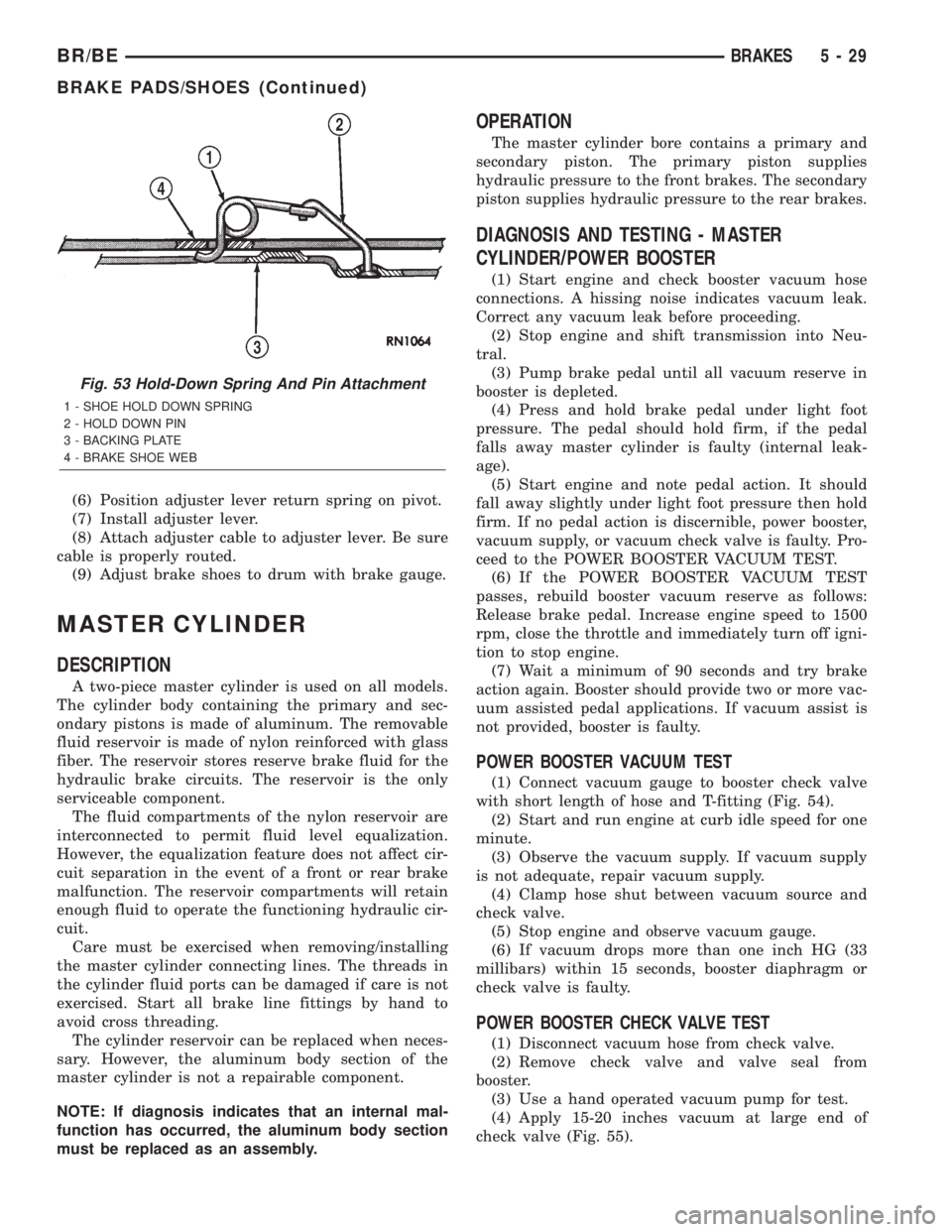
(6) Position adjuster lever return spring on pivot.
(7) Install adjuster lever.
(8) Attach adjuster cable to adjuster lever. Be sure
cable is properly routed.
(9) Adjust brake shoes to drum with brake gauge.
MASTER CYLINDER
DESCRIPTION
A two-piece master cylinder is used on all models.
The cylinder body containing the primary and sec-
ondary pistons is made of aluminum. The removable
fluid reservoir is made of nylon reinforced with glass
fiber. The reservoir stores reserve brake fluid for the
hydraulic brake circuits. The reservoir is the only
serviceable component.
The fluid compartments of the nylon reservoir are
interconnected to permit fluid level equalization.
However, the equalization feature does not affect cir-
cuit separation in the event of a front or rear brake
malfunction. The reservoir compartments will retain
enough fluid to operate the functioning hydraulic cir-
cuit.
Care must be exercised when removing/installing
the master cylinder connecting lines. The threads in
the cylinder fluid ports can be damaged if care is not
exercised. Start all brake line fittings by hand to
avoid cross threading.
The cylinder reservoir can be replaced when neces-
sary. However, the aluminum body section of the
master cylinder is not a repairable component.
NOTE: If diagnosis indicates that an internal mal-
function has occurred, the aluminum body section
must be replaced as an assembly.
OPERATION
The master cylinder bore contains a primary and
secondary piston. The primary piston supplies
hydraulic pressure to the front brakes. The secondary
piston supplies hydraulic pressure to the rear brakes.
DIAGNOSIS AND TESTING - MASTER
CYLINDER/POWER BOOSTER
(1) Start engine and check booster vacuum hose
connections. A hissing noise indicates vacuum leak.
Correct any vacuum leak before proceeding.
(2) Stop engine and shift transmission into Neu-
tral.
(3) Pump brake pedal until all vacuum reserve in
booster is depleted.
(4) Press and hold brake pedal under light foot
pressure. The pedal should hold firm, if the pedal
falls away master cylinder is faulty (internal leak-
age).
(5) Start engine and note pedal action. It should
fall away slightly under light foot pressure then hold
firm. If no pedal action is discernible, power booster,
vacuum supply, or vacuum check valve is faulty. Pro-
ceed to the POWER BOOSTER VACUUM TEST.
(6) If the POWER BOOSTER VACUUM TEST
passes, rebuild booster vacuum reserve as follows:
Release brake pedal. Increase engine speed to 1500
rpm, close the throttle and immediately turn off igni-
tion to stop engine.
(7) Wait a minimum of 90 seconds and try brake
action again. Booster should provide two or more vac-
uum assisted pedal applications. If vacuum assist is
not provided, booster is faulty.
POWER BOOSTER VACUUM TEST
(1) Connect vacuum gauge to booster check valve
with short length of hose and T-fitting (Fig. 54).
(2) Start and run engine at curb idle speed for one
minute.
(3) Observe the vacuum supply. If vacuum supply
is not adequate, repair vacuum supply.
(4) Clamp hose shut between vacuum source and
check valve.
(5) Stop engine and observe vacuum gauge.
(6) If vacuum drops more than one inch HG (33
millibars) within 15 seconds, booster diaphragm or
check valve is faulty.
POWER BOOSTER CHECK VALVE TEST
(1) Disconnect vacuum hose from check valve.
(2) Remove check valve and valve seal from
booster.
(3) Use a hand operated vacuum pump for test.
(4) Apply 15-20 inches vacuum at large end of
check valve (Fig. 55).
Fig. 53 Hold-Down Spring And Pin Attachment
1 - SHOE HOLD DOWN SPRING
2 - HOLD DOWN PIN
3 - BACKING PLATE
4 - BRAKE SHOE WEB
BR/BEBRAKES 5 - 29
BRAKE PADS/SHOES (Continued)
Page 301 of 2889
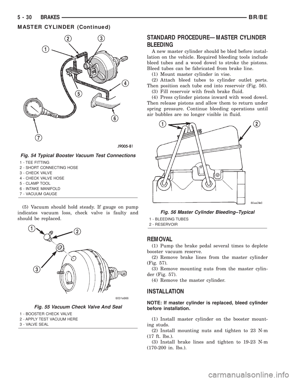
(5) Vacuum should hold steady. If gauge on pump
indicates vacuum loss, check valve is faulty and
should be replaced.
STANDARD PROCEDUREÐMASTER CYLINDER
BLEEDING
A new master cylinder should be bled before instal-
lation on the vehicle. Required bleeding tools include
bleed tubes and a wood dowel to stroke the pistons.
Bleed tubes can be fabricated from brake line.
(1) Mount master cylinder in vise.
(2) Attach bleed tubes to cylinder outlet ports.
Then position each tube end into reservoir (Fig. 56).
(3) Fill reservoir with fresh brake fluid.
(4) Press cylinder pistons inward with wood dowel.
Then release pistons and allow them to return under
spring pressure. Continue bleeding operations until
air bubbles are no longer visible in fluid.
REMOVAL
(1) Pump the brake pedal several times to deplete
booster vacuum reserve.
(2) Remove brake lines from the master cylinder
(Fig. 57).
(3) Remove mounting nuts from the master cylin-
der (Fig. 57).
(4) Remove the master cylinder.
INSTALLATION
NOTE: If master cylinder is replaced, bleed cylinder
before installation.
(1) Install master cylinder on the booster mount-
ing studs.
(2) Install mounting nuts and tighten to 23 N´m
(17 ft. lbs.).
(3) Install brake lines and tighten to 19-23 N´m
(170-200 in. lbs.).
Fig. 54 Typical Booster Vacuum Test Connections
1 - TEE FITTING
2 - SHORT CONNECTING HOSE
3 - CHECK VALVE
4 - CHECK VALVE HOSE
5 - CLAMP TOOL
6 - INTAKE MANIFOLD
7 - VACUUM GAUGE
Fig. 55 Vacuum Check Valve And Seal
1 - BOOSTER CHECK VALVE
2 - APPLY TEST VACUUM HERE
3 - VALVE SEAL
Fig. 56 Master Cylinder Bleeding±Typical
1 - BLEEDING TUBES
2 - RESERVOIR
5 - 30 BRAKESBR/BE
MASTER CYLINDER (Continued)
Page 345 of 2889
CONDITION POSSIBLE CAUSES CORRECTION
PRESSURE CAP IS
BLOWING OFF STEAM
AND/OR COOLANT TO
COOLANT TANK.
TEMPERATURE
GAUGE READING MAY
BE ABOVE NORMAL
BUT NOT HIGH.
COOLANT LEVEL MAY
BE HIGH IN COOLANT
RESERVE/OVERFLOW
TANK1. Pressure relief valve in radiator cap is
defective.1. Check condition of radiator cap and
cap seals. (Refer to 7 - COOLING/
ENGINE/RADIATOR PRESSURE CAP -
DIAGNOSIS AND TESTING). Replace
cap as necessary.
COOLANT LOSS TO
THE GROUND
WITHOUT PRESSURE
CAP BLOWOFF.
GAUGE READING
HIGH OR HOT1. Coolant leaks in radiator, cooling
system hoses, water pump or engine.1. Pressure test and repair as necessary.
(Refer to 7 - COOLING - DIAGNOSIS
AND TESTING).
DETONATION OR
PRE-IGNITION (NOT
CAUSED BY IGNITION
SYSTEM). GAUGE MAY
OR MAY NOT BE
READING HIGH1. Engine overheating. 1. Check reason for overheating and
repair as necessary.
2. Freeze point of coolant not correct.
Mixture is too rich or too lean.2. Check coolant concentration. (Refer to
LUBRICATION & MAINTENANCE/FLUID
TYPES - DESCRIPTION).
HOSE OR HOSES
COLLAPSE WHILE
ENGINE IS RUNNING1. Vacuum created in cooling system on
engine cool-down is not being relieved
through coolant reserve/overflow system.1. (a) Radiator cap relief valve stuck.
(Refer to 7 - COOLING/ENGINE/
RADIATOR PRESSURE CAP -
DIAGNOSIS AND TESTING). Replace if
necessary
(b) Hose between coolant reserve/
overflow tank and radiator is kinked.
Repair as necessary.
(c) Vent at coolant reserve/overflow tank
is plugged. Clean vent and repair as
necessary.
(d) Reserve/overflow tank is internally
blocked or plugged. Check for blockage
and repair as necessary.
7 - 10 COOLINGBR/BE
COOLING (Continued)