2001 DODGE RAM interior
[x] Cancel search: interiorPage 2 of 2889
INTRODUCTION
TABLE OF CONTENTS
page page
BODY CODE PLATE
DESCRIPTION............................1
FASTENER IDENTIFICATION
DESCRIPTION............................3
FASTENER USAGE
DESCRIPTION............................6
INTERNATIONAL VEHICLE CONTROL &
DISPLAY SYMBOLS
DESCRIPTION............................6
METRIC SYSTEM
DESCRIPTION............................6TORQUE REFERENCES
DESCRIPTION............................9
VECI LABEL
DESCRIPTION...........................10
OPERATION.............................10
VEHICLE IDENTIFICATION NUMBER
DESCRIPTION...........................10
VEHICLE SAFETY CERTIFICATION LABEL
DESCRIPTION...........................12
EQUIPMENT IDENTIFICATION PLATE
DESCRIPTION...........................12
BODY CODE PLATE
DESCRIPTION
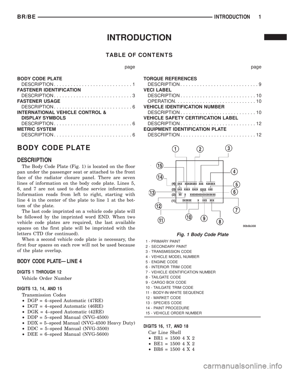
The Body Code Plate (Fig. 1) is located on the floor
pan under the passenger seat or attached to the front
face of the radiator closure panel. There are seven
lines of information on the body code plate. Lines 5,
6, and 7 are not used to define service information.
Information reads from left to right, starting with
line 4 in the center of the plate to line 1 at the bot-
tom of the plate.
The last code imprinted on a vehicle code plate will
be followed by the imprinted word END. When two
vehicle code plates are required, the last available
spaces on the first plate will be imprinted with the
letters CTD (for continued).
When a second vehicle code plate is necessary, the
first four spaces on each row will not be used because
of the plate overlap.
BODY CODE PLATEÐLINE 4
DIGITS 1 THROUGH 12
Vehicle Order Number
DIGITS 13, 14, AND 15
Transmission Codes
²DGP = 4±speed Automatic (47RE)
²DGT = 4±speed Automatic (46RE)
²DGK = 4±speed Automatic (42RE)
²DDP = 5±speed Manual (NVG-4500)
²DDX = 5±speed Manual (NVG-4500 Heavy Duty)
²DDC = 5±speed Manual (NVG-3500)
²DEE = 6±speed Manual (NVG-5600)DIGITS 16, 17, AND 18
Car Line Shell
²BR1=15004X2
²BE1=15004X2
²BR6=15004X4
Fig. 1 Body Code Plate
1 - PRIMARY PAINT
2 - SECONDARY PAINT
3 - TRANSMISSION CODE
4 - VEHICLE MODEL NUMBER
5 - ENGINE CODE
6 - INTERIOR TRIM CODE
7 - VEHICLE IDENTIFICATION NUMBER
8 - TAILGATE CODE
9 - CARGO BOX CODE
10 - TAILGATE TRIM CODE
11 - BODY-IN-WHITE SEQUENCE
12 - MARKET CODE
13 - SPECIES CODE
14 - PAINT PROCEDURE
15 - VEHICLE ORDER NUMBER
BR/BEINTRODUCTION 1
Page 3 of 2889
²BE6=15004X4
²BR2=25004X2
²BE2=25004X2
²BR7=25004X4
²BE7=25004X4
²BR3=35004X2
²BE3=35004X2
²BR8=35004X4
²BE8=35004X4
DIGIT 19
Price Class
²L = Ram Truck (All)
DIGITS 20 AND 21
Body Type
²
31 = Ram Truck Club Cab (138.7 in. Wheel Base)
²32 = Ram Truck Club Cab (154.7 in. Wheel Base)
²33 = Ram Truck Quad Cab (138.7 in. Wheel Base)
²34 = Ram Truck Quad Cab (154.7 in. Wheel Base)
²61 = Ram Truck (118.7 in. Wheel Base)
²62 = Ram Truck (134.7 in. Wheel Base)
²63 = Ram Truck Cab Chassis (138.7 in. Wheel
Base)
²
64 = Ram Truck Cab Chassis (162.7 in. Wheel
Base)
BODY CODE PLATEÐLINE 3
DIGITS 1,2, AND 3
Paint Procedure
²APA = Monotone
²AP9 = Special
²APB = Two-tone (Waterfall)
²APC = Two-tone (Centerband)
²APD = Two-tone (Lower break)
DIGIT 4
Open Space
DIGITS 5 THROUGH 8
Primary Paint
Refer to Group 23, Body for color codes.
DIGIT 9
Open Space
DIGITS 10 THROUGH 13
Secondary Paint
DIGIT 14
Open Space
DIGITS 15 THROUGH 18
Interior Trim CodeDIGIT 19
Open Space
DIGITS 20, 21, AND 22
Engine Code
²EHC = 3.9 L 6 cyl. MPI Gasoline
²ELF = 5.2 L 8 cyl. MPI Gasoline
²ELN = 5.2 L 8 cyl. (CNG)
²EML = 5.9 L 8 cyl. MPI Gasoline
²EMM = 5.9 L 8 cyl. MPI Gasoline (Heavy Duty)
²ETC = 5.9 L 6 cyl. Turbo Diesel
²EWA = 8.0 L 10 cyl. MPI Gasoline
BODY CODE PLATEÐLINE 2
DIGIT 1 Open Space
DIGITS 2 AND 3 Species Code. (Used for Manufacturing)
DIGIT 4
Open Space
DIGIT 5
Market Code
²B = International
²C = Canada
²M = Mexico
²U = United States
DIGIT 6
Open Space
DIGITS 7 THROUGH 23
Vehicle Identification Number (VIN)
Refer to Vehicle Identification Number (VIN) para-
graph for proper breakdown of VIN code.
BODY CODE PLATEÐLINE 1
DIGITS 1 THROUGH 6 Body-in-white assembly sequence.
DIGIT 7
Open Space
DIGIT 8 Tailgate trim code.
DIGIT 9
Open Space
DIGITS 10 THROUGH 12 Cargo box code
²XBS = Sweptline
DIGIT 13
Open Space
2 INTRODUCTIONBR/BE
BODY CODE PLATE (Continued)
Page 317 of 2889
Oil contamination indicates a leak at either the
rear main seal or transmission input shaft. Oil leak-
age produces a residue of oil on the housing interior
and on the clutch cover and flywheel. Heat buildup
caused by slippage between the cover, disc and fly-
wheel, can sometimes bake the oil residue onto the
components. The glaze-like residue ranges in color
from amber to black.
Road splash contamination means dirt/water is
entering the clutch housing due to loose bolts, hous-
ing cracks or through hydraulic line openings. Driv-
ing through deep water puddles can force water/road
splash into the housing through such openings.
Clutch fluid leaks are usually from damaged slave
cylinder push rod seals.
IMPROPER RELEASE OR CLUTCH ENGAGEMENT
Clutch release or engagement problems are caused
by wear or damage to one or more clutch compo-
nents. A visual inspection of the release components
will usually reveal the problem part.
Release problems can result in hard shifting and
noise. Items to look for are: leaks at the clutch cylin-
ders and interconnecting line; loose slave cylinder
bolts; worn/loose release fork and pivot stud; dam-
aged release bearing; and a worn clutch disc, or pres-
sure plate.
Normal condensation in vehicles that are stored or
out of service for long periods of time can generate
enough corrosion to make the disc stick to the fly-
wheel, or pressure plate. If this condition is experi-
enced, correction only requires that the disc be
loosened manually through the inspection plate open-
ing.
Engagement problems usually result in slip, chat-
ter/shudder, and noisy operation. The primary causes
are clutch disc contamination; clutch disc wear; mis-
alignment, or distortion; flywheel damage; or a com-
bination of the foregoing. A visual inspection is
required to determine the part actually causing the
problem.
CLUTCH MISALIGNMENT
Clutch components must be in proper alignment
with the crankshaft and transmission input shaft.
Misalignment caused by excessive runout or warpage
of any clutch component will cause grab, chatter and
improper clutch release.
CLUTCH COVER AND DISC RUNOUT
Check the clutch disc before installation. Axial
(face) runout of anewdisc should not exceed 0.50
mm (0.020 in.). Measure runout about 6 mm (1/4 in.)
from the outer edge of the disc facing. Obtain
another disc if runout is excessive.Check condition of the clutch before installation. A
warped cover or diaphragm spring will cause grab
and incomplete release or engagement. Be careful
when handling the cover and disc. Impact can distort
the cover, diaphragm spring, release fingers and the
hub of the clutch disc.
Use an alignment tool when positioning the disc on
the flywheel. The tool prevents accidental misalign-
ment which could result in cover distortion and disc
damage.
A frequent cause of clutch cover distortion (and con-
sequent misalignment) is improper bolt tightening.
CLUTCH FLYWHEEL RUNOUT
Check flywheel runout whenever misalignment is
suspected. Flywheel runout should not exceed 0.08
mm (0.003 in.). Measure runout at the outer edge of
the flywheel face with a dial indicator. Mount the
indicator on the rear face of the engine block.
Common causes of runout are:
²heat warpage
²improper machining
²incorrect bolt tightening
²improper seating on crankshaft flange shoulder
²foreign material on crankshaft flange
Flywheel machining is not recommended. The fly-
wheel clutch surface is machined to a unique contour
and machining will negate this feature. However,
minor flywheel scoring can be cleaned up by hand with
180 grit emery, or with surface grinding equipment.
Remove only enough material to reduce scoring
(approximately 0.001 - 0.003 in.). Heavy stock removal
isnot recommended.
Replace the flywheel if scoring
is severe and deeper than 0.076 mm (0.003 in.).
Excessive stock removal can result in flywheel crack-
ing or warpage after installation; it can also weaken
the flywheel and interfere with proper clutch release.
Clean the crankshaft flange before mounting the
flywheel. Dirt and grease on the flange surface may
cock the flywheel causing excessive runout. Use new
bolts when remounting a flywheel and secure the
bolts with MopartLock And Seal. Tighten flywheel
bolts to specified torque only. Overtightening can dis-
tort the flywheel hub causing runout.
DIAGNOSIS CHART
The clutch inspection chart (Fig. 3) outlines items to
be checked before and during clutch installation. Use
the chart as a check list to help avoid overlooking
potential problem sources during service operations.
The diagnosis charts describe common clutch prob-
lems, causes and correction. Fault conditions are listed
at the top of each chart. Conditions, causes and correc-
tive action are outlined in the indicated columns.
The charts are provided as a convenient reference
when diagnosing faulty clutch operation.
6 - 4 CLUTCHBR/BE
CLUTCH (Continued)
Page 340 of 2889
ACCESSING DIAGNOSTIC TROUBLE CODES
To read DTC's and to obtain cooling system data,
(Refer to 25 - EMISSIONS CONTROL - DESCRIP-
TION).
ERASING TROUBLE CODES
After the problem has been repaired, use the DRB
scan tool to erase a DTC. Refer to the appropriate
Powertrain Diagnostic Procedures service informa-
tion for operation of the DRB scan tool.
DIAGNOSIS AND TESTINGÐCOOLING SYSTEM
LEAKS
ULTRAVIOLET LIGHT METHOD
A leak detection additive is available through the
parts department that can be added to cooling sys-
tem. The additive is highly visible under ultraviolet
light (black light). Pour one ounce of additive into
cooling system. Place heater control unit in HEAT
position. Start and operate engine until radiator
upper hose is warm to touch. Aim the commercially
available black light tool at components to be
checked. If leaks are present, black light will cause
additive to glow a bright green color.
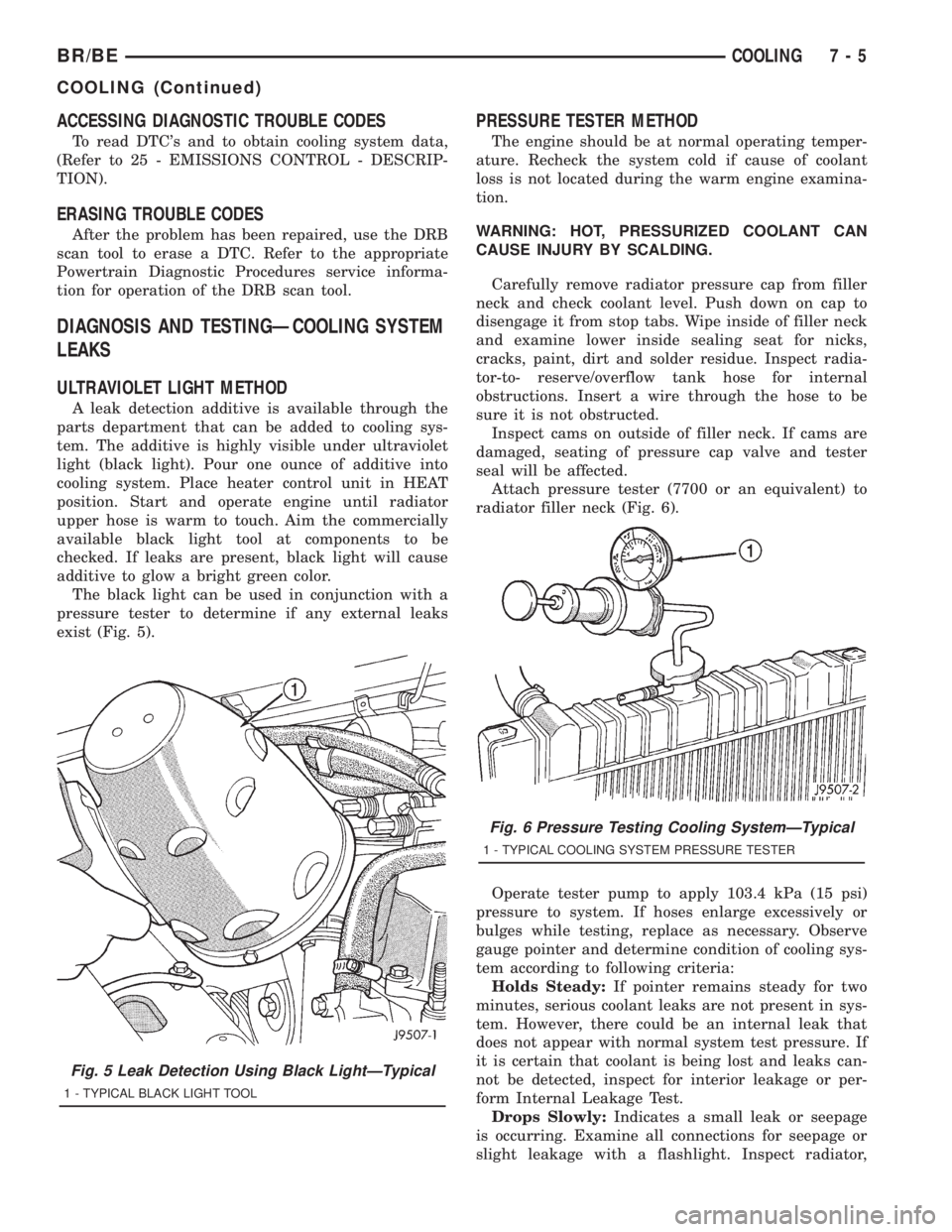
The black light can be used in conjunction with a
pressure tester to determine if any external leaks
exist (Fig. 5).
PRESSURE TESTER METHOD
The engine should be at normal operating temper-
ature. Recheck the system cold if cause of coolant
loss is not located during the warm engine examina-
tion.
WARNING: HOT, PRESSURIZED COOLANT CAN
CAUSE INJURY BY SCALDING.
Carefully remove radiator pressure cap from filler
neck and check coolant level. Push down on cap to
disengage it from stop tabs. Wipe inside of filler neck
and examine lower inside sealing seat for nicks,
cracks, paint, dirt and solder residue. Inspect radia-
tor-to- reserve/overflow tank hose for internal
obstructions. Insert a wire through the hose to be
sure it is not obstructed.
Inspect cams on outside of filler neck. If cams are
damaged, seating of pressure cap valve and tester
seal will be affected.
Attach pressure tester (7700 or an equivalent) to
radiator filler neck (Fig. 6).
Operate tester pump to apply 103.4 kPa (15 psi)
pressure to system. If hoses enlarge excessively or
bulges while testing, replace as necessary. Observe
gauge pointer and determine condition of cooling sys-
tem according to following criteria:
Holds Steady:If pointer remains steady for two
minutes, serious coolant leaks are not present in sys-
tem. However, there could be an internal leak that
does not appear with normal system test pressure. If
it is certain that coolant is being lost and leaks can-
not be detected, inspect for interior leakage or per-
form Internal Leakage Test.
Drops Slowly:Indicates a small leak or seepage
is occurring. Examine all connections for seepage or
slight leakage with a flashlight. Inspect radiator,
Fig. 5 Leak Detection Using Black LightÐTypical
1 - TYPICAL BLACK LIGHT TOOL
Fig. 6 Pressure Testing Cooling SystemÐTypical
1 - TYPICAL COOLING SYSTEM PRESSURE TESTER
BR/BECOOLING 7 - 5
COOLING (Continued)
Page 427 of 2889
Audio System Diagnosis
CONDITION POSSIBLE CAUSE CORRECTION
NO/POOR TAPE
OPERATION1. Faulty tape. 1. Insert known good tape and test operation.
2. Foreign objects behind
tape door.2. Remove foreign objects and test operation.
3. Dirty cassette tape
head.3. Clean head with Mopar Cassette Head Cleaner.
4. Faulty tape deck. 4. Exchange or replace radio, if required.
NO COMPACT DISC
OPERATION1. Faulty CD. 1. Insert known good CD and test operation.
2. Foreign material on
CD.2. Clean CD and test operation.
3. Condensation on CD
or optics.3. Allow temperature of vehicle interior to stabilize and test
operation.
4. Faulty CD player. 4. Exchange or replace radio, if required.
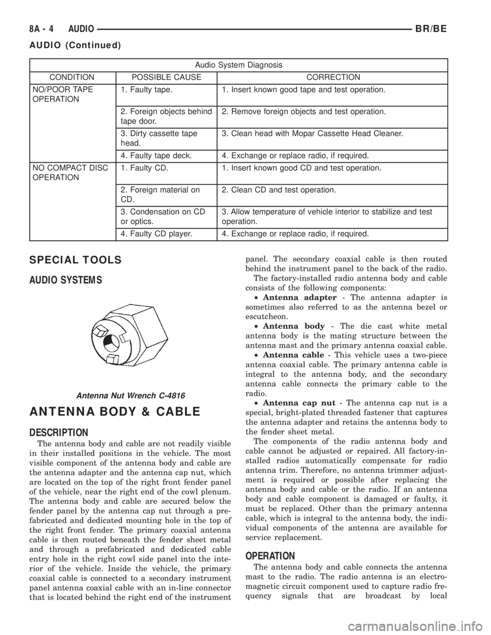
SPECIAL TOOLS
AUDIO SYSTEMS
ANTENNA BODY & CABLE
DESCRIPTION
The antenna body and cable are not readily visible
in their installed positions in the vehicle. The most
visible component of the antenna body and cable are
the antenna adapter and the antenna cap nut, which
are located on the top of the right front fender panel
of the vehicle, near the right end of the cowl plenum.
The antenna body and cable are secured below the
fender panel by the antenna cap nut through a pre-
fabricated and dedicated mounting hole in the top of
the right front fender. The primary coaxial antenna
cable is then routed beneath the fender sheet metal
and through a prefabricated and dedicated cable
entry hole in the right cowl side panel into the inte-
rior of the vehicle. Inside the vehicle, the primary
coaxial cable is connected to a secondary instrument
panel antenna coaxial cable with an in-line connector
that is located behind the right end of the instrumentpanel. The secondary coaxial cable is then routed
behind the instrument panel to the back of the radio.
The factory-installed radio antenna body and cable
consists of the following components:
²Antenna adapter- The antenna adapter is
sometimes also referred to as the antenna bezel or
escutcheon.
²Antenna body- The die cast white metal
antenna body is the mating structure between the
antenna mast and the primary antenna coaxial cable.
²Antenna cable- This vehicle uses a two-piece
antenna coaxial cable. The primary antenna cable is
integral to the antenna body, and the secondary
antenna cable connects the primary cable to the
radio.
²Antenna cap nut- The antenna cap nut is a
special, bright-plated threaded fastener that captures
the antenna adapter and retains the antenna body to
the fender sheet metal.
The components of the radio antenna body and
cable cannot be adjusted or repaired. All factory-in-
stalled radios automatically compensate for radio
antenna trim. Therefore, no antenna trimmer adjust-
ment is required or possible after replacing the
antenna body and cable or the radio. If an antenna
body and cable component is damaged or faulty, it
must be replaced. Other than the primary antenna
cable, which is integral to the antenna body, the indi-
vidual components of the antenna are available for
service replacement.
OPERATION
The antenna body and cable connects the antenna
mast to the radio. The radio antenna is an electro-
magnetic circuit component used to capture radio fre-
quency signals that are broadcast by local
Antenna Nut Wrench C-4816
8A - 4 AUDIOBR/BE
AUDIO (Continued)
Page 442 of 2889
(8) Turn the radio receiver off. Turn the ignition
switch to the Off position. Disconnect and isolate the
battery negative cable. Disconnect the wire harness
connector for the Infinity-amplified front door-
mounted speaker on the same side of the vehicle as
the inoperative speaker. Check both the amplified
feed (+) circuit and amplified return (±) circuit cavi-
ties for the inoperative speaker location in the body
half of the front door speaker wire harness connector
for continuity to ground. In each case, there should
be no continuity. If OK, go to Step 9. If not OK,
repair the shorted amplified feed (+) and/or amplified
return (±) circuit(s) as required.
(9) Disconnect the wire harness connector at the
inoperative speaker. Check for continuity between
the amplified feed (+) circuit cavities in the body half
of the wire harness connector for the Infinity-ampli-
fied front door-mounted speaker on the same side of
the vehicle as the inoperative speaker and the inop-
erative speaker wire harness connector. Repeat the
check between the amplified return (±) circuit cavi-
ties in the body half of the wire harness connector for
the Infinity-amplified front door-mounted speaker on
the same side of the vehicle as the inoperative
speaker and the inoperative speaker wire harness
connector. In each case, there should be continuity. If
OK, go to Step 10. If not OK, repair the open ampli-
fied feed (+) and/or amplified return (±) circuit(s) as
required.
(10) Check the resistance between the amplified
feed (+) circuit and amplified return (±) circuit cavi-
ties for the inoperative speaker in the body half of
the wire harness connector for the Infinity-amplified
front door-mounted speaker on the same side of the
vehicle as the inoperative speaker. The meter should
read between 2.5 and 4 ohms (speaker resistance). If
OK, replace the faulty front door-mounted Infinity
speaker and amplifier unit. If not OK, replace the
faulty A-pillar or rear-mounted Infinity speaker.
A-PILLAR TWEETER SPEAKER
REMOVAL
The A-pillar-mounted tweeters are used only with
the optional Infinity premium speaker package.
(1) Disconnect and isolate the battery negative
cable.
(2) If the vehicle is so equipped, remove the grab
handle from the A-pillar. Refer to Body, Interior for
the procedures.
(3) Disengage the trim from the A-pillar. Refer to
Body, Interior for the procedures.
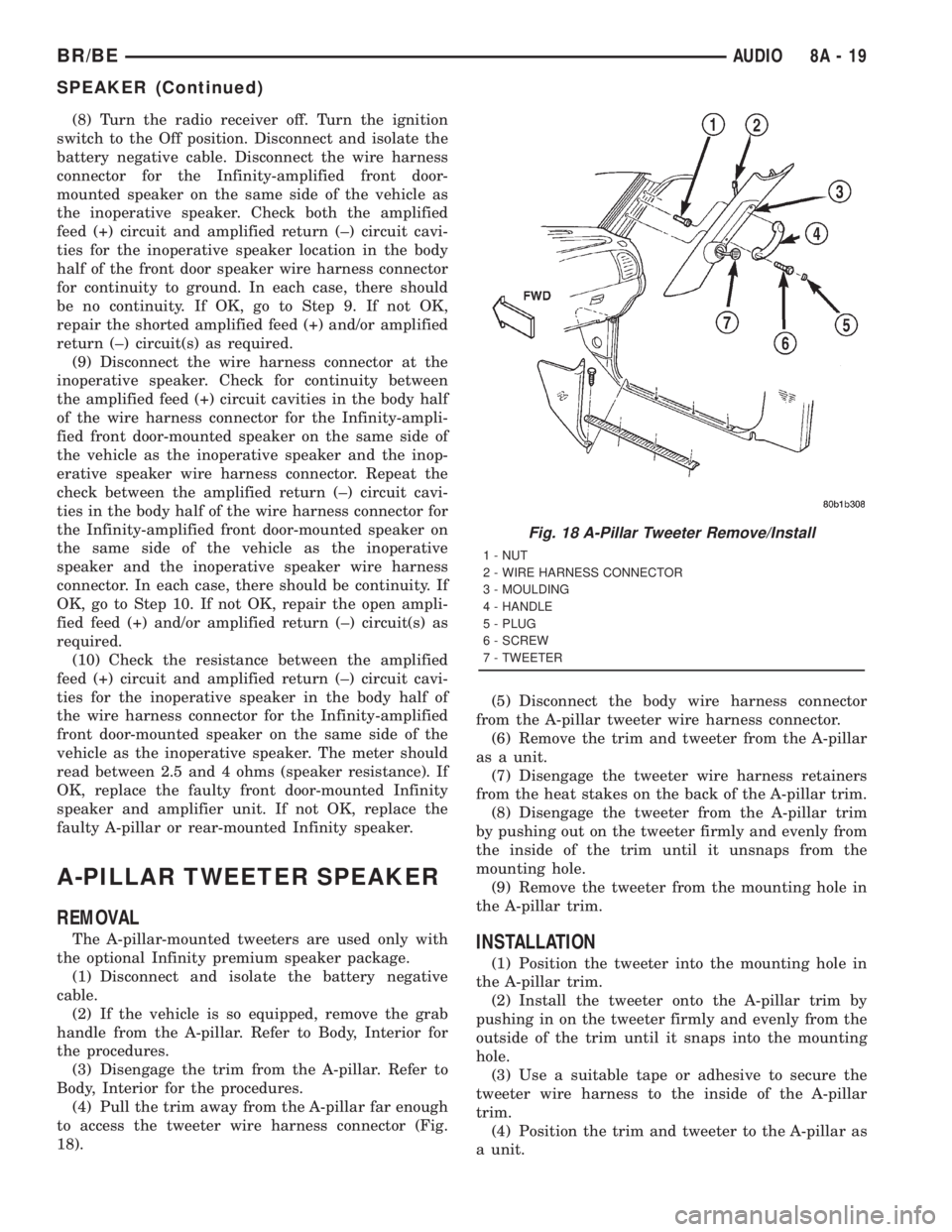
(4) Pull the trim away from the A-pillar far enough
to access the tweeter wire harness connector (Fig.
18).(5) Disconnect the body wire harness connector
from the A-pillar tweeter wire harness connector.
(6) Remove the trim and tweeter from the A-pillar
as a unit.
(7) Disengage the tweeter wire harness retainers
from the heat stakes on the back of the A-pillar trim.
(8) Disengage the tweeter from the A-pillar trim
by pushing out on the tweeter firmly and evenly from
the inside of the trim until it unsnaps from the
mounting hole.
(9) Remove the tweeter from the mounting hole in
the A-pillar trim.INSTALLATION
(1) Position the tweeter into the mounting hole in
the A-pillar trim.
(2) Install the tweeter onto the A-pillar trim by
pushing in on the tweeter firmly and evenly from the
outside of the trim until it snaps into the mounting
hole.
(3) Use a suitable tape or adhesive to secure the
tweeter wire harness to the inside of the A-pillar
trim.
(4) Position the trim and tweeter to the A-pillar as
a unit.
Fig. 18 A-Pillar Tweeter Remove/Install
1 - NUT
2 - WIRE HARNESS CONNECTOR
3 - MOULDING
4 - HANDLE
5 - PLUG
6 - SCREW
7 - TWEETER
BR/BEAUDIO 8A - 19
SPEAKER (Continued)
Page 443 of 2889
(5) Reconnect the body wire harness connector to
the A-pillar tweeter wire harness connector.
(6) Engage the trim onto the A-pillar. Refer to
Body, Interior for the procedures.
(7) If the vehicle is so equipped, install the grab
handle onto the A-pillar. Refer to Body, Interior for
the procedures.
(8) Reconnect the battery negative cable.
FRONT DOOR SPEAKER
REMOVAL
(1) Disconnect and isolate the battery negative
cable.
(2) Remove the trim panel from the front door.
Refer to Body, Door Front for the procedures.
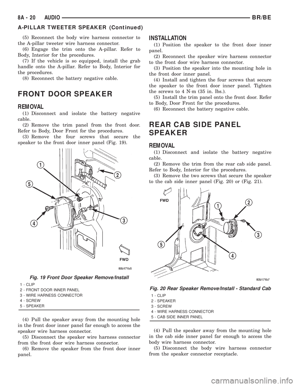
(3) Remove the four screws that secure the
speaker to the front door inner panel (Fig. 19).
(4) Pull the speaker away from the mounting hole
in the front door inner panel far enough to access the
speaker wire harness connector.
(5) Disconnect the speaker wire harness connector
from the front door wire harness connector.
(6) Remove the speaker from the front door inner
panel.
INSTALLATION
(1) Position the speaker to the front door inner
panel.
(2) Reconnect the speaker wire harness connector
to the front door wire harness connector.
(3) Position the speaker into the mounting hole in
the front door inner panel.
(4) Install and tighten the four screws that secure
the speaker to the front door inner panel. Tighten
the screws to 4 N´m (35 in. lbs.).
(5) Install the trim panel onto the front door. Refer
to Body, Door Front for the procedures.
(6) Reconnect the battery negative cable.
REAR CAB SIDE PANEL
SPEAKER
REMOVAL
(1) Disconnect and isolate the battery negative
cable.
(2) Remove the trim from the rear cab side panel.
Refer to Body, Interior for the procedures.
(3) Remove the two screws that secure the speaker
to the cab side inner panel (Fig. 20) or (Fig. 21).
(4) Pull the speaker away from the mounting hole
in the cab side inner panel far enough to access the
body wire harness connector.
(5) Disconnect the body wire harness connector
from the speaker connector receptacle.
Fig. 19 Front Door Speaker Remove/Install
1 - CLIP
2 - FRONT DOOR INNER PANEL
3 - WIRE HARNESS CONNECTOR
4 - SCREW
5 - SPEAKERFig. 20 Rear Speaker Remove/Install - Standard Cab
1 - CLIP
2 - SPEAKER
3 - SCREW
4 - WIRE HARNESS CONNECTOR
5 - CAB SIDE INNER PANEL
8A - 20 AUDIOBR/BE
A-PILLAR TWEETER SPEAKER (Continued)
Page 444 of 2889
(6) Remove the speaker from the cab side inner
panel.
INSTALLATION
(1) Position the speaker to the cab side inner
panel.
(2) Reconnect the body wire harness connector to
the speaker connector receptacle.
(3) Position the speaker into the mounting hole in
the cab side inner panel.
(4) Install and tighten the two screws that secure
the speaker to the cab side inner panel. Tighten the
screws to 4 N´m (35 in. lbs.).
(5) Install the trim onto the rear cab side panel.
Refer to Body, Interior for the procedures.
(6) Reconnect the battery negative cable.
REAR DOOR SPEAKER
REMOVAL
(1) Disconnect and isolate the battery negative
cable.
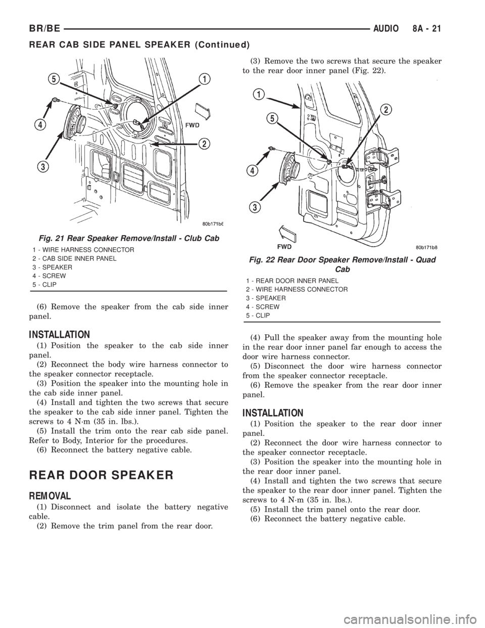
(2) Remove the trim panel from the rear door.(3) Remove the two screws that secure the speaker
to the rear door inner panel (Fig. 22).
(4) Pull the speaker away from the mounting hole
in the rear door inner panel far enough to access the
door wire harness connector.
(5) Disconnect the door wire harness connector
from the speaker connector receptacle.
(6) Remove the speaker from the rear door inner
panel.
INSTALLATION
(1) Position the speaker to the rear door inner
panel.
(2) Reconnect the door wire harness connector to
the speaker connector receptacle.
(3) Position the speaker into the mounting hole in
the rear door inner panel.
(4) Install and tighten the two screws that secure
the speaker to the rear door inner panel. Tighten the
screws to 4 N´m (35 in. lbs.).
(5) Install the trim panel onto the rear door.
(6) Reconnect the battery negative cable.
Fig. 21 Rear Speaker Remove/Install - Club Cab
1 - WIRE HARNESS CONNECTOR
2 - CAB SIDE INNER PANEL
3 - SPEAKER
4 - SCREW
5 - CLIP
Fig. 22 Rear Door Speaker Remove/Install - Quad
Cab
1 - REAR DOOR INNER PANEL
2 - WIRE HARNESS CONNECTOR
3 - SPEAKER
4 - SCREW
5 - CLIP
BR/BEAUDIO 8A - 21
REAR CAB SIDE PANEL SPEAKER (Continued)