2001 DODGE RAM side mirrors
[x] Cancel search: side mirrorsPage 516 of 2889
HEATED SYSTEMS
TABLE OF CONTENTS
page page
HEATED MIRRORS......................... 1 HEATED SEATSYSTEM..................... 5
HEATED MIRRORS
TABLE OF CONTENTS
page page
HEATED MIRRORS
DESCRIPTION............................1
OPERATION.............................2
DIAGNOSIS AND TESTING..................2
HEATED MIRROR SYSTEM................2
MIRROR SWITCH
DESCRIPTION............................3
OPERATION.............................3DIAGNOSIS AND TESTING..................3
HEATED MIRROR SWITCH................3
HEATED MIRROR GRID
DESCRIPTION............................4
OPERATION.............................4
DIAGNOSIS AND TESTING..................0
HEATED MIRROR GRID...................4
HEATED MIRRORS
DESCRIPTION - HEATED MIRROR SYSTEM
Electrically heated outside rear view mirrors are
an additional factory-installed option on models that
are equipped with factory-installed dual power mir-
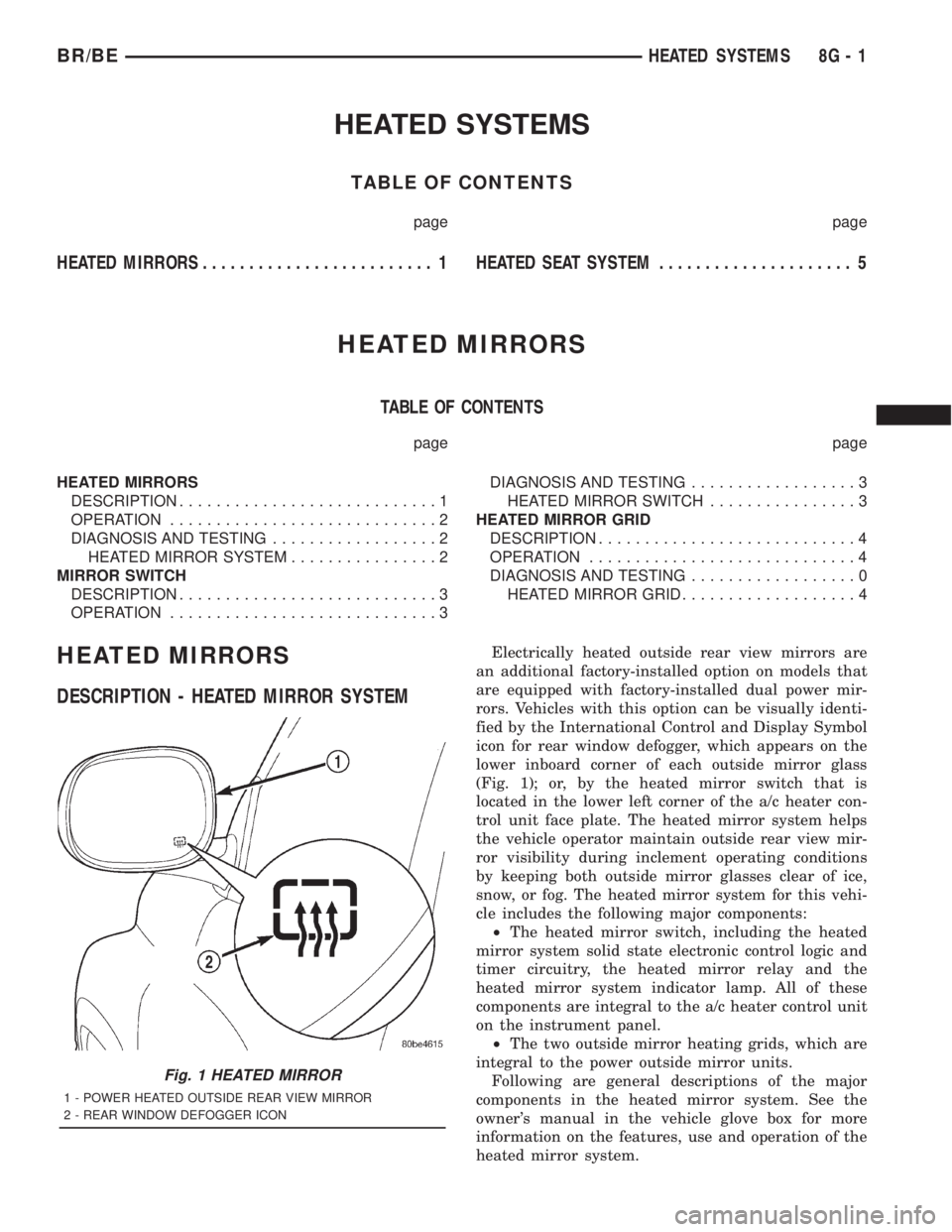
rors. Vehicles with this option can be visually identi-
fied by the International Control and Display Symbol
icon for rear window defogger, which appears on the
lower inboard corner of each outside mirror glass
(Fig. 1); or, by the heated mirror switch that is
located in the lower left corner of the a/c heater con-
trol unit face plate. The heated mirror system helps
the vehicle operator maintain outside rear view mir-
ror visibility during inclement operating conditions
by keeping both outside mirror glasses clear of ice,
snow, or fog. The heated mirror system for this vehi-
cle includes the following major components:
²The heated mirror switch, including the heated
mirror system solid state electronic control logic and
timer circuitry, the heated mirror relay and the
heated mirror system indicator lamp. All of these
components are integral to the a/c heater control unit
on the instrument panel.
²The two outside mirror heating grids, which are
integral to the power outside mirror units.
Following are general descriptions of the major
components in the heated mirror system. See the
owner's manual in the vehicle glove box for more
information on the features, use and operation of the
heated mirror system.
Fig. 1 HEATED MIRROR
1 - POWER HEATED OUTSIDE REAR VIEW MIRROR
2 - REAR WINDOW DEFOGGER ICON
BR/BEHEATED SYSTEMS 8G - 1
Page 517 of 2889
OPERATION - HEATED MIRROR SYSTEM
The solid state electronic control logic and timer
circuitry for the heated mirror system receives bat-
tery current from a fuse in the Junction Block (JB)
only when the ignition switch is in the On or Start
positions. After the heated mirror system is turned
On, the electronic control logic and timer circuitry
will automatically turn the system off after a pro-
grammed time interval of about fifteen minutes.
After the initial time interval has expired, if the
heated mirror switch is depressed and released a sec-
ond time during the same ignition cycle, the elec-
tronic control logic and timer circuitry will
automatically turn the heated mirror system off after
a programmed time interval of about five minutes.
The heated mirror system will be shut off automati-
cally if the ignition switch is turned to the Off or
Accessory positions. After the heated mirror system
is turned On, it can also be turned off manually by
depressing and releasing the heated mirror switch a
second time.
When the heated mirror system is turned On, the
heated mirror system control logic and timer cir-
cuitry energizes the heated mirror system indicator
lamp and the heated mirror relay. When energized,
the heated mirror relay supplies fused ignition
switch output (run/start) current from a fuse in the
JB to the outside mirror heating grids located behind
the mirror glass of each of the outside rear view mir-
rors. When energized, each of the outside mirror
heating grids produces enough heat to warm the
glass of the outside rear view mirrors.
DIAGNOSIS AND TESTING - HEATED MIRROR
SYSTEM
If only one of the outside mirror heating grids is
inoperative, perform continuity checks on the circuits
and heater grid for that mirror only. If both outside
mirror heating grids are inoperative, proceed with
the heated mirror system diagnosis as follows. (Refer
to Appropriate Wiring Information).
WARNING: ON VEHICLES EQUIPPED WITH AIR-
BAGS, DISABLE THE AIRBAG SYSTEM BEFORE
ATTEMPTING ANY STEERING WHEEL, STEERING
COLUMN, OR INSTRUMENT PANEL COMPONENT
DIAGNOSIS OR SERVICE. DISCONNECT AND ISO-
LATE THE BATTERY NEGATIVE (GROUND) CABLE,
THEN WAIT TWO MINUTES FOR THE AIRBAG SYS-
TEM CAPACITOR TO DISCHARGE BEFORE PER-
FORMING FURTHER DIAGNOSIS OR SERVICE. THIS
IS THE ONLY SURE WAY TO DISABLE THE AIRBAG
SYSTEM. FAILURE TO TAKE THE PROPER PRE-
CAUTIONS COULD RESULT IN ACCIDENTAL AIR-
BAG DEPLOYMENT AND POSSIBLE PERSONAL
INJURY.The operation of the heated mirror system can be
confirmed in one of the following manners:
²Turn the ignition switch to the On position.
While monitoring the instrument panel voltmeter,
momentarily depress and release the heated mirror
switch. When the heated mirror system is turned On,
a distinct voltmeter needle deflection should be
noted.
²Turn the ignition switch to the On position.
Momentarily depress and release the heated mirror
switch to turn the heated mirror system On. The
heated mirror operation can be checked by feeling
the outside rear view mirror glass. A distinct differ-
ence in temperature between the unheated and
heated mirror glass can be detected within three to
four minutes of system operation.
The above checks will confirm system operation.
Illumination of the heated mirror system indicator
lamp means that there is electrical current available
at the heated mirror relay, but does not confirm that
the electrical current is reaching the outside mirror
heating grids.
If the heated mirror system does not operate, the
problem should be isolated in the following manner:
(1) Confirm that the ignition switch is in the On
position.
(2) Check the fuses in the Power Distribution Cen-
ter (PDC) and in the Junction Block (JB). The fuses
must be tight in their receptacles and all electrical
connections must be secure.
When the above steps have been completed and
both outside mirror heating grids are still inopera-
tive, one or more of the following is faulty:
²Heated mirror switch, electronic control logic
and timer circuitry, and heated mirror relay.
²Heated mirror wire harness circuits or connec-
tors.
²Outside mirror heating grid (both mirror grids
would have to be faulty).
If turning On the heated mirror system produces a
severe voltmeter deflection or fuse failures, check for
a shorted circuit between the output of the heated
mirror relay and the outside mirror heating grids.
8G - 2 HEATED MIRRORSBR/BE
HEATED MIRRORS (Continued)
Page 518 of 2889
MIRROR SWITCH
DESCRIPTION
The heated mirror switch, the heated mirror sys-
tem indicator lamp, the heated mirror system solid
state electronic control logic and timer circuitry and
the heated mirror relay are all integral to the a/c
heater control, which is located between the instru-
ment cluster and the radio near the center of the
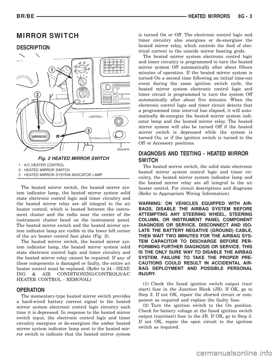
instrument cluster bezel on the instrument panel.
The heated mirror switch and the heated mirror sys-
tem indicator lamp are visible in the lower left corner
of the a/c heater control face plate (Fig. 2).
The heated mirror switch, the heated mirror sys-
tem indicator lamp, the heated mirror system solid
state electronic control logic and timer circuitry and
the heated mirror relay cannot be repaired. If any of
these components is damaged or faulty, the entire a/c
heater control must be replaced. (Refer to 24 - HEAT-
ING & AIR CONDITIONING/CONTROLS/A/C
HEATER CONTROL - REMOVAL)
OPERATION
The momentary-type heated mirror switch provides
a hard-wired battery current signal to the heated
mirror system electronic control logic circuitry each
time it is depressed. In response to the heated mirror
switch input, the electronic control logic and timer
circuitry energizes or de-energizes the amber heated
mirror system indicator lamp next to the heated mir-
ror switch to indicate that the heated mirror systemis turned On or Off. The electronic control logic and
timer circuitry also energizes or de-energizes the
heated mirror relay, which controls the feed of elec-
trical current to the outside mirror heating grids.
The heated mirror system electronic control logic
and timer circuitry is programmed to turn the heated
mirror system Off automatically after about fifteen
minutes of operation. If the heated mirror system is
turned On a second time following an initial time-out
event during the same ignition switch cycle, the
heated mirror system electronic control logic and
timer circuit is programmed to turn the system Off
automatically after about five minutes. When the
electronic control logic and timer circuit detects that
a programmed time interval has elapsed, it will auto-
matically de-energize the heated mirror system indi-
cator lamp and the heated mirror relay. The heated
mirror system will also be turned Off if the heated
mirror switch is depressed while the system is
turned On, or if the ignition switch is turned to the
Off or Accessory positions.
DIAGNOSIS AND TESTING - HEATED MIRROR
SWITCH
The heated mirror switch, the solid state electronic
heated mirror system control logic and timer cir-
cuitry, the heated mirror system indicator lamp and
the heated mirror relay are all integral to the a/c
heater control. For circuit descriptions and diagrams
(Refer to Appropriate Wiring Information).
WARNING: ON VEHICLES EQUIPPED WITH AIR-
BAGS, DISABLE THE AIRBAG SYSTEM BEFORE
ATTEMPTING ANY STEERING WHEEL, STEERING
COLUMN, OR INSTRUMENT PANEL COMPONENT
DIAGNOSIS OR SERVICE. DISCONNECT AND ISO-
LATE THE BATTERY NEGATIVE (GROUND) CABLE,
THEN WAIT TWO MINUTES FOR THE AIRBAG SYS-
TEM CAPACITOR TO DISCHARGE BEFORE PER-
FORMING FURTHER DIAGNOSIS OR SERVICE. THIS
IS THE ONLY SURE WAY TO DISABLE THE AIRBAG
SYSTEM. FAILURE TO TAKE THE PROPER PRE-
CAUTIONS COULD RESULT IN ACCIDENTAL AIR-
BAG DEPLOYMENT AND POSSIBLE PERSONAL
INJURY.
(1) Check the fused ignition switch output (run/
start) fuse in the Junction Block (JB). If OK, go to
Step 2. If not OK, repair the shorted circuit or com-
ponent as required and replace the faulty fuse.
(2) Turn the ignition switch to the On position.
Check for battery voltage at the fused ignition switch
output (run/start) fuse in the JB. If OK, go to Step 3.
If not OK, repair the open circuit to the ignition
switch as required.
Fig. 2 HEATED MIRROR SWITCH
1 - A/C HEATER CONTROL
2 - HEATED MIRROR SWITCH
3 - HEATED MIRROR SYSTEM INDICATOR LAMP
BR/BEHEATED MIRRORS 8G - 3
Page 519 of 2889
(3) Disconnect and isolate the battery negative
cable. Disconnect the 3-way instrument panel wire
harness connector for the heated mirror switch from
the heated mirror switch connector receptacle on the
back of the a/c heater control. Check for continuity
between the ground circuit cavity of the wire harness
connector and a good ground. There should be conti-
nuity. If OK, go to Step 4. If not OK, repair the open
ground circuit to ground as required.
(4) Reconnect the battery negative cable. Turn the
ignition switch to the On position. Check for battery
voltage at the fused ignition switch output (run/start)
circuit cavity of the 3-way instrument panel wire
harness connector for the heated mirror switch. If
OK, go to Step 5. If not OK, repair the open fused
ignition switch output (run/start) circuit to the fuse
in the JB as required.
(5) Turn the ignition switch to the Off position.
Disconnect and isolate the battery negative cable.
Reconnect the 3-way instrument panel wire harness
connector for the heated mirror switch to the heated
mirror switch connector receptacle on the back of the
a/c heater control. Reconnect the battery negative
cable. Turn the ignition switch to the On position.
Depress and release the heated mirror switch. The
amber heated mirror system indicator lamp next to
the heated mirror switch button should light. If OK,
go to Step 6. If not OK, replace the faulty a/c heater
control.
(6) Back probe the fused heated mirror relay out-
put circuit cavity of the 3-way instrument panel wire
harness connector for the heated mirror switch on
the back of the a/c heater control and check for volt-
age (battery voltage less the resistance in both out-
side mirror heating grids). If OK, (Refer to 8 -
ELECTRICAL/HEATED MIRRORS/HEATED MIR-
ROR GRID - DIAGNOSIS AND TESTING).
HEATED MIRROR GRID
DESCRIPTION
Vehicles equipped with the optional heated mirror
system have an electrically operated heating grid
located behind the mirror glass of each power oper-
ated outside rear view mirror. The outside mirror
heating grid consists of two thin laminations of plas-
tic that approximate the outer dimensions and shape
of the mirror glass. A single length of resistor wire
weaves in a back and forth pattern between, and is
held in place by the two thin laminations of plastic.
The two ends of the resistor wire terminate near the
inboard edge of the grid, where they are soldered to
the ground feed and battery current feed wires con-
tained in the power mirror wire harness. The heating
grid is then sandwiched between the back of themolded plastic mirror glass case and the mirror
glass, where it remains in direct contact with the
back of the mirror glass at all times.
The outside mirror heating grids cannot be
repaired and, if faulty or damaged, the entire outside
power mirror unit must be replaced. Refer to Power
Mirrors for the service procedures.
OPERATION
One end of the outside mirror heating grid resistor
wire is connected to a ground feed at all times
through a body ground screw located inside the left
rear corner of the truck cab. Battery current is
directed to the other end of the outside mirror heat-
ing grid resistor wire by the energized heated mirror
relay when the heated mirror switch is in the On
position. As electrical current passes through the
heating grid, the resistance of the wire in the heating
grid converts some of that electrical current into
heat. The heat produced by the heating grid is then
conducted through the back of the mirror glass to
help keep the glass clear of ice, snow or fog.
DIAGNOSIS AND TESTING - HEATED MIRROR
GRID
For circuit descriptions and diagrams (Refer to
Appropriate Wiring Information).
(1) Disconnect and isolate the battery negative
cable. Disconnect the door wire harness connector
from the power mirror wire harness connector at the
power mirror with the inoperative heating grid.
Check for continuity between the ground circuit cav-
ity in the door wire harness connector for the power
mirror and a good ground. If OK, go to Step 2. If not
OK, repair the open ground circuit to ground as
required.
(2) Reconnect the battery negative cable. Turn the
ignition switch to the On position. Turn on the
heated mirror system. Check for voltage (battery
voltage less the resistance in the outside mirror heat-
ing grid that is still connected) at the fused heated
mirror relay output circuit cavity in the door wire
harness connector for the power mirror. If OK, go to
Step 3. If not OK, repair the open fused heated mir-
ror relay output circuit to the heater and air condi-
tioner control unit as required.
(3) Check the outside mirror heating grid by test-
ing for continuity between the ground circuit and the
fused heated mirror relay output circuit cavities in
the power mirror wire harness connector. There
should be continuity. If not OK, replace the faulty
power mirror. If OK, check the resistance through
the outside mirror heating grid. The correct resis-
tance should be from 10 to 16 ohms when measured
at an ambient temperature of 21É C (70É F). If not
OK, replace the faulty power mirror.
8G - 4 HEATED MIRRORSBR/BE
MIRROR SWITCH (Continued)
Page 659 of 2889

POWER MIRRORS
TABLE OF CONTENTS
page page
POWER MIRRORS
DESCRIPTION...........................10
OPERATION.............................10
AUTOMATIC DAY / NIGHT MIRROR
DESCRIPTION...........................10
OPERATION.............................11
DIAGNOSIS AND TESTING.................11
AUTOMATIC DAY/NIGHT MIRROR..........11
REMOVAL..............................12
INSTALLATION...........................12
POWER MIRROR SWITCH
DESCRIPTION...........................12OPERATION.............................12
REMOVAL..............................12
INSTALLATION...........................13
SIDEVIEW MIRROR
DESCRIPTION...........................13
OPERATION.............................13
DIAGNOSIS AND TESTING.................13
SIDEVIEW MIRROR.....................13
REMOVAL..............................14
POWER MIRRORS
DESCRIPTION
AUTOMATIC DAY / NIGHT MIRROR
The automatic day/night mirror system is able to
automatically change the reflectance of the inside
rear view mirror in order to reduce the glare of head-
lamps approaching the vehicle from the rear. The
automatic day/night rear view mirror receives bat-
tery current through a fuse in the junction block only
when the ignition switch is in the On position.
OUTSIDE REAR VIEW MIRROR
The heated mirror option includes an electric heat-
ing grid behind the mirror glass in each outside mir-
ror, which can clear the mirror glass of ice, snow, or
fog. The heating grid receives fused battery current
through the heated mirror relay in the heater and air
conditioner control only when the ignition switch is
in the On position, and the heated mirror system is
turned on. (Refer to 8 - ELECTRICAL/HEATED
MIRRORS - DESCRIPTION) for more information.
Refer to the owner's manual in the vehicle glove
box for more information on the features, use and
operation of the power mirror system.
OPERATION
AUTOMATIC DAY / NIGHT MIRROR
A switch located on the bottom of the automatic
day/night mirror housing allows the vehicle operator
to select whether the automatic dimming feature is
operational. When the automatic day/night mirror isturned on, the mirror switch is lighted by an integral
Light-Emitting Diode (LED). The mirror will auto-
matically disable its self-dimming feature whenever
the vehicle is being driven in reverse.
Refer to the owner's manual in the vehicle glove
box for more information on the features, use and
operation of the automatic day/night mirror system.
OUTSIDE REAR VIEW MIRROR
The heated mirror option includes an electric heat-
ing grid behind the mirror glass in each outside mir-
ror, which can clear the mirror glass of ice, snow, or
fog. The heating grid receives fused battery current
through the heated mirror relay in the heater and air
conditioner control only when the ignition switch is
in the On position, and the heated mirror system is
turned on. (Refer to 8 - ELECTRICAL/HEATED
MIRRORS - OPERATION) for more information.
Refer to the owner's manual in the vehicle glove
box for more information on the features, use and
operation of the power mirror system.
AUTOMATIC DAY / NIGHT
MIRROR
DESCRIPTION
The automatic day/night mirror uses a thin layer
of electrochromic material between two pieces of con-
ductive glass to make up the face of the mirror.
When the mirror switch is in the On position, two
photocell sensors are used by the mirror circuitry to
monitor external light levels and adjust the reflec-
tance of the mirror.
8N - 10 POWER MIRRORSBR/BE
Page 660 of 2889

OPERATION
The ambient photocell sensor is located on the for-
ward-facing (windshield side) of the rear view mirror
housing, and detects the ambient light levels outside
of the vehicle. The headlamp photocell sensor is
located inside the rear view mirror housing behind
the mirror glass and faces rearward, to detect the
level of the light being received at the rear window
side of the mirror. When the circuitry of the auto-
matic day/night mirror detects that the difference
between the two light levels is too great (the light
level received at the rear of the mirror is much
higher than that at the front of the mirror), it begins
to darken the mirror.
The automatic day/night mirror circuitry also mon-
itors the transmission using an input from the
backup lamp circuit. The mirror circuitry is pro-
grammed to automatically disable its self-dimming
feature whenever it senses that the transmission
backup lamp circuit is energized.
The automatic day/night mirror is a completely
self-contained unit and cannot be repaired. If faulty
or damaged, the entire mirror assembly must be
replaced.
DIAGNOSIS AND TESTING - AUTOMATIC
DAY/NIGHT MIRROR
For circuit descriptions and diagrams, refer to the
appropriate wiring information. The wiring informa-
tion includes wiring diagrams, proper wire and con-
nector repair procedures, details of wire harness
routing and retention, connector pin-out information
and location views for the various wire harness con-
nectors, splices and grounds.
(1) Check the fuse in the junction block. If OK, go
to Step 2. If not OK, repair the shorted circuit or
component as required replace the faulty fuse.
(2) Turn the ignition switch to the On position.
Check for battery voltage at the fuse in the junction
block. If OK, go to Step 3. If not OK, repair the open
circuit to the ignition switch as required.
(3) Turn the ignition switch to the Off position.
Disconnect and isolate the battery negative cable.
Unplug the wire harness connector from the auto-
matic day/night mirror (Fig. 1). Connect the battery
negative cable. Turn the ignition switch to the On
position. Check for battery voltage at the fused igni-
tion switch output (run/start) circuit cavity of the
automatic day/night mirror wire harness connector. If
OK, go to Step 4. If not OK, repair the open circuit to
the junction block as required.
(4) Turn the ignition switch to the Off position.
Disconnect and isolate the battery negative cable.
Check for continuity between the ground circuit cav-
ity of the automatic day/night mirror wire harness
connector and a good ground. There should be conti-nuity. If OK, go to Step 5. If not OK, repair the cir-
cuit to ground as required.
(5) Connect the battery negative cable. Turn the
ignition switch to the On position. Set the parking
brake. Place the transmission gear selector lever in
the Reverse position. Check for battery voltage at the
backup lamp switch output circuit cavity of the auto-
matic day/night mirror wire harness connector. If
OK, go to Step 6. If not OK, repair the open circuit
as required.
(6) Turn the ignition switch to the Off position.
Disconnect the battery negative cable. Plug in the
automatic day/night mirror wire harness connector.
Connect the battery negative cable. Turn the ignition
switch to the On position. Place the transmission
gear selector lever in the Neutral position. Place the
mirror switch in the On (LED in the mirror switch is
lighted) position. Cover the forward facing ambient
photocell sensor to keep out any ambient light.
NOTE: The ambient photocell sensor must be cov-
ered completely, so that no light reaches the sen-
sor. Use a finger pressed tightly against the sensor,
or cover the sensor completely with electrical tape.
(7) Shine a light into the rearward facing head-
lamp photocell sensor. The mirror glass should
darken. If OK, go to Step 8. If not OK, replace the
faulty automatic day/night mirror unit.
(8) With the mirror glass darkened, place the
transmission gear selector lever in the Reverse posi-
tion. The mirror should return to its normal reflec-
tance. If not OK, replace the faulty automatic day/
night mirror unit.
Fig. 1 Automatic Day/Night Mirror
BR/BEPOWER MIRRORS 8N - 11
AUTOMATIC DAY / NIGHT MIRROR (Continued)
Page 661 of 2889
REMOVAL
(1) Disconnect and isolate the battery negative
cable.
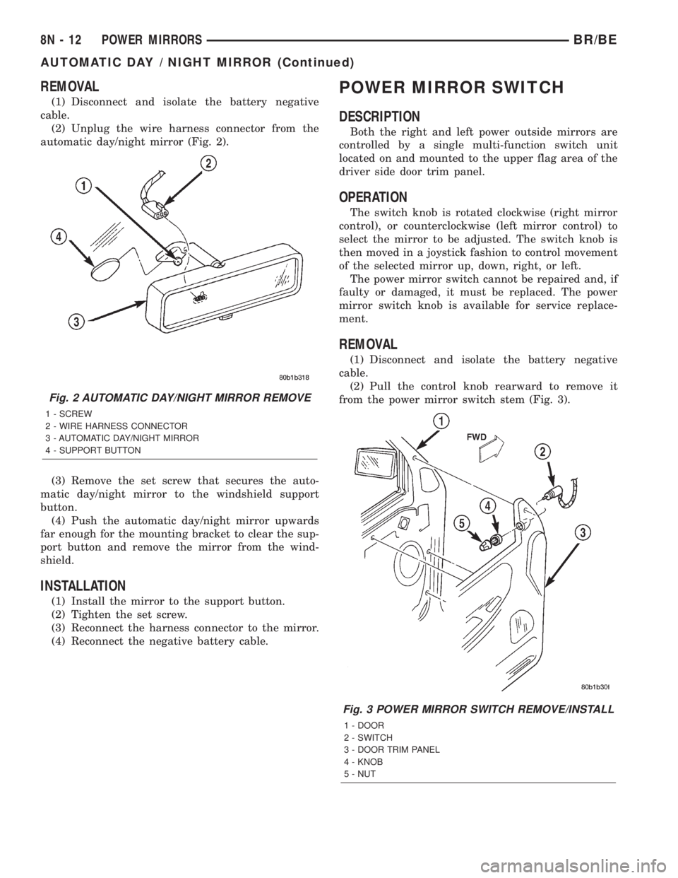
(2) Unplug the wire harness connector from the
automatic day/night mirror (Fig. 2).
(3) Remove the set screw that secures the auto-
matic day/night mirror to the windshield support
button.
(4) Push the automatic day/night mirror upwards
far enough for the mounting bracket to clear the sup-
port button and remove the mirror from the wind-
shield.
INSTALLATION
(1) Install the mirror to the support button.
(2) Tighten the set screw.
(3) Reconnect the harness connector to the mirror.
(4) Reconnect the negative battery cable.
POWER MIRROR SWITCH
DESCRIPTION
Both the right and left power outside mirrors are
controlled by a single multi-function switch unit
located on and mounted to the upper flag area of the
driver side door trim panel.
OPERATION
The switch knob is rotated clockwise (right mirror
control), or counterclockwise (left mirror control) to
select the mirror to be adjusted. The switch knob is
then moved in a joystick fashion to control movement
of the selected mirror up, down, right, or left.
The power mirror switch cannot be repaired and, if
faulty or damaged, it must be replaced. The power
mirror switch knob is available for service replace-
ment.
REMOVAL
(1) Disconnect and isolate the battery negative
cable.
(2) Pull the control knob rearward to remove it
from the power mirror switch stem (Fig. 3).
Fig. 2 AUTOMATIC DAY/NIGHT MIRROR REMOVE
1 - SCREW
2 - WIRE HARNESS CONNECTOR
3 - AUTOMATIC DAY/NIGHT MIRROR
4 - SUPPORT BUTTON
Fig. 3 POWER MIRROR SWITCH REMOVE/INSTALL
1 - DOOR
2 - SWITCH
3 - DOOR TRIM PANEL
4 - KNOB
5 - NUT
8N - 12 POWER MIRRORSBR/BE
AUTOMATIC DAY / NIGHT MIRROR (Continued)
Page 662 of 2889
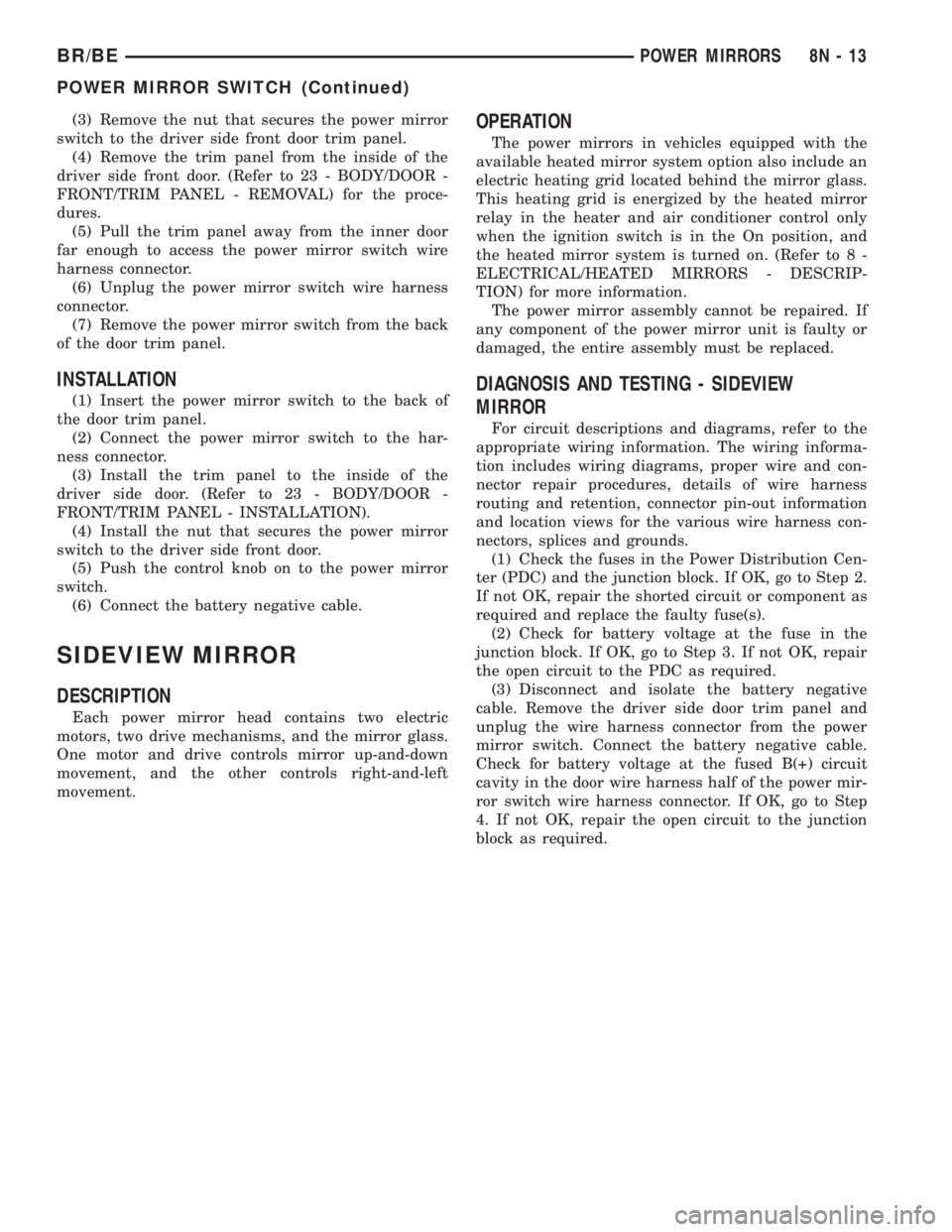
(3) Remove the nut that secures the power mirror
switch to the driver side front door trim panel.
(4) Remove the trim panel from the inside of the
driver side front door. (Refer to 23 - BODY/DOOR -
FRONT/TRIM PANEL - REMOVAL) for the proce-
dures.
(5) Pull the trim panel away from the inner door
far enough to access the power mirror switch wire
harness connector.
(6) Unplug the power mirror switch wire harness
connector.
(7) Remove the power mirror switch from the back
of the door trim panel.
INSTALLATION
(1) Insert the power mirror switch to the back of
the door trim panel.
(2) Connect the power mirror switch to the har-
ness connector.
(3) Install the trim panel to the inside of the
driver side door. (Refer to 23 - BODY/DOOR -
FRONT/TRIM PANEL - INSTALLATION).
(4) Install the nut that secures the power mirror
switch to the driver side front door.
(5) Push the control knob on to the power mirror
switch.
(6) Connect the battery negative cable.
SIDEVIEW MIRROR
DESCRIPTION
Each power mirror head contains two electric
motors, two drive mechanisms, and the mirror glass.
One motor and drive controls mirror up-and-down
movement, and the other controls right-and-left
movement.
OPERATION
The power mirrors in vehicles equipped with the
available heated mirror system option also include an
electric heating grid located behind the mirror glass.
This heating grid is energized by the heated mirror
relay in the heater and air conditioner control only
when the ignition switch is in the On position, and
the heated mirror system is turned on. (Refer to 8 -
ELECTRICAL/HEATED MIRRORS - DESCRIP-
TION) for more information.
The power mirror assembly cannot be repaired. If
any component of the power mirror unit is faulty or
damaged, the entire assembly must be replaced.
DIAGNOSIS AND TESTING - SIDEVIEW
MIRROR
For circuit descriptions and diagrams, refer to the
appropriate wiring information. The wiring informa-
tion includes wiring diagrams, proper wire and con-
nector repair procedures, details of wire harness
routing and retention, connector pin-out information
and location views for the various wire harness con-
nectors, splices and grounds.
(1) Check the fuses in the Power Distribution Cen-
ter (PDC) and the junction block. If OK, go to Step 2.
If not OK, repair the shorted circuit or component as
required and replace the faulty fuse(s).
(2) Check for battery voltage at the fuse in the
junction block. If OK, go to Step 3. If not OK, repair
the open circuit to the PDC as required.
(3) Disconnect and isolate the battery negative
cable. Remove the driver side door trim panel and
unplug the wire harness connector from the power
mirror switch. Connect the battery negative cable.
Check for battery voltage at the fused B(+) circuit
cavity in the door wire harness half of the power mir-
ror switch wire harness connector. If OK, go to Step
4. If not OK, repair the open circuit to the junction
block as required.
BR/BEPOWER MIRRORS 8N - 13
POWER MIRROR SWITCH (Continued)